DE6210 - Dovetail template DEWALT - Free user manual and instructions
Find the device manual for free DE6210 DEWALT in PDF.

| Product Type | Dovetail Jig |
| Brand | DeWALT |
| Model | DE6210 |
| Dovetail Spacing | 25.4 mm (1") |
| Max Workpiece Width | 305 mm |
| Workpiece Thickness | 6 - 30 mm |
| Router Bit Shank Diameter | 8 mm |
| Weight | 9 kg |
| Power Source | Not applicable (router accessory) |
| Main Functions | Creating dovetail joints (through, half-blind, sliding) and box joints |
| Joint Types Possible | Through dovetail, half-blind, rabbeted half-blind, sliding dovetail; box joints |
| Templates Included | Template for through and sliding dovetails; template for half-blind dovetails and box joints (DE6212) |
| Router Bit Included | Type A dovetail bit (13.5 mm, 7° angle) |
| Guide Bushings Included | Type A bushing (19 mm) with lock nut |
| Adapter Plates Included | For DW613/DW614/DW615, DW620/DW621/DW626, DW624/DW625E/DW629 |
| Compatible Materials | Natural and handworked woods |
| Safety | Wear safety glasses, snug-fitting clothing, dust mask; keep work area clean |
| Maintenance | No lubrication needed; clean regularly; repairs by an authorized DeWALT service center |
| Warranty | 1 year warranty on manufacturing defects; 30 day satisfaction guarantee |
| Optional Accessories | Bushing set DE6952, DE6274, DE6260; additional router bits |
Frequently Asked Questions - DE6210 DEWALT
User questions about DE6210 DEWALT
0 question about this device. Answer the ones you know or ask your own.
Ask a new question about this device
Download the instructions for your Dovetail template in PDF format for free! Find your manual DE6210 - DEWALT and take your electronic device back in hand. On this page are published all the documents necessary for the use of your device. DE6210 by DEWALT.
USER MANUAL DE6210 DEWALT
A1
A2
A3
B
natural_image
Technical illustration of a mechanical assembly with no visible text or symbolsC
D1
D2
E1
E2
E3
F1
natural_image
Simple 3D diagram of a rectangular shelf mounted on a vertical support (no text or symbols)F2
G1

G2
G3
H1
H2
H3

K1
K2
natural_image
Technical line drawing of a mechanical conveyor system with rollers and conveyor belts (no text or symbols)K3
SINKNINGSANORDNING DE6210/DE6212/DE6215
Tillykke!
You have chosen a D ∈ WALT product. Years of experience, thorough product development and innovation make D ∈ WALT one of the most reliable partners for professional users.
Technical data
| 5126ED 2126ED 0126ED | ||||
| Dovetail spacing | mm | 25.4 | 25.4 | 12.7 |
| Max. workpiece width | mm | 305 | 305 | 305 |
| Workpiece thickness | mm | 6 - 30 | 6 - 30 | 6 - 30 |
| Cutter shank diameter | mm | 6.35 | 6.35 | 6.35 |
| Weight | kg | 9 | 9 | 1 |
The following symbols are used throughout this manual:

Denotes risk of personal injury, loss of life or damage to the tool in case of non-observance of the instructions in this manual.
Manufacturer's declaration

DEWALT declares that this unit has been designed in compliance with 98/37/EC.
This unit must not be put into service until it was established that the Power Tool to be connected to this unit is in compliance with 98/37/EC (identified by the CE-marking on the Power Tool).
Director Engineering and Product Development Horst Großmann

Observe the safety regulations in the instruction manual of the Power Tool to be connected to this attachment. Also observe any applicable additional safety rules. Read the following safety instructions before attempting to operate this product.
Keep these instructions in a safe place!
General
1 Keep work area clean
Cluttered areas and benches can cause accidents.
2 Keep children away
Do not let children come into contact with the tool or its attachments. Keep all people away from the work area.
3 Dress properly
Do not wear loose clothing or jewellery. They can be caught in moving parts. Preferably wear rubber gloves and non-slip footwear when working outdoors. Wear protective hair covering to keep long hair out of the way.
4 Wear safety goggles
Also use a face or dust mask in case the operations produce dust or fl ying particles.
5 Beware of maximum sound pressure
Take appropriate measures for the protection of hearing if the sound pressure of 85dB(A) is exceeded.
6 Stay alert
Watch what you are doing. Use common sense. Do not operate the tool when you are tired.
7 Use appropriate tool
The intended use is laid down in this instruction manual. Do not force small tools or attachments to do the job of a heavy-duty tool. The tool will do the job better and safer at the rate for which it was intended.
Warning! The use of any accessory or attachment or performance of any operation with this tool, other than those recommended in this instruction manual may present a risk of personal injury.
8 Have your Power Tool Attachment repaired by an authorized DE WALT repair agent
Repair of your Power Tool Attachment being a matter of precision and skill, always take it to your D E WALT Authorized Repair Agent.
DE6210/DE6212 - Package contents
The package contains:
1 Dovetailing attachment
1 Dovetailing template (Half-blind and sliding dovetails)
1 Dovetailing template (Through dovetails and box joints) (DE6212)
1 Dovetail cutter type A (13.5 mm (17/32")); cutting angle 7°)
1 Straight cutter type B (10.4 mm (13/32")) (DE6212)
1 Guide bush and lock nut type A (19 mm (3/4"))
1 Guide bush and lock nut type B (15.9 mm (5/8")) (DE6212)
1 Guide bush adaptor plate for DW613/DW614/DW615
1 Guide bush adaptor plate for DW620/DW621/DW626
1 Guide bush adaptor plate for DW624/DW625E/DW629
1 T-handle Allen key
1 Instruction manual
• Take the time to thoroughly read and understand this manual prior to operation.
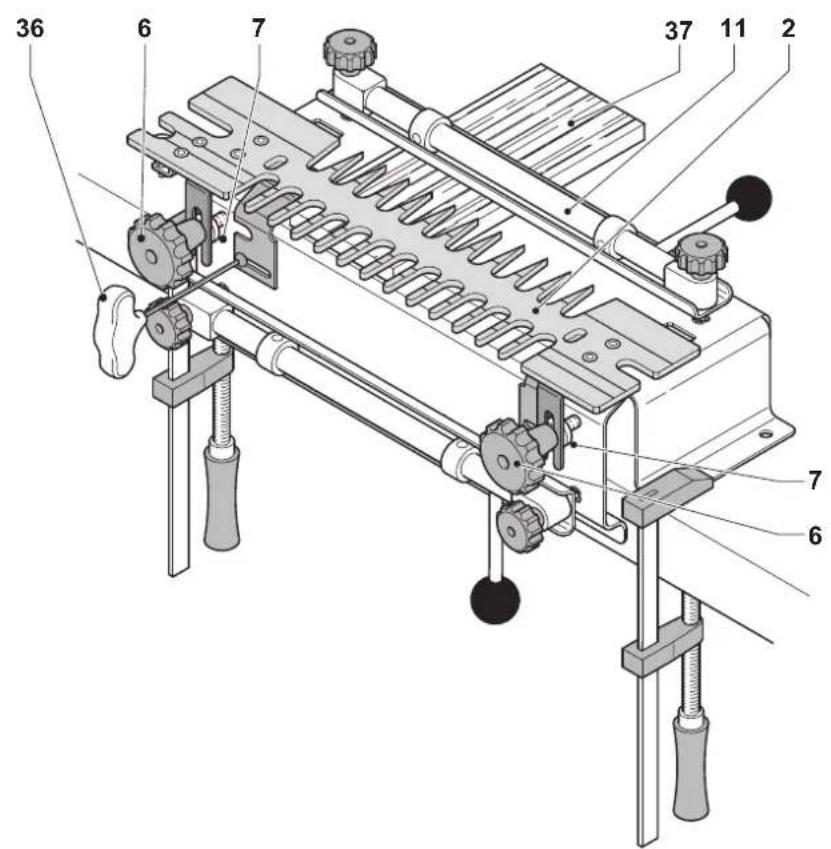
Description (fig. A1 & A2)
The dovetailing attachment DE6210/DE6212/DE6215 allows you to make professional dovetail joints using your router.
Fig. A1
1 Base
2 Dovetailing template
3 Locking lever for front vice
4 Front vice
5 Adjustment knobs for front vice
6 Template position securing knobs
7 Template position adjustment knobs
8 Depth guide
9 Offset guides
10 Adjustment knobs for top vice
11 Top vice
12 Locking lever for top vice
13 Mounting holes
14 Template fingers
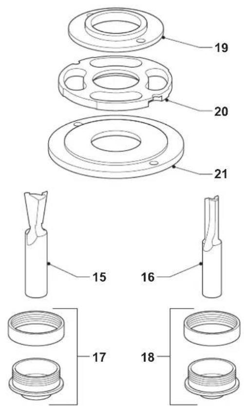
Supplied accessories (fi g. A2)
The following accessories are supplied with the attachment:
15 Dovetail cutter type A
16 Straight cutter type B (DE6212)
17 Guide bush and lock nut type A
18 Guide bush and lock nut type B (DE6212)
19 Guide bush adaptor plate for DW613/DW614/DW615
20 Guide bush adaptor plate for DW620/DW621/DW626
21 Guide bush adaptor plate for DW624/DW625E/DW629
Optional accessories
The cutters supplied with the attachment have to be fitted in an 8 mm collet assembly. The following collet assemblies are available:
- DE6951 collet assembly (for DW613/DW614/DW615/DW620/DW621)
- DE6273 collet assembly (for DW624/DW625E/DW629)
- DE6261 collet assembly (for DW626)
Consult your dealer for further information on the appropriate accessories.
Assembly and adjustment

o refer to your router manual.
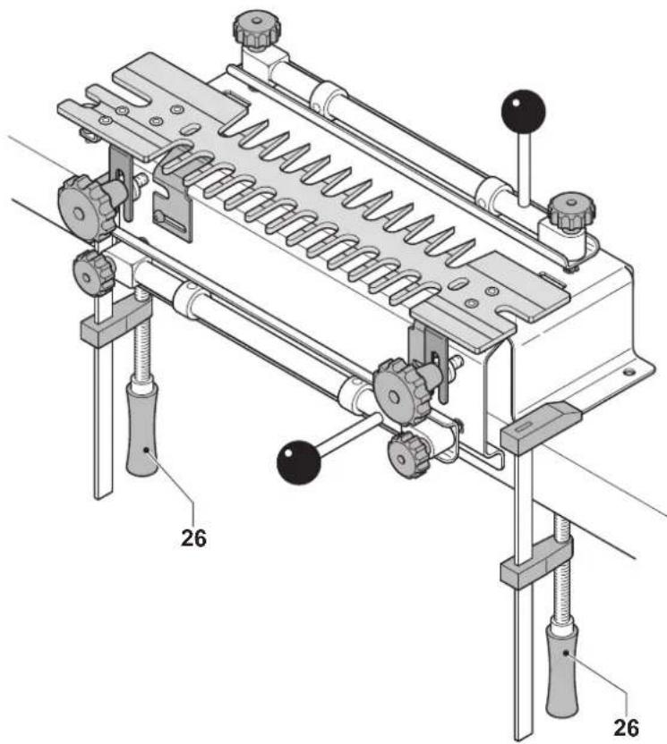
Preparing the dovetailing attachment (fi g. A & B)
- Mount the dovetailing attachment to a workbench with screws of a suitable size. For this purpose, the base has mounting holes (13).
Make sure that the front edge of the base of the attachment projects beyond the workbench.
- Alternatively, mount the dovetailing attachment temporarily on a workbench. Use clamps (26) to mount the dovetailing attachment to the workbench as shown in fig. B.

Always secure the attachment to a stable surface.
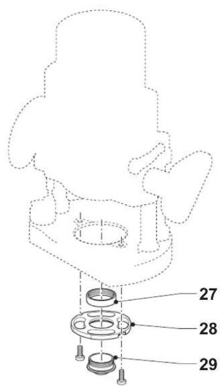
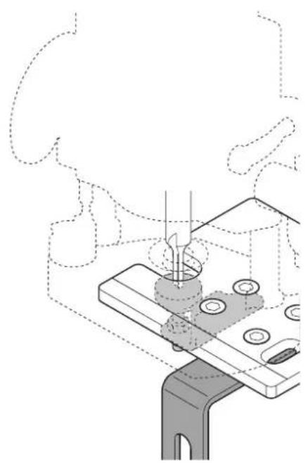
Preparing the router (fi g. C)
In order to accommodate your DE WALT router for use with the attachment, a guide bush adaptor plate assembly has to be fitted to the router base. Other brands of routers may require a separate sub-base to be used.

We recommend to use a router with integrated fi ne adjuster for the depth of cut, or to fi t your router with a suitable fi ne adjuster.
• Fit the adaptor plate (27) to the router base.
- Insert the guide bush (28) into the adaptor plate as shown.
- Secure the guide bush to the adaptor plate using the lock nut (29).
- Insert the required cutter into the collet.
- Adjust the cutter as described below.

Always use the guide bushes supplied with the attachment to guide the router against the template fingers. To select the proper guide bush for a given joint, place the guide bush in the depth setting slot on the left side of the corresponding template. The guide should have a snug fit in the slot.
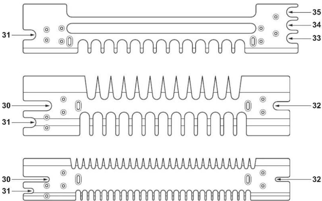
Adjusting the cutter depth (fi g. D1 & D2)
The depth guides on the templates are factory pre-set for the standard joints, but can be adjusted as necessary.
- Lower the cutter just past the edge of the guide bush.
- Slide the router with the guide bush into the depth setting slot that corresponds with the joint to be routed. This is always the slot to the left of the template fi ngers being used.
30 TAILS/BOX for dovetails and box joints
31 HALF-BLIND for half-blind dovetails
32 PINS for dovetail pins
33 1/2" DADO for sliding dovetails (12.7 mm, fi xed)
34 3/8" DADO for sliding dovetails (9.5 mm, fi xed)
35 1/4" DADO for sliding dovetails (6.35 mm, fi xed)
- Lower the router carriage until the cutter contacts the depth guide (8). Lock the router carriage in this position.
Marking and clamping the workpieces (fi g. E - G)
Your dovetailing attachment is capable of making a number of joints including:
- Through dovetails (fi g. E1)
- Half-blind dovetails (fi g. E2)
- Rebated half-blind dovetails (fi g. F1)
-
Sliding dovetails (fi g. F2)
-
Carefully mark the mating parts of the project as shown in fig. E - F.
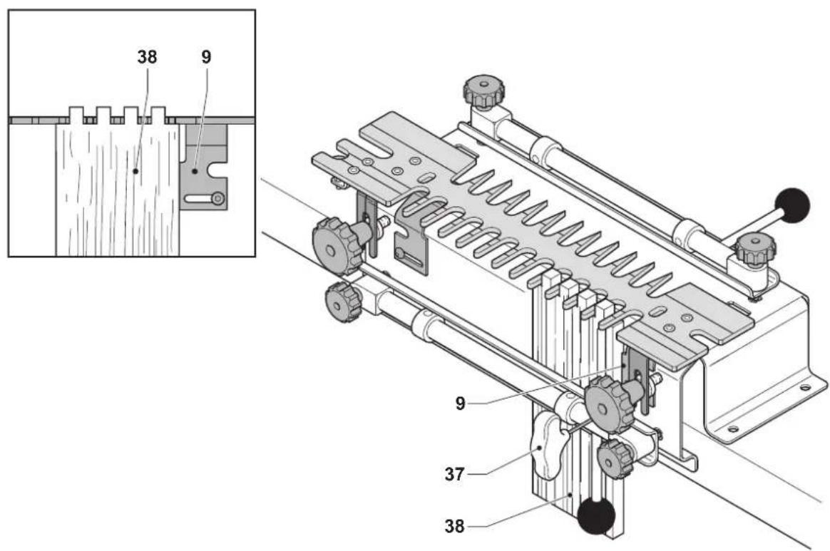
- Loosen the left offset guide (9) using the T-handle Allen key (36). Slide the guide to the far left position.
- Position the horizontal workpiece (37) and clamp it into place using the top vice (11) (fi g. G1). Make sure that the edge of the workpiece does not project beyond the edge of the attachment.
- Insert the lugs of the template (2) between the adjustment knobs (7) and securing knobs (6). Hold the template down with one hand while tightening the securing knobs with the other.
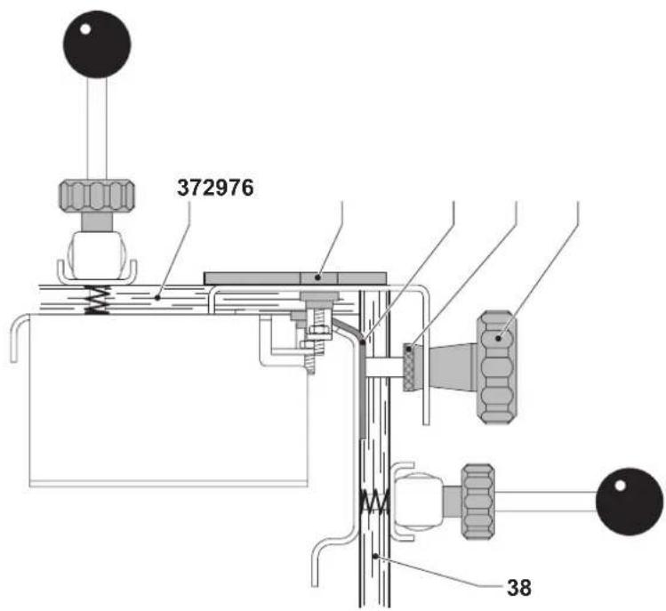
- Position the vertical workpiece (38) centred between the farthest fi nger on the left and the nearest fi nger on the right of the template (fi g. G2). Make sure that the edge of the workpiece is fl ush with the bottom of the template. Clamp the workpiece into place using the front vice (4).
- Slide the left offset guide (9) to the right until it is flush against the vertical workpiece. Fasten the offset guide using the T-handle Allen key (36).
- Loosen the top vice. Move the horizontal workpiece (37) until it is fl ush against the vertical workpiece (38) and the left offset guide (9) (fi g. G3). Tighten the top vice.

- Fit a piece of scrap material (39) of the same thickness as the workpiece to keep the vice even and the templates fl at (fi g. G3).
- Clamp a piece of scrap material tightly against the workpiece to minimise break-out from the cutter.
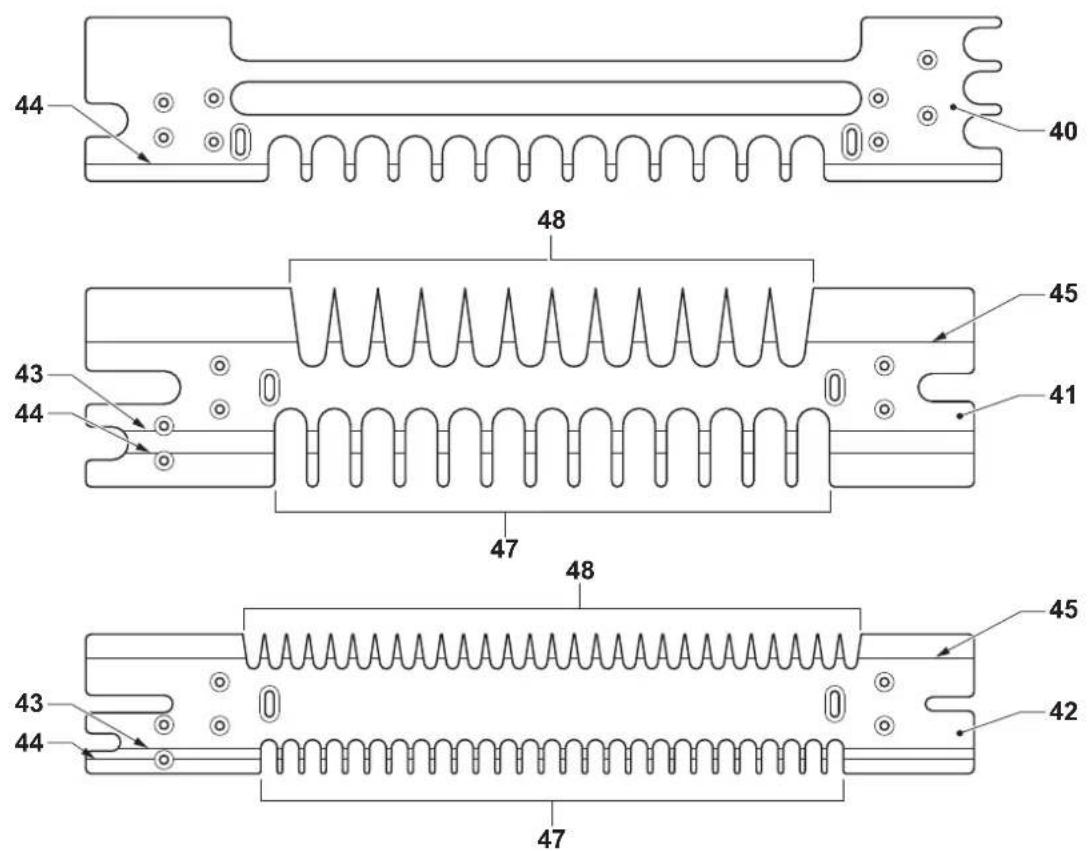
Mounting and adjusting the template (fi g. H1 - H3)
The templates can be used on both sides to enable routing of different joints (fi g. H1).
40 for half-blind and sliding dovetails
41 for through dovetails and box joints (DE6212)
42 for miniature through dovetails and box joints (DE6215)
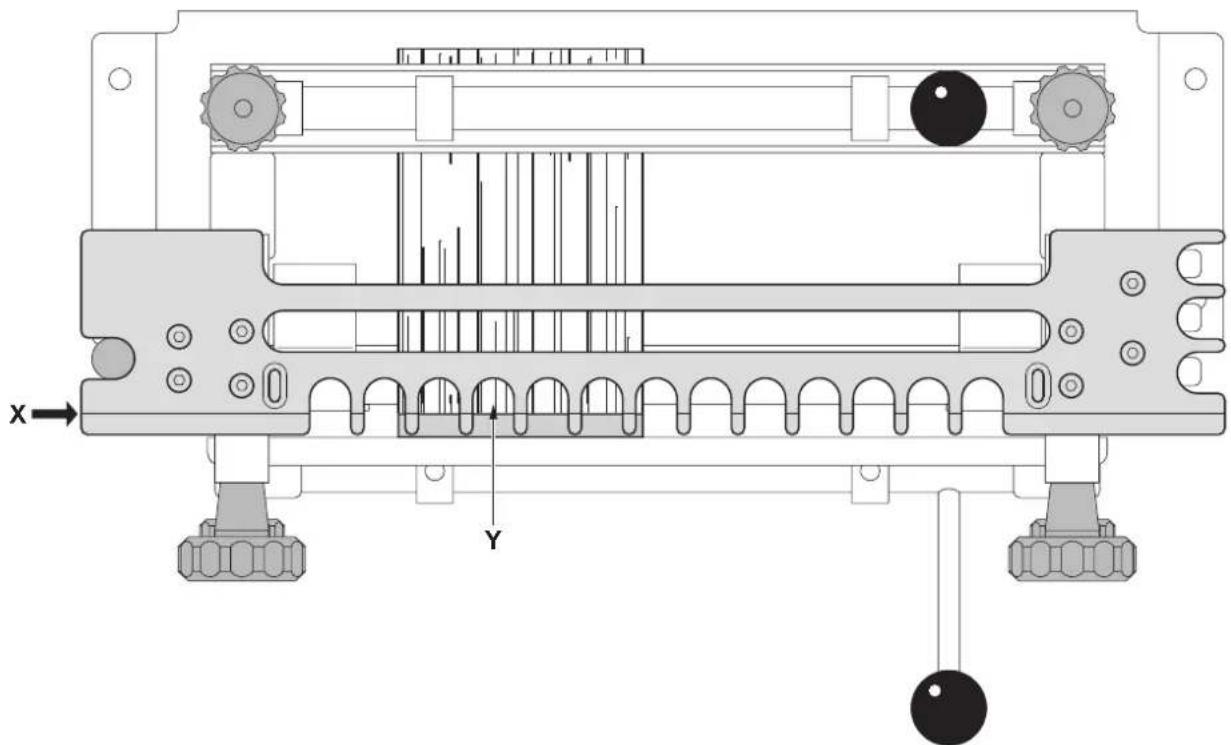
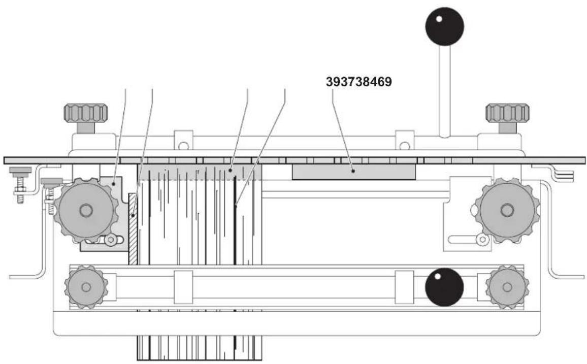
Icons and text on the template indicate the side of the template and the alignment line that have to be used for each joint.
43 TAILS/BOX for through dovetail pins and box joints
44 HALF-BLIND for half-blind dovetails
45 PINS for through dovetail pins
- Insert the lugs of the template (2) between the adjustment knobs (7) and securing knobs (6) (fi g. H2).
- To align the workpieces with the template, lean over the workpiece and look straight down at the alignment line (fi g. H3).
- Rotate the adjustment knobs (6) to align the alignment line X with the joint Y of the two workpieces.
- Secure the template in the correct position by tightening the securing knobs (7).
Instructions for use

Always observe the safety instructions and applicable regulations.

Also refer to your router manual.
Selecting materials
The primary materials for dovetailing are natural and man-made woods. A good-quality hardwood will give an excellent result and minimise splintering.
Properly preparing the materials for your workpiece is the key to good-looking and tight-fi tting results. For the best results, workpieces must be cut at perfect right angles. Workpieces must be fl at and not warped.
Orient the wood so that end grain is joined to end grain to obtain a strong joint.
Optimum material widths
The templates allow making joints up to 305 mm in width. However, some widths will produce a more attractive joint than others as they will include a whole number of dovetails across the material width. The optimal material widths are multiples of 25.4 mm (1") plus 6.35 mm (1/4") (e.g. 31.75 mm, 57.15 mm).
If you are using the miniature dovetailing template, the optimal widths are multiples of 12.7 mm (1/2") plus 3.2 mm (1/8") (e.g. 15.9 mm, 28.6 mm).
Other material widths will also work, however they require careful centering of the workpiece relative to the template fingers to achieve an attractive result.
Dovetailing
- Place the router on the fingers of the template.
- Switch the router on.
- Make a first cut across the vertical workpiece moving from right to left. This will create a sharp shoulder in the vertical workpiece and minimise breakout in the remainder of the application.
- To form the joint, move the router and guide bush along the template, working in and out of the fingers from left to right, ensuring that the guide bush is in contact with the edge of the template throughout the application.

- Never lift the router out of the template when the tool is switched on: this could result in damage to the template and the cutter.
- When moving the router onto and from the template, make sure that the router is switched off.
Trial cuts
It is recommended always to make a trial cut using pieces of scrap wood in order to check the settings.
- Fit the trial pieces together and check the joint.
- If the dovetail joint is too loose, slightly increase the depth adjustment using the fine adjuster.
- If the dovetail joint is too tight, slightly decrease the depth adjustment using the fine adjuster.
- If the dovetail joint is too shallow, move the template slightly backward.
- If the dovetail joint is too deep, move the template slightly forward.
Basic joints
Routing half-blind dovetails (fi g. A2, D2, E2, G & H)
The half-blind dovetail (fi g. E2) is one of the most common types of joints and, with rebated half blind joints, is the ideal choice for drawer construction. In a typical half-blind drawer construction, the joint is not visible from the front and is invisible when the drawer is closed.
Both tails and pins are cut in the same operation. The pins are cut in the horizontal position; the tails are cut in the vertical position
- Place the workpiece to be used as the pins part in the horizontal position (fi g. G1). Make sure the that outside of the workpiece faces the base of the attachment.
- Mount the half-blind/sliding dovetail template (40) (fi g. H1).
Make sure that the fingers side faces the operator.
- Adjust the left offset guide (9) to centre the pins part relative to the template fi nger spacing as required (fi g. G2). See "Marking and clamping the workpieces".
- Lock the left offset guide in position using the Allen key supplied (36).
- Place the workpiece to be used as the tails part in the vertical position (fi g. G2). Make sure that the outside of the workpiece faces the base of the attachment.
- Clamp the workpieces in position so that they are flush against the left offset guide (fi g. G3).
- Align the template using the "HALF-BLIND" alignment line (44) (fi g. H1 & H3).
- Fit dovetail cutter type A (15) and guide bush type A (17) on the router using a guide bush adaptor plate as required (fi g. A2).
- Adjust the cutter depth using the "HALF-BLIND" depth guide (31) (fig. D2).
- Make a first cut working from right to left across the face of the vertical workpiece to reduce chipping.
- Rout the pins and tails. Remove the workpieces when finished.
- Check the joint.
- If adjustment is required, proceed as follows:
- To reduce joint overlap, move the template towards the operator.
- To increase joint overlap, move the template away from the operator.
- To create a tighter joint, lower the router cutter as necessary.
- To create a looser joint, raise the router cutter as necessary.
Dovetail joint on rebated front (fi g. D - F)
Dovetail joints on rebated fronts (fi g. F1) are often preferred to fl ush joints (fi g. E), particularly in drawer construction.
- The depth of the rebate to be jointed must be greater than the depth set on the "HALF-BLIND" depth guide (31) (fi g. D2).
Routing rebated half-blind dovetails (fi g. A2, D2 & G - I)
- Measure the depth of rebate on the workpiece to be used as the tails part.
- Create a spacer piece of a width equal to the rebate depth measured.
Routing the tails
- Place a piece of scrap material in the horizontal position (fi g. G1). Make sure that the piece is thick enough to prevent the cutter from contacting the base of the attachment.
- Mount the half-blind/sliding dovetail template (40) (fi g. H1). Make sure that the fingers side faces the operator.
- Place the workpiece to be used as the tails part in the vertical position (fi g. G2). Make sure that the outside of the workpiece faces the base of the attachment.
- Centre the tails part relative to the template fi nger spacing as required (fi g. G2). See "Marking and clamping the workpieces".
- Clamp the workpiece in position.
- Place the spacer piece (46) created earlier against the left side of the tails part (fi g. I). Slide the left offset guide to the right until it is flush against the spacer piece. Fasten the offset guide (9).
- Clamp the piece of scrap material in position so that it is flush to the tails part.
- Align the template using the "HALF-BLIND" alignment line (44) (fi g. H1 & H3).
- Fit dovetail cutter type A (15) and guide bush type A (17) on the router using a guide bush adaptor plate as required (fi g. A2).
- Adjust the cutter depth using the "HALF-BLIND" depth guide (31) (fi g. D2).
- Make a first cut working from right to left across the face of the vertical workpiece to reduce chipping.
- Rout the tails. Remove the workpiece and the scrap piece when finished.
Routing the pins
- Place the workpiece to be used as the pins part in the horizontal position, fl ush against the left offset guide (fi g. G1). Make sure that the outside of the workpiece faces the base of the attachment.
- Mount the half-blind/sliding dovetail template (40) (fi g. H1). Make sure that the fingers side faces the operator.
- Clamp the workpiece in position.
- Align the template with the inside edge of the rebate on the pins part using the "HALF-BLIND" alignment line (44) (fi g. H1 & H3).
- Rout the pins working from left to right. Remove the workpiece when finished.
- Check the joint.
- If adjustment is required, proceed as for half-blind dovetails.
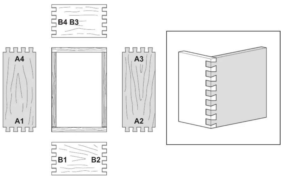
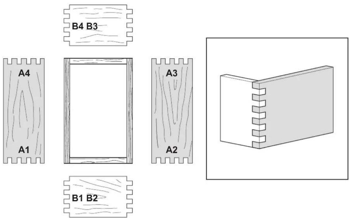
Routing through dovetails (fi g. A2, D2, E1, G & H)
The through dovetail has a look that is visually appealing, especially in boxes and chests. Both tails and pins are cut in the vertical position, in the order given.
Routing the tails
- Place a piece of scrap material of the same thickness as the workpiece intended for the pins part in the horizontal position (fi g. G1).
- Mount the through dovetail/box joint template (41) (fi g. H1). Make sure that the tails side (47) faces the operator.
- Place the workpiece to be used as the tails part in the vertical position (fi g. G2).
- Adjust the left offset guide (9) to centre the pins part relative to the template fi nger spacing as required (fi g. G2). See "Marking and clamping the workpieces".
- Lock the left offset guide in position using the Allen key supplied (36).
- Clamp the workpiece in position.
- Clamp the piece of scrap material in position flush against the workpiece to ensure that the template cannot deflect while the joint is being routed.
- Align the template using the "TAILS/BOX" alignment line (43) (fig. H1 & H3).
- Fit dovetail cutter type A (15) and guide bush type A (17) on the router using a guide bush adaptor plate as required (fi g. A2).
- Adjust the cutter depth using the "TAILS" depth guide (30) (fi g. D2).
- Rout the tails. Remove the workpiece when finished.
Routing the pins
- Place a piece of scrap material of the same thickness as the workpiece intended for the tails part in the horizontal position (fi g. G1).
- Rotate the template (41) through 180^ so that the pins side (48) faces the operator.
- Clamp the workpiece in the vertical position (fi g. G2). Make sure that the workpiece is flush against the left offset guide.
- Clamp the piece of scrap material in position fl ush against the workpiece to ensure that the template cannot defl ect while the joint is being routed.
- Align the template using the "PINS" alignment line (43) (fig. H1 & H3).
- Fit straight cutter type B (16) and guide bush type B (18) on the router using a guide bush adaptor plate as required (fi g. A2).
- Adjust the cutter depth using the "PINS" depth guide (31) (fi g. D2).
- Rout the pins. Remove the workpiece when finished.
- Check the joint.
- If adjustment is required, proceed as follows:
- To make a tighter joint, move the template towards the operator.
- To make a looser joint, move the template away from the operator.
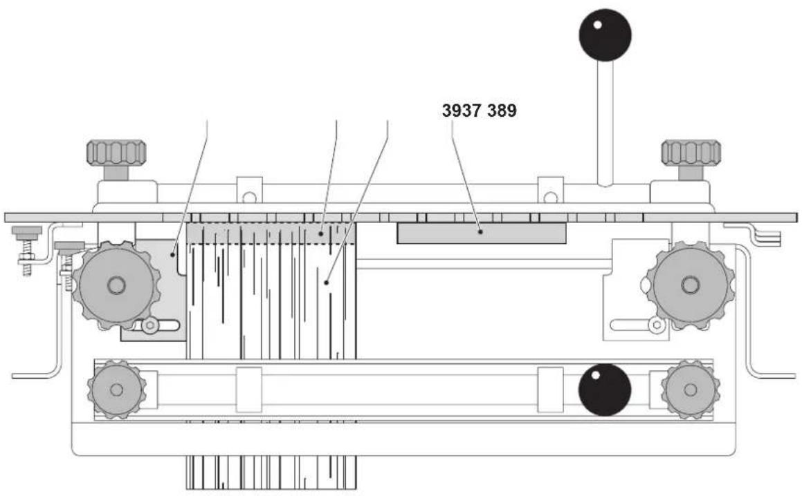
Routing box joints (fi g. A2, D2, E3, G, H & J)
Box joints have straight protrusions that interlock and must be held together by glue. The large amount of gluing surface provides the strength necessary for large projects.
The two joint sections are both cut in the vertical position and in separate operations, the first using the left offset guide and the second the right offset guide
For box joints, a 12.7 mm (1/2") straight cutter (not supplied) is required.
Routing the first joint section
- Place a piece of scrap material of the same thickness as the workpiece intended for the second joint section in the horizontal position (fi g. G1).
- Mount the through dovetail/box joint template (41) (fi g. H1). Make sure that the fingers side (47) faces the operator.
- Place the first workpiece in the vertical position (fi g. G2). Make sure that the outside of the workpiece faces the base of the attachment.
- Adjust the left offset guide (9) to centre the pins part relative to the template fi nger spacing as required (fi g. G2). See "Marking and clamping the workpieces".
- Lock the left offset guide in position using the Allen key supplied (36).
- Clamp the workpiece in position.
- Clamp the piece of scrap material in position fl ush against the workpiece to ensure that the template cannot defl ect while the joint is being routed.
- Align the template using the "TAILS/BOX" alignment line (43) (fi g. H1 & H3).
- Fit a 12.7 mm (1/2") straight cutter and guide bush type A (17) on the router using a guide bush adaptor plate as required (fi g. A2).
- Adjust the cutter depth using the "TAILS" depth guide (30) (fi g. D2).
- Rout the tails with the guide bush against the left side of the fingers of the template, both in and out. Applying light pressure towards the left will help to prevent loose joints.
- Remove the workpiece when finished.
Routing the second joint section
- Place a piece of scrap material of the same thickness as the first workpiece in the horizontal position (fi g. G1).
- Mount the template (41). Make sure that the fingers side (47) faces the operator.
- Loosen the right offset guide (9) using the T-handle Allen key (36). Slide the guide to the far right position (fi g. J).
-
Position the first joint section in the vertical position on the right side of the base. Make sure that the tails protrude through the fingers of the template (fi g. J).
-
Centre the tails of the first joint section between the fingers of the template. Clamp the workpiece into place using the front vice.
- Slide the right offset guide to the left until it is flush against the workpiece. Fasten the offset guide (9).
- Remove the first joint section.
- Clamp the second workpiece in the vertical position (fi g. G2). Make sure that the workpiece is flush against the template and the right offset guide. Make sure that the outside of the workpiece faces the operator.
- Clamp the piece of scrap material in position flush against the workpiece to ensure that the template cannot deflect while the joint is being routed.
- If necessary, adjust the cutter depth using the "TAILS" depth guide (30) (fi g. D2).
- Rout the pins with the guide bush against the left side of the fingers of the template, both in and out. Applying light pressure towards the left will help to prevent loose joints.
- Remove the workpiece when fi nished.
- Assemble the joint.
- The tightness of the joint fit can be adjusted by varying the amount of pressure exerted towards the left during the operation.
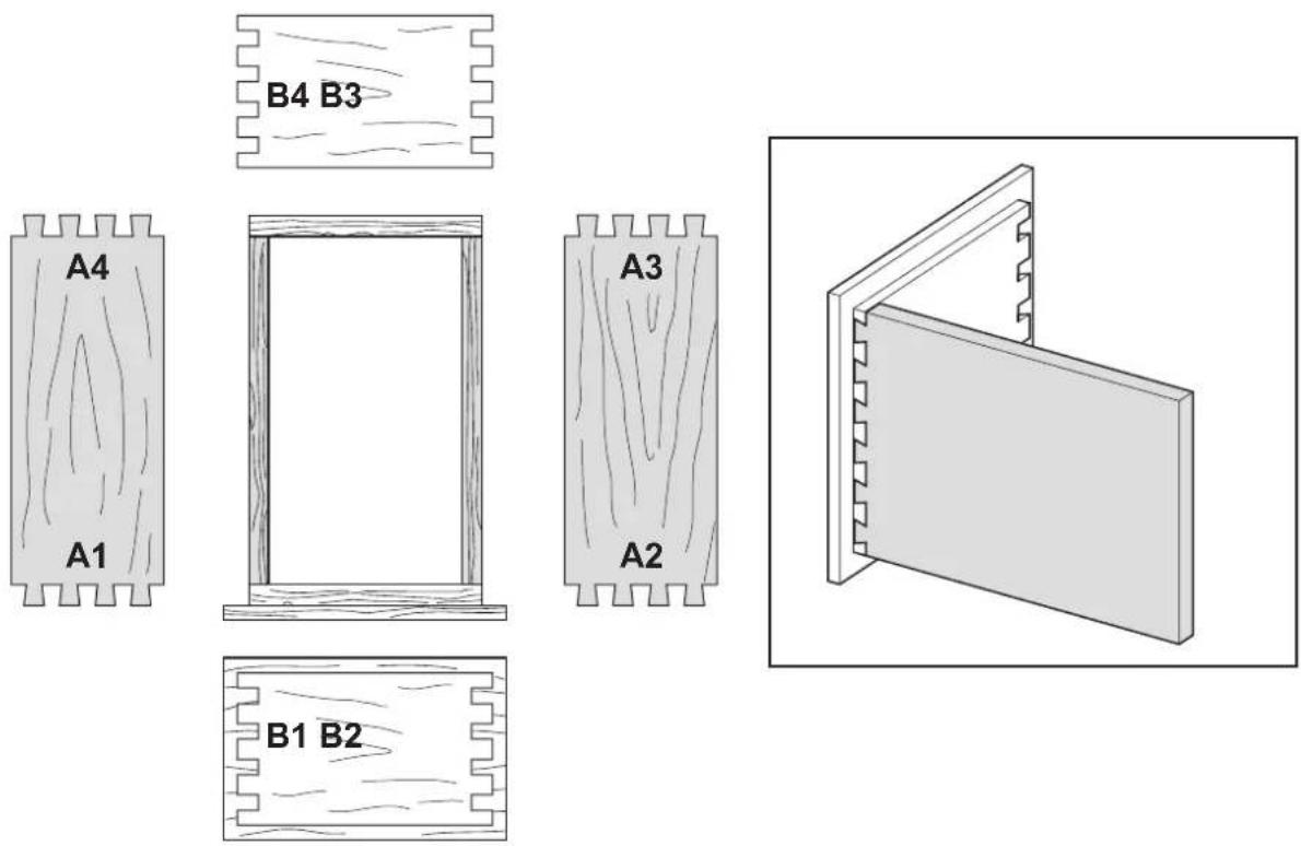
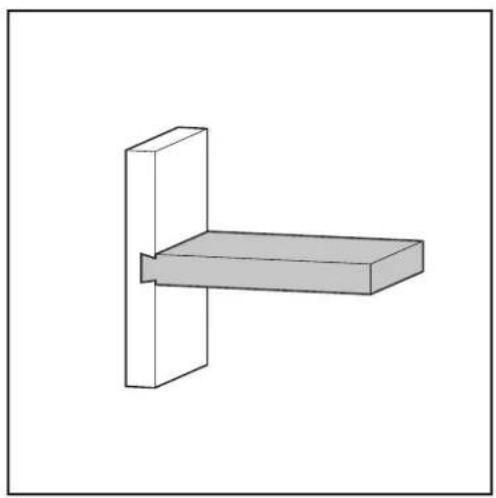
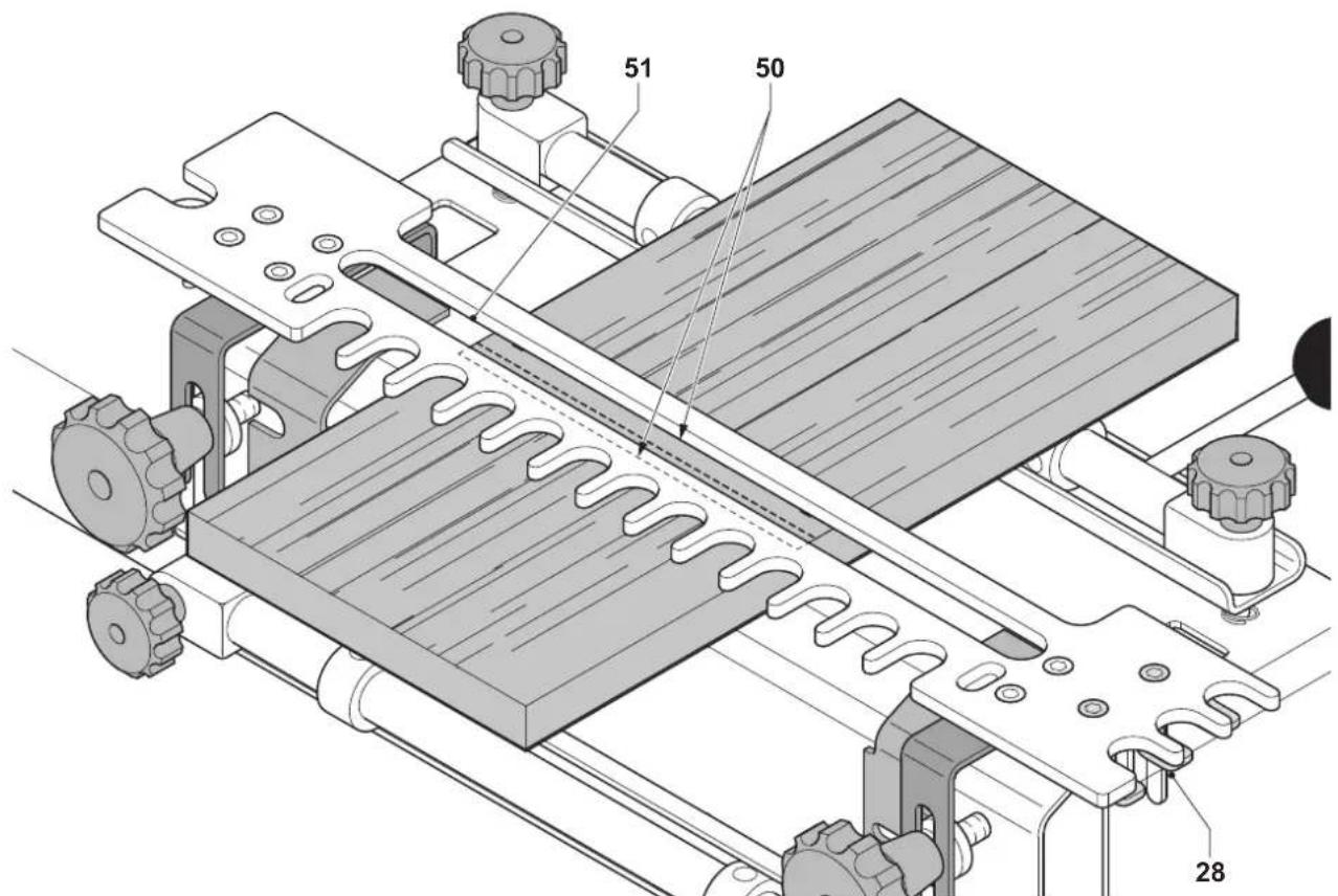
Routing sliding dovetails (fi g. A2, D2, F2, H1 & K1 - K3)
Sliding dovetails (also known as dovetail dados) are used primarily in the construction of shelving and cabinets.
The attachment features 3 preset stops for dado depths of 6.35 mm (1/4"), 9.5 mm (3/8") and 12.7 mm (1/2") (fi g. D2). However, any depth of dado required can be manually created by adjusting the depth setting on your router.
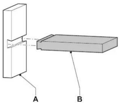
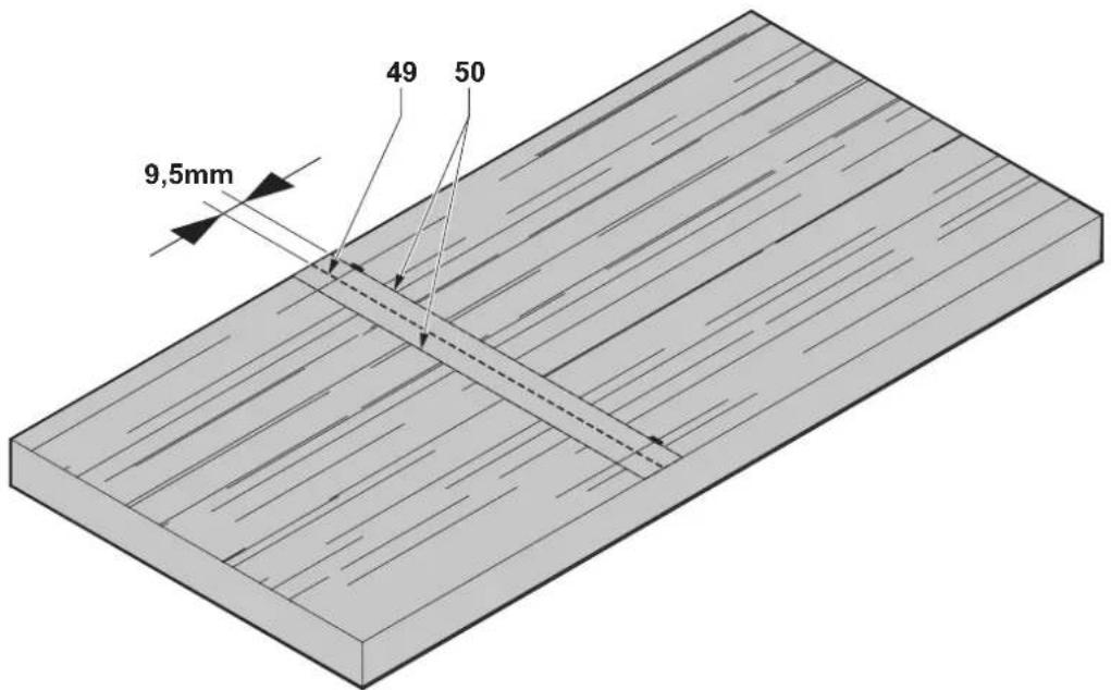
Routing the dado board (A in fig. F2)
- Make sure to prevent the cutter from contacting the base of the attachment.
- Mark the centreline (49) of the dado location on the workpiece intended for the dado board.
- Mark two lines (50) running parallel at 9.5 mm to each side of the centreline
- Place the workpiece in the horizontal position. Make sure that the markings face the operator.
- Mount the template (40). Make sure that the tenon side faces the operator.
- Align the two markings exactly with the edges of the slot (51).
- Fit dovetail cutter type A (15) and guide bush type A (17) on the router using a guide bush adaptor plate as required (fi g. A2).
- Adjust the cutter depth using the selected depth guide (33) (fi g. D2). Alternatively, set the required depth of dado on your router.
- Carefully rout along the slot from left to right.
- Remove the workpiece when fi nished.

In case of routing a deep dado, pre-cut the dado with a straight cutter before routing with the dovetail cutter.
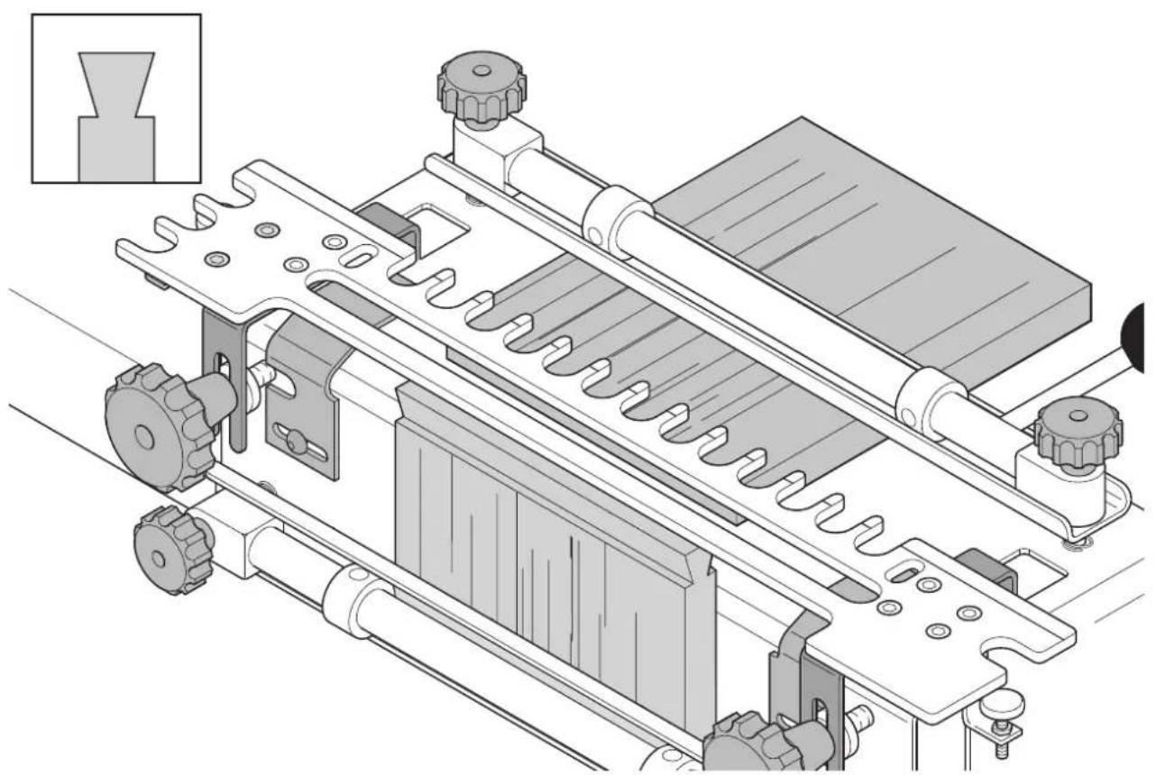
Routing the tenon board (B in fig. F2)
It is recommended to first make a trial cut using scrap material to ensure correct settings.
- Place a piece of scrap material of the same thickness as the dado board in the horizontal position (fi g. K3).
- Place the workpiece intended for the tenon board in the vertical position. Make sure that the edge of the workpiece is flush with the bottom of the template.
- Make a first shallow cut working from right to left across the face of the board to reduce chipping.
- Make a second cut working the router and guide bush along the template edge from right to left to form the profile.
-
Remove the tenon board and turn it through 180°. The cut side of the tenon board will now face the base of the attachment.
-
Repeat the routing operations as described above.
- Remove the workpiece when fi nished.
- Check the joint.
- If adjustment is required, proceed as follows:
- For joints that are too tight, move the template away from the operator and recut the tenon board.
- For joints that are too loose, move the template toward the operator and cut a new tenon board.
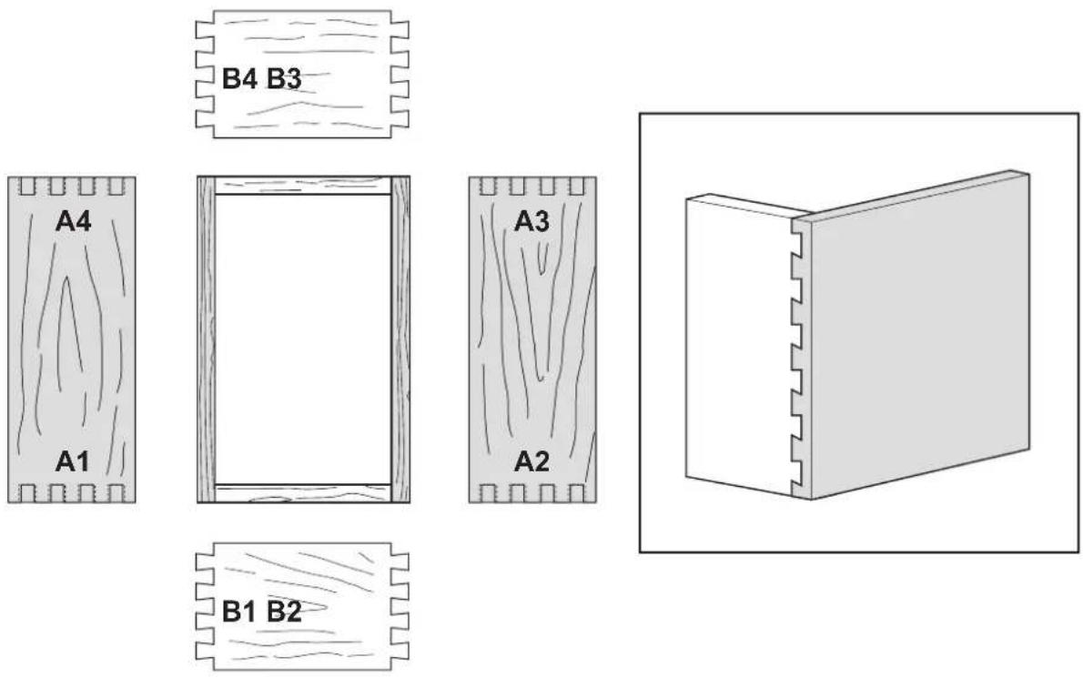
DE6215 Miniature dovetailing template
With this template the attachment is suitable for miniature versions of dovetails. The template provides for through, half-blind and box joints of exactly half the joint spacing of the standard templates.
The package contains:
1 Dovetailing template
2 Brackets
1 Dovetail cutter type C (7.14 mm (9/32"); cutting angle 7°)
1 Straight cutter type D (7.95 mm (5/16"))
1 Guide bush and lock nut type C (9.5 mm (3/8"))
1 Guide bush and lock nut type D (7.95 mm (5/16"))
1 Depth guide bracket
2 Offset guides, silver
1 Depth knob
1 Hex nut
6 Screws
1 Allen key
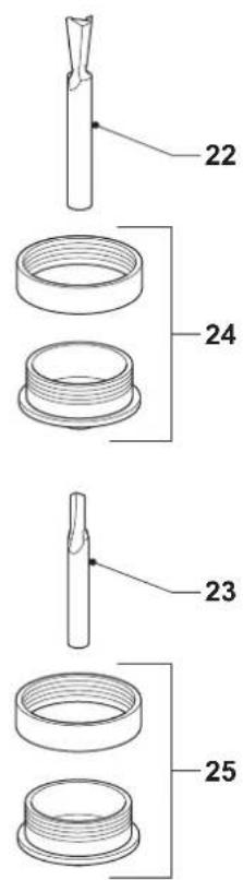
The following accessories are supplied with the template (fi g. A3):
22 Dovetail cutter type C
23 Straight cutter type D
24 Guide bush and lock nut type C
25 Guide bush and lock nut type D
To assemble the template:
- Mount the brackets on the dovetailing template with the screws. Use the supplied Allen key to fasten the screws.
- Mount the depth guide on the template with the screws. Use the supplied Allen key to fasten the screws.
To prepare the dovetailing attachment:
- Replace the standard black offset guides with the silver offset guides.
To use the dovetailing attachment with the miniature template (fi g. H1): In operation, the template (42) is identical to the standard dovetails. However, make the following part substitutions:
- For the tails of through dovetails, use the "TAILS" side (47) of the template with dovetail cutter type C and guide bush type C. Take care to align workpieces with the "TAILS/BOX" alignment line (43).
- For the pins of through dovetails, use the "PINS" side of the template (48) with straight cutter type D and guide bush type D.
- For half-blind dovetails and rebated half-blind dovetails, use the "TAILS" side (47) of the template with dovetail cutter type C and guide bush type C. Take care to align workpieces with the "HALF-BLIND" alignment line (44).
- For box joints, a 6.35 mm (1/4") straight cutter (not supplied) is required. Use the "TAILS" side (47) of the template with a 6.35 mm (1/4") straight cutter and guide bush type C.
Maintenance
Your attachment has been designed to operate over a long period of time with a minimum of maintenance. Continuous satisfactory operation depends upon proper tool care and regular cleaning.

Lubrication
Your attachment requires no additional lubrication.
Protecting the environment

arate collection. This product must not be disposed of with normal household waste.
Should you find one day that your Ⓗ WALT product needs replacement, or if it is of no further use to you, do not dispose of it with household waste. Make this product available for separate collection.

Separate collection of used products and packaging allows materials to be recycled and used again. Re-use of recycled materials helps prevent environmental pollution and reduces the demand for raw materials.
Local regulations may provide for separate collection of electrical products from the household, at municipal waste sites or by the retailer when you purchase a new product.
DEWALT provides a facility for the collection and recycling of DEWALT products once they have reached the end of their working life. To take advantage of this service please return your product to any authorised repair agent who will collect them on our behalf.
You can check the location of your nearest authorised repair agent by contacting your local DE WALT office at the address indicated in this manual. Alternatively, a list of authorised DE WALT repair agents and full details of our after-sales service and contacts are available on the Internet at: www.2helpU.com.
GUARANTEE
• 30 DAY NO RISK SATISFACTION GUARANTEE •
If you are not completely satisfied with the performance of your De WALT tool, simply return it within 30 days, complete as purchased, to the point of purchase, for a full refund or exchange. Proof of purchase must be produced.
• ONE YEAR FREE SERVICE CONTRACT •
If you need maintenance or service for your D E WALT tool, in the 12 months following purchase, it will be undertaken free of charge at an authorized D E WALT repair agent. Proof of purchase must be produced. Includes labour and spare parts for the attachments. Excludes accessories.
- ONE YEAR FULL WARRANTY
If your DEWALT product becomes defective due to faulty materials or workmanship within 12 months from the date of purchase, we guarantee to replace all defective parts free of charge or, at our discretion, replace the unit free of charge provided that:
• The product has not been misused.
• Repairs have not been attempted by unauthorized persons.
• Proof of purchase date is produced.
This guarantee is offered as an extra benefit and is additional to consumers statutory rights.
For the location of your nearest authorized De WALT repair agent, please use the appropriate telephone number on the back of this manual. Alternatively, a list of authorized De WALT repair agents and full details on our after-sales service are available on the Internet at www.2helpU.com.
ACCESORIO PARA UNIÓN A COLA DE MILANO DE6210/DE6212/DE6215
¡Enhorabuena!
Director Engineering and Product Development Horst Großmann

D E WALT, Richard-Klinger-Straße 11, D-65510, Idstein, Alemania
L'emballage contient:
L'emballage contient:
Director Engineering and Product Development Horst Großmann

D E WALT, Richard-Klinger-Straße 11, D-65510, Idstein, Duitsland
Director Engineering and Product Development Horst Großmann

19 Føringshylse, adapterplate for DW613/DW614/DW615
20 Føringshylse, adapterplate for DW620/DW621/DW626
21 Føringshylse, adapterplate for DW624/DW625E/DW629
Tilleggsutstyr
- DE6952 collet-adapter (for DW613/DW614/DW615/DW620/DW621)
- DE6274 collet-adapter (for DW624/DW625E/DW629)
- DE6260 collet-adapter (for DW626)
Director Engineering and Product Development Horst Großmann

D E WALT, Richard-Klinger-Straße 11, D-65510, Idstein, Alemanha
Director Engineering and Product Development Horst Großmann

Director Engineering and Product Development Horst Großmann

Richard-Klinger-Straße 11, D-65510, Idstein, Tyskland