DWFP55120 - Polisher DEWALT - Free user manual and instructions
Find the device manual for free DWFP55120 DEWALT in PDF.

| Product Type | Portable Air Compressor |
| Brand | DeWalt |
| Model | DWFP55120 |
| Tank Capacity | 11.4 L (3 gal) |
| Maximum Pressure | 930.7 kPa (135 psi) |
| Approximate Cut-in Pressure | 723.9 kPa (105 psi) |
| Air Flow @ 90 psi | 1.8 CFM (0.051 m³/min) |
| Power Supply | 120 V, 15 A, 60 Hz |
| Motor Power | Maintenance-Free Universal Motor |
| Recommended Fuse Type | Time-Delay (15 A) |
| Air Outlet | 1/4 in (6.35 mm) Female Tapered Thread |
| Dimensions (approx.) | Not provided |
| Weight (approx.) | Not provided |
| Main Functions | Air compression, pneumatic tool power, inflation |
| Controls | On/Off switch, pressure regulator, tank and outlet pressure gauges |
| Safety System | Safety valve, thermal overload protection, grounding |
| Routine Maintenance | Daily tank draining, safety valve check before each use |
| Included Accessories | Air hose, female inflation adapter, inflation kit |
| Repairability | Authorized DeWalt repair centers, identical replacement parts |
| Warranty | Refer to the manual or DeWalt website |
Frequently Asked Questions - DWFP55120 DEWALT
User questions about DWFP55120 DEWALT
0 question about this device. Answer the ones you know or ask your own.
Ask a new question about this device
Download the instructions for your Polisher in PDF format for free! Find your manual DWFP55120 - DEWALT and take your electronic device back in hand. On this page are published all the documents necessary for the use of your device. DWFP55120 by DEWALT.
USER MANUAL DWFP55120 DEWALT
Definitions: Safety Guidelines
The definitions below describe the level of severity for each signal word. Please read the manual and pay attention to these symbols.
▲ DANGER: Indicates an imminently hazardous situation which, if not avoided, will result in death or serious injury.
▲WARNING: Indicates a potentially hazardous situation which, if not avoided, could result in death or serious injury.
▲ CAUTION: Indicates a potentially hazardous situation which, if not avoided, may result in minor or moderate injury.
NOTICE: Indicates a practice not related to personal injury which, if not avoided, may result in property damage.
Important Safety Instructions
A WARNING: Do not operate this unit until you read and understand this instruction manual for safety, operation and maintenance instructions.
▲ WARNING: This product contains chemicals known to the State of California to cause cancer, and birth defects or other reproductive harm. Wash hands after handling.
⚠ WARNING: Some dust contains chemicals known to the State of California to cause cancer, birth defects or other reproductive harm such as asbestos and lead in lead based paint.
SAVE THESE INSTRUCTIONS
▲ DANGER: RISK OF EXPLOSION OR FIRE T CAN HAPPEN HOW TO PREVENT IT
- It is normal for electrical contacts within the motor and pressure switch to spark.
- If electrical sparks from compressor come into contact with flammable vapors, they may ignite, causing fire or explosion.
• Always operate the compressor in a well ventilated area free of combustible materials, gasoline, or solvent vapors.
- If spraying flammable materials, locate compressor at least 20 feet (6.1 m) away from spray area. An additional length of hose may be required.
- Store flammable materials in a secure location away from compressor.
- Restricting any of the compressor ventilation openings will cause serious overheating and could cause fire.
- Never place objects against or on top of compressor.
- Operate compressor in an open area at least 12" (30.5 cm) away from any wall or obstruction that would restrict the flow of fresh air to the ventilation openings.
- Operate compressor in a clean, dry well ventilated area. Do not operate unit indoors or in any confined area.
- Unattended operation of this product could result in personal injury or property damage. To reduce the risk of fire, do not allow the compressor to operate unattended.

DANGER: RISK TO BREATHING (ASPHYXIATION) WHAT CAN HAPPEN HOW TO PREVENT IT
- The compressed air directly from your compressor is not safe for breathing. The air stream may contain carbon monoxide, toxic vapors, or solid particles from the air tank. Breathing these contaminants can cause serious injury or death.
- Never use air obtained directly from the compressor to supply air for human consumption. The compressor is not equipped with suitable filters and in-line safety equipment for human consumption.
- Exposure to chemicals in dust created by power sanding, sawing, grinding, drilling, and other construction activities may be harmful.
- Sprayed materials such as paint, paint solvents, paint remover, insecticides, weed killers, may contain harmful vapors and poisons.
- Work in an area with good cross ventilation. Read and follow the safety instructions provided on the label or safety data sheets for the materials you are spraying. Always use certified safety equipment: NIOSH/OSHA respiratory protection or properly fitting face mask designed for use with your specific application.

▲ WARNING: RISK OF BURSTING
Air Tank: On February 26, 2002, the U.S. Consumer Product Safety Commission published Release # 02-108 concerning air compressor tank safety:
Air compressor receiver tanks do not have an infinite life. Tank life is dependent upon several factors, some of which include operating conditions, ambient conditions, proper installations, field modifications, and the level of maintenance. The exact effect of these factors on air receiver life is difficult to predict.
If proper maintenance procedures are not followed, internal corrosion to the inner wall of the air receiver tank can cause the air tank to unexpectedly rupture allowing pressurized air to suddenly and forcefully escape, posing risk of injury to consumers.
Your compressor air tank must be removed from service by the end of the year shown on your tank warning label.
The following conditions could lead to a weakening of the air tank, and result in a violent air tank explosion:
WHAT CAN HAPPEN HOW TO PREVENT IT
- Failure to properly drain condensed water from air tank, causing rust and thinning of the steel air tank.
- Drain air tank daily or after each use. If air tank develops a leak, replace it immediately with a new air tank or replace the entire compressor.
- Modifications or attempted repairs to the air tank.
- Never drill into, weld, or make any modifications to the air tank or its attachments. Never attempt to repair a damaged or leaking air tank. Replace with a new air tank.
- Unauthorized modifications to the safety valve or any other components which control air tank pressure.
- The air tank is designed to withstand specific operating pressures. Never make adjustments or parts substitutions to alter the factory set operating pressures.
Attachments & accessories:
- Exceeding the pressure rating of air tools, spray guns, air operated accessories, tires, and other inflatables can cause them to explode or fly apart, and could result in serious injury.
- Follow the equipment manufacturers recommendation and never exceed the maximum allowable pressure rating of attachments. Never use compressor to inflate small low pressure objects such as children's toys, footballs, basketballs, etc.
Tires:
• Over inflation of tires could result in serious injury and property damage.
- Use a tire pressure gauge to check the tires pressure before each use and while inflating tires; see the tire sidewall for the correct tire pressure.
NOTE: Air tanks, compressors and similar equipment used to inflate tires can fill small tires very rapidly. Adjust pressure regulator on air supply to no more than the rating of the tire pressure. Add air in small increments and frequently use the tire gauge to prevent over inflation.

▲ WARNING: RISK OF ELECTRICAL SHOCK
WHAT CAN HAPPEN HOW TO PREVENT IT
- Your air compressor is powered by electricity. Like any other electrically powered device, If it is not used properly it may cause electric shock.
• Never operate the compressor outdoors when it is raining or in wet conditions.
- Never operate compressor with protective covers removed or damaged.
• Repairs attempted by unqualified personnel can result in serious injury or death by electrocution.
- Electrical Grounding:
Failure to provide adequate grounding to this product could result in serious injury or death from electrocution. See Grounding Instructions under Installation.
- Any electrical wiring or repairs required on this product should be performed by a DEWALT factory service center or a DEWALT authorized service center in accordance with national and local electrical codes.
- Make certain that the electrical circuit to which the compressor is connected provides proper electrical grounding, correct voltage and adequate fuse protection.

▲ WARNING: RISK FROM FLYING OBJECTS
WHAT CAN HAPPEN HOW TO PREVENT IT
- The compressed air stream can cause soft tissue damage to exposed skin and can propel dirt, chips, loose particles, and small objects at high speed, resulting in property damage or personal injury.
- Always wear certified safety equipment: ANSI Z87.1 eye protection (CAN/CSA Z94.3) with side shields when using the compressor.
- Never point any nozzle or sprayer toward any part of the body or at other people or animals.
- Always turn the compressor off and bleed pressure from the air hose and air tank before attempting maintenance, attaching tools or accessories.

⚠ WARNING: RISK OF HOT SURFACES CAN HAPPEN HOW TO PREVENT IT
- Touching exposed metal such as the compressor head, engine head, engine exhaust or outlet tubes, can result in serious burns.
- Never touch any exposed metal parts on compressor during or immediately after operation. Compressor will remain hot for several minutes after operation. - Do not reach around protective shrouds or attempt maintenance until unit has been allowed to cool.
▲ WARNING: RISK FROM MOVING PARTS
WHAT CAN HAPPEN HOW TO PREVENT IT
- Moving parts such as the pulley, flywheel, and belt can cause serious injury if they come into contact with you or your clothing.
- Never operate the compressor with guards or covers which are damaged or removed.
- Keep your hair, clothing, and gloves away from moving parts. Loose clothes, jewelry, or long hair can be caught in moving parts.
• Air vents may cover moving parts and should be avoided as well. - Any repairs required on this product should be performed by a DEWALT factory service center or a DEWALT authorized service center.

▲ WARNING: RISK OF UNSAFE OPERATION
WHAT CAN HAPPEN HOW TO PREVENT IT
- Unsafe op er a tion of your air • compressor could lead to se ri ous in ju ry or death to you or others.
Review and understand all instructions and warnings in this manual.
- Be come fa mil iar with the operation and con trols of the air compressor.
- Keep operating area clear of all persons, pets, and obstacles.
- Keep chil dren away from the air compressor at all times.
- Do not operate the product when fatigued or under the influence of alcohol or drugs. Stay alert at all times.
- Never defeat the safety features of this product.
• Equip area of operation with a fire extinguisher.
- Do not operate machine with missing, broken, or unauthorized parts.
• Never stand on the compressor

▲ WARNING: RISK OF FALLING
WHAT CAN HAPPEN HOW TO PREVENT IT
- A portable compressor can fall from a table, workbench, or roof causing damage to the compressor and could result in serious injury or death to the operator.
- Always operate compressor in a stable secure position to prevent accidental movement of the unit. Never operate compressor on a roof or other elevated position. Use additional air hose to reach high locations.

CAUTION: RISK FROM NOISE
WHAT CAN HAPPEN HOW TO PREVENT IT
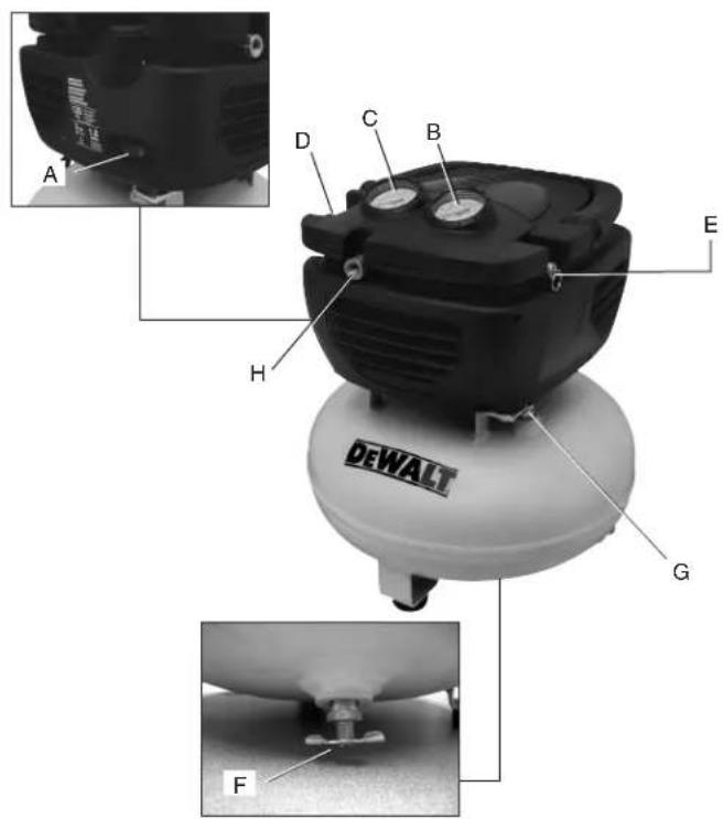
DWFP55120 Air Compressor
A. On(I)/Off(O)Switch
B. Tank Pressure Gauge
C. Outlet Pressure Gauge
D.Regulator
E.SafetyValve
F. Drain Valve
G.CheckValve
H. Air Outlet (1/4" NPTF)
Pump/Motor Specifications
Maintenance free universal motor
Voltage: Single 120V
Minimum branch circuit requirement: 15 A
Fuse Type: Time delay
Specifications
| MODEL | DWFP55120 |
| AIR TANK CAPACITY | 3 gallons (11.4 liters) |
| APPROX CUT-IN PRESSURE | 105 psi |
| APPROX. CUT-OUT PRESSURE | 135 psi |
| SCFM @ 90 PSI | 1.8 |
Fig. 1
• Under some conditions and Always wear proper hearing duration of use, noise from this product may contribute to hearing loss.
SAVE THESE INSTRUCTIONS FOR FUTURE USE
FEATURES
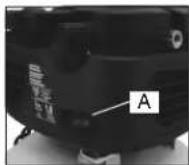
ON (I) /OFF SWITCH (O)
Place this switch (A) in the ON position to provide automatic power to the pressure switch and OFF to remove power at the end of each use.
PRESSURE SWITCH (NOT SHOWN)
The pressure switch automatically starts the motor when the air tank pressure drops below the factory set cut-in pressure. It stops the motor when the air tank pressure reaches the factory set cut-out pressure.
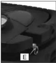
SAFETY VALVE
If the pressure switch does not shut off the air compressor at its cut-out pressure setting, the safety valve (E) will protect against high pressure by popping out at its factory set pressure (slightly higher than the pressure switch cut-out setting).
natural_image
Close-up of a mechanical component with a small labeled feature 'E' (no readable text or symbols beyond the label)CHECK VALVE
When the air compressor is operating, check valve (G) is open, allowing compressed air to enter the air tank. When the air compressor reaches cut-out pressure, the check valve closes, allowing air pressure to remain inside the air tank.
TANK PRESSURE GAUGE
natural_image
Close-up of a mechanical component with a small attached piece, labeled 'G' (no readable text or symbols)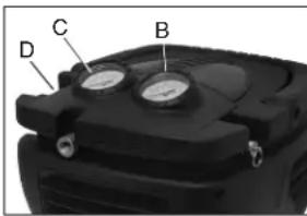
The tank pressure gauge (B) indicates the reserve air pressure in the tank.
OUTLET PRESSURE GAUGE
The outlet pressure gauge (C) indicates the air pressure available at the outlet side of the regulator. This pressure is controlled by the regulator
and is always less than or equal to the tank pressure.
REGULATOR
The regulator (D) controls the air pressure shown on the outlet pressure gauge. Turn regulator knob clockwise to increase pressure and counterclockwise to decrease pressure.
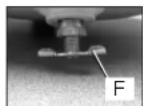
DRAIN VALVE
The drain valve (F) is located at the base of the air tank and is used to drain condensation at the end of each use. See Draining Air Tank under Maintenance.
COOLING SYSTEM
This compressor contains an advanced design cooling system. It is normal for this fan to blow air through the vent holes in large amounts. The cooling system is working when air is expelled.
AIR COMPRESSOR PUMP
The pump compresses air into the air tank. Working available until the compressor has raised the air tank pressure above that required at the air outlet.
MOTOR OVERLOAD PROTECTOR (NOT SHOWN)
The motor has thermal overload protector. If the motor overheats for any reason, the overload protector will shut off the motor. The motor must be allowed to cool down before restarting.
TO RESTART:
- Set the on/off switch to "O" and unplug unit.
- Allow the motor to cool.
- Plug the power cord into the correct branch circuit receptacle.
- Set the on/off switch to "I" position.
ASSEMBLY
CONTENTS OF CARTON
1 - Air Compressor
1 - Air Hose
1 - Female Tire Chuck
1 - Inflator Accessory Kit
TOOLS REQUIRED FOR ASSEMBLY
1 - Adjustable wrench
UNPACKING
Remove unit from carton and discard all packaging. NOTE: Save all parts bags.
ASSEMBLE HOSE
- Ensure regulated pressure guage reads 0 psi.
- Assemble hose to air outlet. (H)
ASSEMBLE ACCESSORIES (FIG. 2)
⚠ WARNING: To reduce the risk of injury, turn unit off and disconnect it from power source before installing and removing accessories, before adjusting or when making repairs. An accidental start-up can cause injury.
Choose the accessory needed.
NOTE: Apply thread seal tape to threads of exposed fittings.
Assemble Female Tire Chuck
- Ensure regulated pressure gauge read 0 psi.
- Assemble female tire chuck to hose and tighten securely with wrenches.
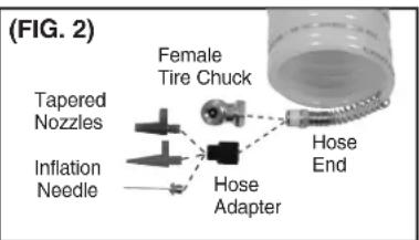
Assemble Other Accessories
- Ensure regulated pressure gauge read 0 psi.
- Attach the hose adapter to hose.
- Choose the needed accessory. Attach the tapered nozzles, needle or high flow inflator/deflator adapter body to the hose adapter.
Grounding Instructions
▲ WARNING: Risk of electrical shock. In the event of a short circuit, grounding reduces the risk of shock by providing an escape wire for the electric current. This air compressor must be properly grounded.
The portable air compressor is equipped with a cord having a grounding wire with an appropriate grounding plug.
- The cord set and plug (J) with this unit contains a grounding pin (L). This plug MUST be used with a grounded outlet (K).
IMPORTANT: The outlet being used must be installed and grounded in accordance with all local codes and ordinances.
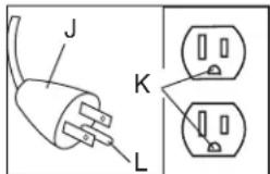
- Ensure the outlet being used has the same configuration as the grounded plug. DO NOT USE AN ADAPTER.
- Inspect the plug and cord before each use. Do not use if there are signs of damage.
- If these grounding instructions are not completely understood, or if in doubt as to whether the compressor is properly grounded, have the installation checked by a qualified electrician.
▲ DANGER: RISK OF ELECTRICAL SHOCK. IMPROPER GROUNDING CAN RESULT IN ELECTRICAL SHOCK.
- Do not modify the plug provided. If it does not fit the available outlet, a correct outlet should be installed by a qualified electrician.
- Repairs to the cord set or plug MUST be made by a qualified electrician.
Extension Cords
If an extension cord must be used, be sure it is:
- a 3-wire extension cord that has a 3-blade grounding plug, and a 3-slot receptacle that will accept the plug on the product
• in good condition
• no longer than 50' (15.2 m)
• 14 gauge (AWG) or larger. (Wire size increases as
number decreases. 12 AWG and 10 AWG may also be used. DO NOT USE 16 OR 18 AWG.)
NOTICE: Risk of Property Damage. The use of an undersized extension cord will cause voltage to drop resulting in power loss to the motor and overheating. Instead of using an extension cord, increase the working reach of the air hose by attaching another length of hose to its end. Attach additional lengths of hose as needed.
Voltage and Circuit Protection
Refer to the Voltage and Minimum Branch Circuit Requirements under Pump/Motor Specifications.
▲ CAUTION: Risk of Overheating. Certain air compressors can be operated on a 15 amp circuit if the following conditions are met.
- Voltage supply to circuit must comply with the National Electrical Code.
• Circuit is not used to supply any other electrical needs.
• Extension cords comply with specifications. - Circuit is equipped with a 15 amp circuit breaker time delay fuse. NOTE: If compressor is connected to a circuit protected by fuses, use only time delay fuses. Time delay fuses should be marked "D" in Canada and "T" in the US.
If any of the above conditions cannot be met, or if operation of the compressor repeatedly causes interruption of the power, it may be necessary to operate it from a 20 amp circuit. It is not necessary to change the cord set.
Compatibility
Air tools and accessories that are run off the compressor must be compatible with petroleum-based products. If you suspect that a material is not compatible with petroleum products, an air line filter for removal of moisture and oil vapor in compressed air is required.
NOTE: Always use an air line filter to remove moisture and oil vapor when spraying paint.
Location
Place the air compressor in a clean, dry and well ventilated area at least 12" (30.5 cm) away from the wall or other obstructions that will interfere with the flow of air. Keep the compressor away areas that have dirt and/or volatile fumes in the atmosphere. These impurities may clog the intake filter and valves, causing inefficient operation.
The air compressor pump and shroud are designed to allow for proper cooling. The ventilation openings on the compressor are necessary to maintain proper operating temperature. Do not place rags or other containers on or near these openings.
Place the air compressor on a flat surface resting on the rubber feet.
NOISE CONSIDERATIONS
Consult local officials for information regarding acceptable noise levels in your area. To reduce excessive noise, use vibration mounts or silencers, relocate the unit or construct total enclosures or baffle walls. Contact a DEWALT service center.
ELECTRICAL
Refer to all safety instructions before using unit. Observe extension cord safety instructions if necessary. Always move the On/Off switch (A) to the OFF position before removing the plug from the outlet.
TRANSPORTING
When transporting the compressor in a vehicle, trailer, etc., ensure that the tank is drained and the unit is secured. Use care when driving to avoid tipping the unit over in the vehicle. Damage can occur to the compressor or surrounding items if the compressor is tipped.
MOVING
When moving the compressor, grasp the handle and compressor as close to the body as possible.
▲ WARNING: Risk of unsafe operation. Ensure proper footing and use caution when carrying compressor to avoid a loss of balance.
PREPARATION FOR USE
Pre-Start Checklist (Fig. 1)
- Ensure the On/Off switch (A) is in the OFF position.
- Plug the power cord into the correct branch circuit receptacle. See Voltage and Circuit Protection under Installation.
- Ensure air tank is drained, see Draining Air Tank under Maintenance.
- Ensure the drain valve (G) is closed.
- Ensure safety valve (F) is functioning properly, see Checking Safety Valve under Maintenance.
- Turn regulator knob (D) counterclockwise until fully closed. Ensure regulated pressure gauge reads 0 psi.
-
Visually inspect air hose, replace if needed.
-
Attach hose and accessories.
▲ WARNING: Risk of unsafe operation. Firmly grasp air hose in hand when installing or disconnecting to prevent hose whip.
⚠ WARNING: Risk of unsafe operation. Do not use damaged or worn accessories.
▲ WARNING: Risk of bursting. Too much air pressure causes a hazardous risk of bursting. Check the manufacturer's maximum pressure rating for air tools and accessories. The regulator outlet pressure must never exceed the maximum pressure rating.
OPERATING PROCEDURES
▲ WARNING: Do not operate this unit until you read and understand this instruction manual for safety, operation and maintenance instruction
Start-up (Fig. 1)
- Follow Pre-Start Checklist under Preparation for Use.
- Move the On/Off switch to the ON position and allow tank pressure to build. Motor will stop when tank pressure reaches cut-out pressure.
▲ CAUTION: Risk of unsafe operation. Compressed air from the unit may contain wa ter condensation. Do not spray un fil tered air at an item that could be damaged by moisture. Some air op er ated tools or de vic es may require filtered air. Read the in struc tions for the air tool or device.
- Adjust regulator (D) to desired setting. See Regulator under Features.
Shut-down (Fig. 1)
- Move On/Off switch (A) to the OFF position. NOTE: If finished using compressor, follow Steps 2–6.
NOTE: When the unit has been turned off, it is normal to hear a short hiss of air being released.
-
Turn regulator knob (D) counterclockwise until fully closed. Ensure regulated pressure gauge reads 0 psi.
-
Remove hose and accessory.
NOTE: Always turn off and unplug unit when not in use.
⚠ WARNING: Risk of unsafe operation. Firmly grasp air hose in hand when installing or disconnecting to prevent hose whip.
- Drain the air tank, see Draining Air Tank under Maintenance. Ensure air tank pressure gauge reads 0 psi.
▲ WARNING: Risk of bursting. Drain air tank daily. Water will
condense in air tank. If not drained, water will corrode and weaken the air tank causing a risk of air tank rupture.
- Allow the compressor to cool down.
- Wipe air compressor clean and store in a safe, non-freezing area.
MAINTENANCE
The following procedures must be followed when maintenance or service is performed on the air compressor.
- Ensure On/Off switch is in the OFF position.
- Remove air compressor plug from outlet.
- Drain air tank.
- Allow air compressor to cool down before starting service.
NOTE: All compressed air systems contain maintenance parts (e.g., oil, filters, separators) that are periodically replaced. These used parts may contain substances that are regulated and must be disposed of in accordance with local, state, and federal laws and regulations.
NOTE: Take note of the positions and locations of parts during disassembly to make reassembly easier.
NOTE: Any service operations not included in this section should be performed by a DEWALT factory service center eWALT authorized service center.
Maintenance Chart
| Procedure Before Each Use | Daily or after each use | See tank warning label | |
| Check safety valve | X | ||
| Drain air tank | X | ||
| Remove tank from service | X^1 | ||
| 1- For more information, call 1-800-4-DEWALT (1-800-433-9258) | |||
Checking Safety Valve
▲WARNING: Risk of bursting. If the safety valve does not work properly, over-pressurization may occur, causing air tank rupture or an explosion.
Before starting compressor, pull the ring on the safety valve to make sure that the safety valve operates freely. If the valve is stuck or does not operate smoothly, it must be replaced with the same type of valve.
To Drain Tank
▲WARNING: Risk of Unsafe Operation. Risk from noise. Air tanks contain high pressure air. Keep face and other body parts away from outlet of drain. Use ANSI Z87.1 eye protection (CAN/CSA Z94.3) when draining as debris can be kicked up into face.
▲WARNING: Risk from noise. Use ear protection [(ANSI S12.6 (S3.19) hearing protection] as air flow noise is loud when draining.
NOTE: All compressed air systems generate condensate that accumulates in any drain point (e.g., tanks, filter, aftercoolers, dryers). This condensate contains lubricating oil and/or substances which may be regulated and must be disposed of in accordance with local, state, and federal laws and regulations.
- Ensure On/Off switch (A) is in the OFF position.
- Turn the regulator knob counter-clockwise to set the outlet pressure to zero.
- Remove the air tool or accessory.
- Pull ring on safety valve allowing air to bleed from the tank until tank pressure is approximately 20 psi. Release safety valve ring.
- Drain water from air tank by opening drain valve (G) on bottom of tank.
▲ WARNING: Risk of Bursting. Water will condense in the air tank. If not drained, water will corrode and weaken the air tank causing a
risk of air tank rupture.
NOTICE: Risk of Property Damage. Drain water from air tank may contain oil and rust which can cause stains.
- After the water has been drained, close the drain valve. The air compressor can now be stored.
NOTE: If drain valve is plugged, release all air pressure. The valve can then be removed, cleaned, the reinstalled.
ACCESSORIES
Recommended accessories for use with your tool are available for purchase from your local dealer or authorized service center.
⚠ WARNING: The use of any other accessory not recommended for use with this tool could be hazardous. Use only accessories rated equal to or higher than the rating of the air compressor.
Repairs
To assure product SAFETY and RELIABILITY, repairs, maintenance and adjustment should be performed EWALT a factory service center, a DEWALT authorized service center or other qualified service personnel. Always use identical replacement parts.
GLOSSARY
CFM: Cubic feet per minute.
SCFM: Standard cubic feet per minute; a unit of measure of air delivery.
PSI: Pounds per square inch; a unit of measure of pressure.
Code Certification: Products that bear one or more of the following marks: UL ^® , CUL, CULUS, ETL ^®* , CETL, CETLUS have been evaluated by OSHA certified independent safety laboratories and meet the applicable Standards for Safety.
*UL® is a registered trademark of Underwriters Laboratories and ETL® is a registered trademark of Electrical Testing Laboratories.
Cut-In Pressure: While the motor is off, air tank pressure drops when accessory is used. When the tank pressure drops to a certain low level the motor will restart automatically. The low pressure at which the motor automatically restarts is called cut-in pressure.
Cut-Out Pressure: When an air compressor is turned begins to run, air pressure in the air tank begins to build. It builds to a certain high pressure before the motor automatically shuts off, protecting your air tank from pressure higher than its capacity. The high pressure at which the motor shuts off is called cut-out pressure.
Branch Circuit: The circuit carrying electricity from electrical panel to outlet.
Duty Cycle: This air compressor pump is capable of running continuously. However, to prolong the life of your air compressor, it is recommended that a 50%-75% average duty cycle be maintained; that is, the air compressor pump should not run more than 30–45 minutes in any given hour.
Troubleshooting Guide
This section provides a list of the more frequently encountered malfunctions, their causes and corrective actions. The operator or maintenance personnel can perform some corrective actions, and others may require the assistance of a qualified DEWALT technician or your dealer.
Problem Code
Excessive air tank pressure-safety valve pops off 1,2
Air leaks 3
Air leaks in air tank or at air tank welds 4
Air leaks between head and valve plate....5
Air leaks from safety valve....6
Knocking Noise....6
Pressure reading on the regulated pressure gauge drops when an accessory is used ......7
Compressor is not supplying enough air to operate accessories....8, 9, 10, 11, 12
Regulator knob has continuous air leak 13
Regulator will not shut off air outlet 13
Motor will not run....14, 15, 16, 17, 18, 19
Troubleshooting Codes
| CODE | POSSIBLE CAUSE POSSIBLE SOLUTION | |
| 1 | Pressure switch does not shut off motor when compressor reaches cut-out pressure | Set the On/Off switch to OFF, if the unit does not shut off contact a DEWALT factory service center or a DEWALT authorized service center. |
| 2 | Pressure switch cut-out too high | Contact a DEWALT factory service center or a DEWALT authorized service center. |
| 3 | Tube fittings are not tight enough | Tighten fittings where air can be heard escaping. Check fittings with soapy water solution.Do Not Overtighten. |
| 4 | Defective air tank Air tank must be replaced. Do not repair the leak.⚠ WARNING:Risk of bursting. Do not drill into, weld or otherwise modify air tank or it will weaken. The air tank can rupture or explode. | |
| 5 | Leaking seals Contact a D | EWALT factory service center or a DEWALT authorized service center. |
| 6 | Defective safety valve | Operate safety valve manually by pulling on ring. If valve still leaks, it must be replaced. |
| 7 | Regulator is not adjusted correctly for accessory being used | It is normal for some pressure drop to occur when an accessory is used, adjust the regulator as instructed in Regulator under Features if pressure drop is excessive.NOTE: Adjust the regulated pressure under flow conditions while accessory is being used. |
| 8 | Prolonged excessive use of air Decrease amount | of air usage. |
| 9 | Compressor is not large enough for accessory | Check the accessory air requirement. If it is higher than the CFM or pressure supplied by your air compressor, a larger compressor is needed to operate accessory. |
| 10 | Hole in air hose Replace air hose. | |
| 11 | Check valve restricted Contact a D | EWALT factory service center DWALat Authorized service center. |
| 12 | Air leaks Tighten fittings. | |
| 13 | Regulator is damaged Replace. | |
| 14 | Motor overload protection switch has tripped | See Motor Overload under Features. |
| 15 | Extension cord is wrong length or gauge | Check for proper gauge wire and cord length. See Extension Cords under Installation. |
| 16 | Loose electrical connections | Contact a DEWALT factory service center DWALat Authorized service center. |
| 17 | Possible defective motor. | Contact a DEWALT factory service center DWALat Authorized service center. |
| 18 | Fuse blown, circuit breaker tripped | Check fuse box for blown fuse and replace as necessary. Reset circuit breaker. Do not use a fuse or circuit breaker with higher rating than that specified for your particular branch circuit.Check for proper fuse. Use only a time delay fuse.Check for low voltage conditions and/or proper extension cord.Disconnect the other electrical appliances from circuit or operate the compressor on its own branch circuit. |
| 19 | Tank pressure exceeds pressure switch cut-in pressure | Motor will start automatically when tank pressure drops below cut-in pressure of pressure switch. |
natural_image
Close-up of a mechanical component with a small circular feature labeled 'E' (no readable text or symbols)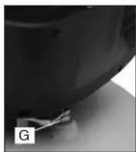
natural_image
Close-up of a dark, curved surface with a small object near the edge (no visible text or symbols)Eje Central Lázaro Cárdenas No. 18 Local D, Col. Obrera (55) 5588 9377
MERIDA, YUC
Calle 63 #459-A - Col. Centro (999) 928 5038
MONTERREY, N.L.
Av. Francisco I. Madero 831 Poniente - Col. Centro (818) 375 23 13
PUEBLA, PUE
17 Norte #205 - Col. Centro (222) 246 3714
QUERETARO, QRO
Av. San Roque 274 - Col. San Gregorio (442) 2 17 63 14
SAN LUIS POTOSI, SLP
CONSERVER CES INSTRUCTIONS POUR LA CONSULTATION ULTÉRIEURE
CARACTÉRISTIQUES
INTERRUPTEUR MARCHE (I)/ARRÊT (O)
natural_image
Close-up of a car tire with a key inserted, no visible text or symbolsCLAPET ANTIRETOUR
natural_image
Close-up of a mechanical component with a small attached part, labeled 'G' in the corner (no other text or symbols visible)MANOMÈTRE DU RÉSERVOIR
DEWALT Industrial Tool Co., 701 Joppa Road, Baltimore, MD 21286
(JAN12) Part No. N166061 DWFP55120 Copyright © 2009, 2010, 2012 D EWALT
The following are trademarks for one or more DEWALT power tools: the yellow and black color scheme; the "D" shaped air intake grill; the array of pyramids on the handgrip; the kit box configuration; and the array of lozenge-shaped humps on the surface of the tool.