DXSP190612 - Paint spray DEWALT - Free user manual and instructions
Find the device manual for free DXSP190612 DEWALT in PDF.

| Product Type | Manual Pump Sprayer |
| Brand | DeWalt |
| Model | DXSP190612 |
| Tank Capacity | 7.5 L |
| Lance Length | 21" (53.3 cm) |
| Hose Material | Ultra-durable Reinforced Nylon |
| Nozzle Type | Adjustable brass nozzle + fan nozzles included |
| Key Features | Chemical spraying, continuous or adjustable spray, trigger lock |
| Power Source | Manual (hand pump) |
| Operating Pressure | Manual pressure (do not use compressor) |
| Maintenance and Cleaning | Rinse with clean water after each use, lubricate O-rings with petroleum jelly, depressurize before maintenance |
| Safety | Do not use flammable products, wear PPE (safety glasses, gloves, clothing), depressurize before disassembly |
| Spare Parts and Repairability | Original replacement parts available (seals, valves, nozzles), replaceable shut-off device |
| Warranty | 3 years against material and workmanship defects |
| Approximate Weight | 2.5 kg |
| Approximate Dimensions (L x W x H) | 30 x 20 x 40 cm |
Frequently Asked Questions - DXSP190612 DEWALT
User questions about DXSP190612 DEWALT
0 question about this device. Answer the ones you know or ask your own.
Ask a new question about this device
Download the instructions for your Paint spray in PDF format for free! Find your manual DXSP190612 - DEWALT and take your electronic device back in hand. On this page are published all the documents necessary for the use of your device. DXSP190612 by DEWALT.
USER MANUAL DXSP190612 DEWALT
If you have questions or comments, contact us.
English (original instructions) 1
Definitions: Safety Alert Symbols and Words
This instruction manual uses the following safety alert symbols and words to alert you to hazardous situations and your risk of personal injury or property damage.

ER: Indicates an imminently hazardous situation which, if not avoided, will result in death or serious injury.

ING: Indicates a potentially hazardous situation which, if not avoided, could result in death or serious injury.

ON: Indicates a potentially hazardous situation which, if not avoided, may result in minor or moderate injury.

without word) Indicates a safety related message.
NOTICE: Indicates a practice not related to personal injury which, if not avoided, may result in property damage.

ING! Read all safety warnings

II instructions. Failure to follow
the warnings and instructions may result in serious injury.

WARNING: To reduce the risk of injury, read the instruction manual.
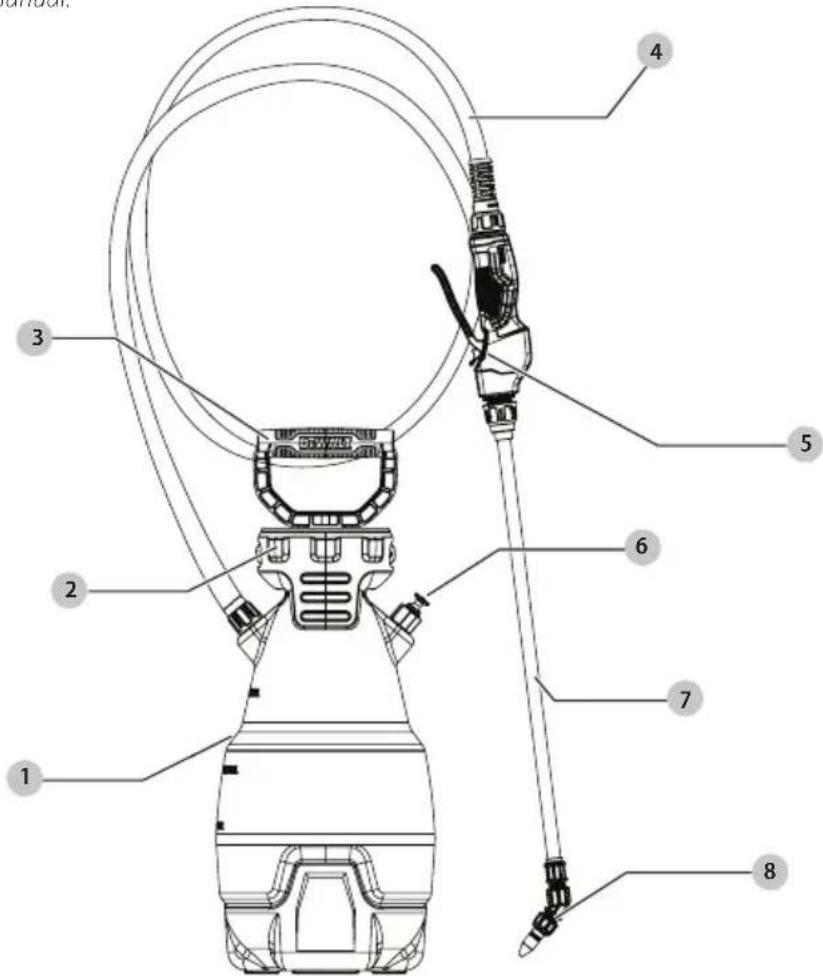
1 Tank
2 Tank Collars
3 Pump
4 Heavy Duty Nylon Reinforced Hose
5 Professional Ergonomic Shut-off
6 Pressure Release Valve (PRV)
7 21" Heavy Duty Non-Corrosive Wand
8 Adjustable Brass Nozzle (Fan Nozzles also included)
IMPORTANT SAFETY INSTRUCTIONS
DANGER: RISK OF DEATH, SEVERE PERSONAL INJURY AND/OR PROPERTY DAMAGE FROM IMPROPER CHEMICAL USE OR MIXTURE.
- Never use flammable or combustible chemicals in this sprayer. Spraying flammable or combustible chemicals can create combustible fumes that could be ignited, causing an explosion.
- Use only chemicals indicated for spraying applications. Some chemicals may create a toxic or other hazardous atmosphere when sprayed.
- Always refer to chemical manufacturer's instructions and/or the chemical Safety Data Sheet (SDS) for proper mixture and safe application.
WARNING: RISK OF PERSONAL INJURY AND/OR PROPERTY DAMAGE DUE TO CHEMICAL EXPOSURE.
- Read and understand the entire instruction manual before using this sprayer.
- Follow all instructions and precautions in the instruction manual when using this sprayer.
- Read and follow all instructions and precautions on chemical manufacturer's label of chemicals used in this sprayer.
- Use the appropriate Personal Protective Equipment (PPE) as recommended by the chemical manufacturer and/or refer to the chemical Safety Data Sheet (SDS) of the chemical being used. This includes at least goggles, gloves, and protective clothing. Failure to use appropriate PPE could result in chemical exposure through skin contact, eye contact, inhalation, or other means.
• After initial assembly, extended storage, or any possibly damaging event, such as a fall, always inspect the sprayer for damage, and test it with plain water to check for proper function. Ensure all connections are secure and leak free, and the hose is free from damage, prior to using the sprayer with chemical.
- Always inspect the hose and all connections before each use. A damaged hose or loose connections could result in an uncontrolled high pressure discharge of chemical.
- Do not spray near open flame, hot surfaces, or anything that could vaporize the spray. Doing so could create a dangerous chemical atmosphere.
- Never use caustics, bleach, acids, hot water, or pressure producing chemicals in this sprayer.
- Keep the sprayer and all chemicals out of the reach of children and pets.
- Only spray when the air is calm (no wind or air movement) to prevent chemical spray from drifting onto non-targeted surfaces.
• Always release pressure when sprayer is not in use and before removing the pump from the tank.
- Never store chemicals in the sprayer.
- Store or dispose of any unused chemicals as instructed by the chemical manufacturer due to the potential for environmental damage from a spill or leak, and/or refer to the disposal criteria referenced in the Safety Data Sheet (SDS).
- Clean and rinse the sprayer after each use to avoid unintended chemical exposure and prevent contamination of subsequent applications.
- Store Sprayer in a warm, dry, dust-free location out of direct sunlight.
WARNING: RISK OF PERSONAL INJURY AND/OR PROPERTY DAMAGE DUE TO RUPTURE AND/OR UNCONTROLLED HIGH PRESSURE DISCHARGE OF LIQUID CHEMICAL.
- Never modify or alter sprayer from original condition. Never heat or alter the hose, hose nut, or barb. Doing so could weaken the components and/or connections.
- Use only replacement parts from original manufacturer. Other replacement parts are not compatible with this sprayer.
- Never pressurize the sprayer with any device other than the pump supplied by the original manufacturer. Use of an air compressor or other non-standard device to pressurize the tank could exceed the safe working pressure of the sprayer.
- Do not lift, carry, or pull the sprayer by the hose, shutoff valve, or wand extension. Doing so could weaken the components and/or connections. Carry by the pump handle only, making sure the handle is properly locked in place before lifting.
ASSEMBLY INSTRUCTIONS
WARNING: RISK OF PERSONAL INJURY AND/OR PROPERTY DAMAGE DUE TO CHEMICAL EXPOSURE. After initial assembly, always inspect the sprayer for damage, and test it with plain water to check for proper function. Ensure all connections are secure and leak free, and the hose is free from damage, prior to using the sprayer with chemical.
WARNING: Do not attempt to heat or alter hose, hose has a barb adapter prior to assembly.
It is recommended to test the sprayer using plain tap water before spraying chemicals. Test all connections for possible leaks. Use proper eye protection while testing. If sprayer does not pass the water test, call our Customer Service Center before using sprayer with chemicals. Make sure hose is not cracked or frayed and does not show signs of swelling. Make sure hose is securely connected to sprayer. DO NOT USE TOOLS TO TIGHTEN HOSE NUT.
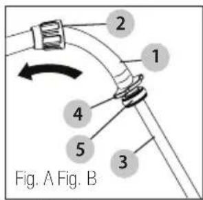
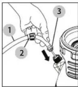
Assemble Hose to Tank
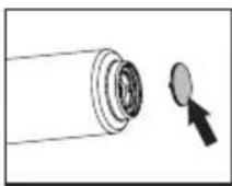
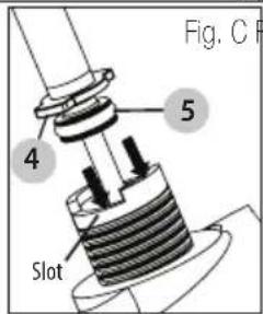
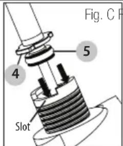
- On the hose (1), ensure the nut (2) is pulled back away from the dip tube (3) (Fig. A) to expose the hose barb adapter (4) and o-ring (5).
- Insert the dip tube (3) into the tank, (Fig. B) until the hose barb adapter (4) reaches the tank. If these tabs are not properly aligned, the hose barb adapter (4) will not insert fully into the tank, and an air leak will result.
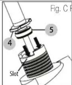
- Push the hose barb adapter (4) into the tank (Fig. C) until it stops, so the o-ring (5) seals inside to tank connection.
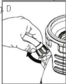
- Slide the nut (2) down over the hose barb adapter (4). Push down on the nut (2) and turn clockwise by hand until the nut (2) tightens to the tank (Fig. D). Do not use tools to over-tighten the nut (2).
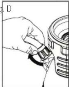
natural_image
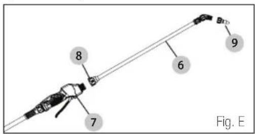
Hand holding a small object with a curved arrow indicating rotation (no text or symbols visible)Assemble Wand, Shut-Off & Nozzle
-
Install the wand (6) onto the shut-off assembly (7) and tighten the nut (8) securely.
-
Install selected nozzle (9) onto the end of the wand (6) and tighten securely.
Install the Nozzle
Select using nozzle chart.
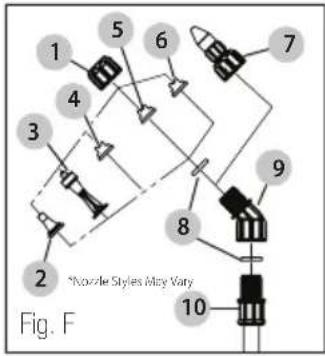
1 Cap Nut
2 Jet Stream Nozzle
3 Foaming Nozzle
4 Brown Max-Volume Fan Nozzle
5 Red High-Volume Fan Nozzle
6 Yellow Low-Volume Fan Nozzle
7 Adjustable Cone Nozzle
8 Flat Seal
9 Adapter
10 Wand
OPERATING INSTRUCTIONS
WARNING: RISK OF PERSONAL INJURY DUE TO ON VICAL EXPOSURE. Use the appropriate Personal Protective Equipment (PPE) as recommended by the chemical manufacturer and/or refer to the chemical Safety Data Sheet (SDS) of the chemical being used. This includes at least goggles, gloves, and protective clothing.
Filling
DANGER: RISK OF DEATH, SEVERE PERSONAL
INDUSTRY AND/OR PROPERTY DAMAGE FROM IMPROPER CHEMICAL USE OR MIXTURE.
- Never use flammable or combustible chemicals in this sprayer. Spraying flammable or combustible chemicals can create combustible fumes that could be ignited, causing an explosion.
- Use only chemicals indicated for spraying applications. Some chemicals may create a toxic or other hazardous atmosphere when sprayed.
-
Always refer to chemical manufacturer's instructions and/or the chemical Safety Data Sheet (SDS) for proper mixture and safe application.
-
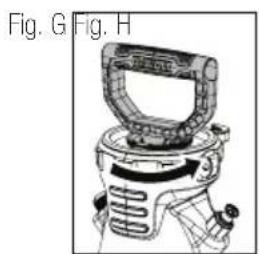
Turn the pump handle counterclockwise to remove the pump. (Fig. G)
- Fill the tank to the desired level. See fill markings on side of tank. (Always refer to chemical manufacturer for proper mixture).
- Install the pump into the tank opening and turn clockwise until tightly sealed against the tank. (Fig. H)
natural_image
Technical illustration of a mechanical device with no visible text or symbols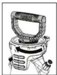
natural_image
Technical line drawing of a mechanical device with no visible text or symbolsPressurizing
WARNING: RISK OF PERSONAL INJURY AND/OR PROPERTY DAMAGE DUE TO UNINTENDED SPRAYING OF CHEMICAL. Ensure the shutoff is in the closed position (trigger released) before starting to pressurize the sprayer. The sprayer will spray when pressurizing, if the shutoff is open (trigger depressed).
NOTICE: RISK OF PROPERTY DAMAGE. Only spray with the air is calm (no wind or air movement) to prevent chemical spray from drifting onto non-targeted surfaces.
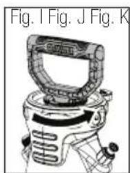
- Make sure shut-off lock is not engaged. (If shut-off lock is engaged while pressurizing, the unit will immediately start spraying).
- Push down on the handle and turn counterclockwise to unlock the handle. (Fig. I)
- Pressurize the sprayer by pumping the handle in a smooth up and down motion. (Fig. J)
- Push down on the handle and turn clockwise to lock the handle into the pump. (Fig. K)
natural_image
Line drawing of a mechanical device with no visible text or symbols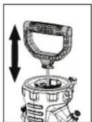
natural_image
Illustration of a mechanical device with a handle and internal components, showing a vertical double-headed arrow (no text or symbols)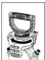
natural_image
Technical line drawing of a mechanical device with no visible text or symbolsSpraying and Locking
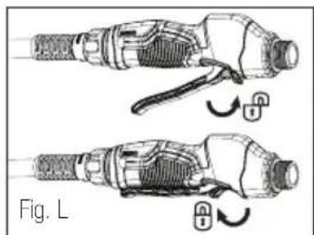
- Direct nozzle away from you and squeeze shut-off lever to begin spraying.
- For continuous spraying, squeeze lever and rotate lock. (Fig. L)
- Unlock if needed and release shut-off lever to stop spraying.
- Turn the nozzle tip to adjust the spray pattern.
natural_image
Illustration of two mechanical components with lock icons, no text or symbols present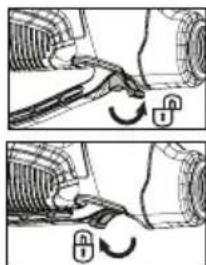
natural_image
Mechanical diagram showing two steps of a valve mechanism with no text or symbolsRelease Tank Pressure
- Pull up on the knob of the PRV until all pressure is released from the tank.
natural_image
Technical line drawing of a mechanical device with directional arrows indicating movement (no text or symbols)Finish
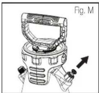
- Depressurize the tank as described in Release Tank Pressure section.
- Turn the pump handle counterclockwise to remove the pump.
ENGLISH
- Empty any remaining liquid according to the product disposal directions.
- Follow the Cleaning instructions.
Cleaning Instructions
WARNING: RISK OF PERSONAL INJURY DUE TO CHEMICAL EXPOSURE. Use the appropriate Personal Protective Equipment (PPE) as recommended by the chemical manufacturer and/or refer to the chemical Safety Dada Sheet (SDS) of the chemical being used. This includes at least goggles, gloves, and protective clothing.
- Remove the pump as described in the Finish section.
- Remove all unused chemicals from the tank.
- Store or dispose of any unused chemicals as instructed by the chemical manufacturer due to the potential for environmental damage from a spill or leak, and/or refer to disposal criteria referenced in the Safety Data Sheet (SDS).
- Fill the tank with cool, clean tap water. Replace the pump and tighten securely.
- Agitate the tank to rinse the chemical from the tank wall and pump.
- Remove the pump and empty the contents into gravel or bare soil where any trace amounts of chemical will have no effect.
- Refill the tank with cool, clean tap water.
- Make sure the pump is free of dirt or debris and reinstall into the tank. Tighten securely.
- Pressurize the tank as described in the Pressurizing section.
- Direct the nozzle away from you in a safe direction, where any remaining chemical in the hose will have no effect, and activate the shut-off for at least 30 seconds to clean the hose and shut-off.
- Release pressure as described in the Release Tank Pressure section.
- Remove the pump and empty the contents into gravel or bare soil where any trace amounts of chemical will have no effect.
- Repeat steps 7 - 12 until thoroughly cleaned.
Sprayer Storage
- Sprayer tank should be hung upside down, with the pump removed.
- Do not store or leave any solution in the tank after use.
- Store in a warm, dry location out of direct sunlight.
- Keep the sprayer and all chemicals out of the reach of children
MAINTENANCE INSTRUCTIONS
WARNING: RISK OF PERSONAL INJURY AND/OR PROPERTY DAMAGE DUE TO CHEMICAL EXPOSURE.
Always ensure that all chemical has been removed from the sprayer and the sprayer has been cleaned prior to performing any maintenance.
WARNING: RISK OF PERSONAL INJURY. Always reduce pressure from the sprayer prior to performing any maintenance. Disassembly of a sprayer that is still pressurized may result in the high speed ejection of components.
Pump Lubrication
At least once per season the o-rings in the pump should be cleaned and lubricated using petroleum jelly. Heavy use may require more frequent cleaning and lubrication.
Pump Disassembly & Reassembly
NOTICE: Remove pump from tank prior to d assembly.
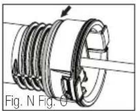
- Inspect gasket. If worn or damaged, remove and replace. (Fig. N)
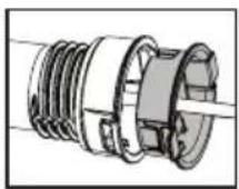
- To remove pump cap from pump barrel, squeeze the tabs on the cap and pull away from barrel. (Fig. O)
natural_image
Mechanical assembly diagram showing a threaded component with internal gears and a shaft (no text or symbols)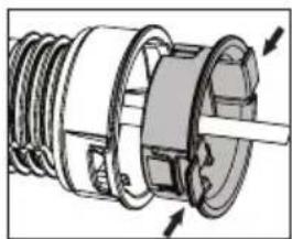
natural_image
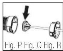
Cross-sectional diagram of a mechanical assembly with no visible text or symbols- Inspect o-ring. If worn or damaged, remove and replace. Lubricate o-ring with petroleum jelly. (Fig. P)
- Inspect check valve in bottom of barrel. If worn or damaged, remove and replace by pressing into hole in bottom of barrel. (Fig. Q)
- Insert the pump handle assembly into the barrel. Align the tabs of the pump cap with the rectangle cutouts on the barrel. Push cap into place until the cap snaps securely into position. (Fig. R)
Nozzle Maintenance
- If nozzle clogs, remove and disassemble the nozzle assembly.
- Clean the openings of any obstructions and reassemble.
Shut-off Maintenance
NOTICE: Always depressurize sprayer before maintenance by activating shut-off and spraying contents out.
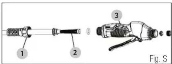
- Unscrew the hose nut (1) from the shut-off assembly (3).
- Remove the hose with attached filter (2) from the shut-off assembly (3).
- Clean any debris from inside the shut-off assembly (3), or the filter (2) by rinsing with cool, clean water.
- Reassemble the components as shown and tighten all connections securely.
TROUBLESHOOTING
| PROBLEM CAUSE SOLUTION | ||
| Sprayer starts to spray when pumping or sprayer will not stop spraying when shut-off handle is released. | Shut-off lock is engaged. Squeeze shut-off handle and disengage the lock. | |
| Sprayer leaks at pump or sprayer does not build pressure. | 1. Dirt or debris on pump gasket or closure.2. Chipped, torn, swollen or defective pump gasket.3. Check valve at bottom of pump assembly.4. Inspect o-ring on piston.5. Loose hose. | 1. Clean dirt or debris from gasket or closure.2. Remove old gasket and replace with new.3. Replace if missing or damaged.4. Lubricate the pump as described in Maintenance section.5. Re-insert hose barb adapter, then tighten hose nut. |
| Sprayer material overflows through pump barrel or pump handle rises when handle is unlocked. | 1. Dirt or debris under check valve on pump.2. Chipped, torn or swollen pump check valve. | 1. Clean check valve and valve sealing surface on pump.2. Replace check valve. |
| Hose leaks at tank. 1. Loose hose. | 2. Cracked, swollen or faulty hose. | 1. Re-insert hose barb adapter, then tighten hose nut.2. Replace shut-off assembly. |
| Hose leaks at shut-off. Swollen, slit or faulty hose. Replace shut-off assembly. | ||
| Sprayer is difficult to pump. 1. Damaged | piston o-ring.2. Piston o-ring is dry. | 1. Replace piston o-ring.2. Lubricate the pump as described in Maintenance section. |
| Nozzle drips when shut-off handle is released. | Dirt or debris in shut-off valve. 1. Replace shut-off assembly.2. See Shut-off Maintenance section. | |
| Sprayer tank leaks. Evidence of spray material escaping from the tank. | Replace entire sprayer. | |
| Nozzle tip leaks, poor spray pattern, partial spray or complete stoppage. | 1. Nozzle seal is missing or damaged.2. Spray wand or nozzle clogged.3. Shut-off filter clogged. | 1. Replace nozzle seal at end of wand.2. Remove and clean the wand and nozzle.3. Remove shut-off hose and clean the filter. |
Three Year Limited Warranty
The warranty of this product is covered by: The Fountainhead Group, Inc. (800)-311-9903
We warrant that each product sold by us will be free from defects in material and workmanship for a period of three years from the date of shipment by us. We make no other express warranties, and all implied warranties, including fitness and merchantability, are limited to three years from the date of shipment by us. Within the warranty period, we will repair or replace any part found to be defective upon our examination but will not pay shipping cost or other expenses. To obtain warranty service, contact us at: The Fountainhead Group, Inc., c/o Customer Service, 23 Garden Street, New York Mills, New York 13417, or call prepaid, Area Code (800) 311-9903 or (315) 736-0037. Merchandise may not be returned without prior permission and must be returned to us prepaid. This warranty service is an exclusive remedy and we are not responsible for any consequential or incidental damages or injury to person(s) or property. This warranty shall not apply to any product which has been subject to misuse, negligence or accident, or been damaged in shipment, or misapplied, or which has been modified or repaired by unauthorized persons. This warranty only applies to products owned by persons purchasing directly from us or from our approved distributors and merchandisers. The right is reserved to incorporate subsequent design or parts changes after publication and without reissue of descriptive literature or catalogs.
NOTE: Limitations on duration of implied warranty and/or consequential damages might not apply to you if your state does not permit them. This warranty gives you specific legal rights in addition to rights you may have under state law..
© 2020 DEWALT
DEWALT® and GUARANTEED TOUGH® are registered trademarks of the DEWALT Industrial Tool Co., used under license. All rights reserved. The yellow and black color scheme is a trademark for DEWALT Power Tools and Accessories.
Manufactured under license by:
The Fountainhead Group, Inc. 23 Garden Street
New York Mills, NY 13417 U.S.A.
Fax: (315) 768-4220
Email: Info@TheFGI.com
www.TheFountainheadGroup.com
THIS PAGE INTENTIONALLY LEFT BLANK ESTA PÁGINA SE HA DEJADO EN BLANCO INTENCIONALMENTE CETTE PAGE A INTENTIONNELLEMENT ÉTÉ LAISSÉE EN BLANC
natural_image
Hand holding a belt switch inside a mechanical component (no text or symbols visible)natural_image
Technical line drawing of a mechanical device with no visible text or symbols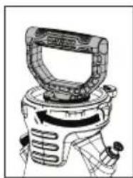
natural_image
Technical line drawing of a mechanical device with no visible text or symbolsPresurización
natural_image
Mechanical device with a lever and shaft, showing upward motion (no text or symbols)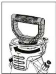
natural_image
Line drawing of a mechanical device with a handle and control knob (no text or symbols)Atomizador y seguro
natural_image
Technical illustration of two mechanical components with lock indicators, shown in side-by-side assembly (no text or symbols)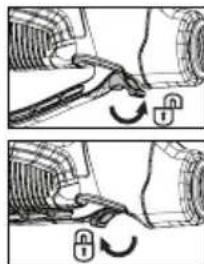
natural_image
Mechanical diagram showing two steps of a tool interacting with a vehicle (no text or symbols present)natural_image
Technical line drawing of a mechanical device with directional arrows indicating motion (no text or symbols)Terminar
natural_image
Mechanical component diagram showing threaded shaft and housing (no text or symbols)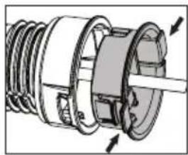
natural_image
Cross-sectional diagram of a mechanical assembly showing internal components and directional arrows (no text or labels)The Fountainhead Group, Inc. (800)-311-9903
The Fountainhead Group, Inc.
23 Garden Street
New York Mills, NY 13417 U.S.A.
Fax: (315) 768-4220
Email: Info@TheFGI.com
www.TheFountainheadGroup.com
THIS PAGE INTENTIONALLY LEFT BLANK ESTA PÁGINA SE HA DEJADO EN BLANCO INTENCIONALMENTE CETTE PAGE A INTENTIONNELLEMENT ÉTÉ LAISSÉE EN BLANC

natural_image
Hand holding a component with an arrow indicating rotation (no text or symbols)natural_image
Technical line drawing of a mechanical device with no visible text or symbolsPressurisation
natural_image
Line drawing of a mechanical device with a top component (no text or symbols)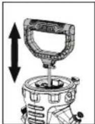
natural_image
Mechanical device with a lever and housing, showing upward and downward motion arrows (no text or symbols)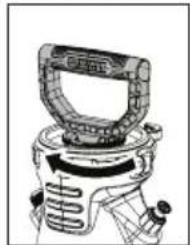
natural_image
Technical line drawing of a mechanical device with no visible text or symbolsnatural_image
Technical illustration of two mechanical components with lock and adjustment arrows, labeled Fig. L (no text or symbols on the components themselves)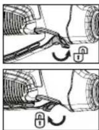
natural_image
Mechanical diagram showing two steps of a valve mechanism with no text or symbolsnatural_image
Technical line drawing of a mechanical device with no visible text or symbolsnatural_image
Technical illustration of a mechanical component with threaded shaft and flange (no text or symbols)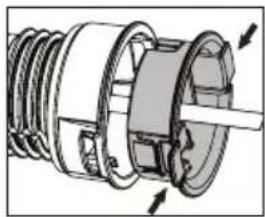
natural_image
Cross-sectional diagram of a mechanical assembly with no visible text or symbolsThe Fountainhead Group, Inc. (800)-311-9903
The Fountainhead Group, Inc.
23 Garden Street
New York Mills, NY 13417 U.S.A.
Fax: (315) 768-4220
Email: Info@TheFGI.com
www.TheFountainheadGroup.com
Manual No. 184599
Rev. A Date: 09/16/20
ECN19-155
8.5" × 5.5"