DCE300 - Crimping tool DEWALT - Free user manual and instructions
Find the device manual for free DCE300 DEWALT in PDF.

User questions about DCE300 DEWALT
0 question about this device. Answer the ones you know or ask your own.
Ask a new question about this device
Download the instructions for your Crimping tool in PDF format for free! Find your manual DCE300 - DEWALT and take your electronic device back in hand. On this page are published all the documents necessary for the use of your device. DCE300 by DEWALT.
USER MANUAL DCE300 DEWALT
20V Max* Cordless Died Cable Crimping Tool
English (original instructions) 1
Definitions: Safety Alert Symbols and Words
This instruction manual uses the following safety alert symbols and words to alert you to hazardous situations and your risk of personal injury or property damage.
DANGER: Indicates an imminently hazardous situation which, if not avoided, will result in death or serious injury.
WARNING: Indicates a potentially hazardous situation which, if not avoided, could result in death or serious injury.
CAUTION: Indicates a potentially hazardous situation which, if not avoided, may result in minor or moderate injury.
(### without word) Indicates a safety related message.
NOTICE: Indicates a practice not related to personal injury which, if not avoided, may result in property damage.
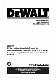
FIG. A
1 Die holder
2 Hydraulic ram
3 Shoulder strap ring
4 Reverse trigger switch
5 Trigger switch
6 Main handle
7 LED Worklight
8 Battery release button
9 Battery pack
10 Diagnostics panel
11 Power ON/OFF button
12 Micro USB port
13 Shoulder strap clip
WARNING! Read all safety warnings and all
instructions. Failure to follow the warnings and instructions may result in electric shock, fire and/or serious injury.

WARNING: To reduce the risk of injury, read the instruction manual.
English
SAVE ALL WARNINGS AND INSTRUCTIONS FOR FUTURE REFERENCE
GENERAL POWER TOOL SAFETY WARNINGS
The term "power tool" in the warnings refers to your mains-operated (corded) power tool or battery-operated (cordless) power tool.
WARNING! Read all safety warnings and all instructions. Failure to follow the warnings and instructions may result in electric shock, fire and/or serious injury.
1) Work Area Safety
a) Keep work area clean and well lit. Cluttered or dark areas invite accidents.
b) Do not operate power tools in explosive atmospheres, such as in the presence of flammable liquids, gases or dust. Power tools create sparks which may ignite the dust or fumes.
c) Keep children and bystanders away while operating a power tool. Distractions can cause you to lose control.
2) Electrical Safety
a) Power tool plugs must match the outlet. Never modify the plug in any way. Do not use any adapter plugs with earthed (grounded) power tools. Unmodified plugs and matching outlets will reduce risk of electric shock.
b) Avoid body contact with earthed or grounded surfaces such as pipes, radiators, ranges and refrigerators. There is an increased risk of electric shock if your body is earthed or grounded.
c) Do not expose power tools to rain or wet conditions. Water entering a power tool will increase the risk of electric shock.
d) Do not abuse the cord. Never use the cord for carrying, pulling or unplugging the power tool. Keep cord away from heat, oil, sharp edges or moving parts. Damaged or entangled cords increase the risk of electric shock.
e) When operating a power tool outdoors, use an extension cord suitable for outdoor use. Use of a cord suitable for outdoor use reduces the risk of electric shock.
f) If operating a power tool in a damp location is unavoidable, use a ground fault circuit interrupter (GFCI) protected supply. Use of a GFCI reduces the risk of electric shock.
3) Personal Safety
a) Stay alert, watch what you are doing and use common sense when operating a power tool. Do not use a power tool while you are tired or under the influence of drugs, alcohol or medication. A moment of inattention while operating power tools may result in serious personal injury.
b) Use personal protective equipment. Always wear eye protection. Protective equipment such as dust mask, non-skid safety shoes, hard hat, or hearing
protection used for appropriate conditions will reduce personal injuries.
c) Prevent unintentional starting. Ensure the switch is in the off position before connecting to power source and/or battery pack, picking up or carrying the tool. Carrying power tools with your finger on the switch or energizing power tools that have the switch on invites accidents.
d) Remove any adjusting key or wrench before turning the power tool on. A wrench or a key left attached to a rotating part of the power tool may result in personal injury.
e) Do not overreach. Keep proper footing and balance at all times. This enables better control of the power tool in unexpected situations.
f) Dress properly. Do not wear loose clothing or jewelry. Keep your hair, clothing and gloves away from moving parts. Loose clothes, jewelry or long hair can be caught in moving parts.
g) If devices are provided for the connection of dust extraction and collection facilities, ensure these are connected and properly used. Use of dust collection can reduce dust-related hazards.
h) Do not let familiarity gained from frequent use of tools allow you to become complacent and ignore tool safety principles. A careless action can cause severe injury within a fraction of a second.
4) Power Tool Use and Care
a) Do not force the power tool. Use the correct power tool for your application. The correct power tool will do the job better and safer at the rate for which it was designed.
b) Do not use the power tool if the switch does not turn it on and off. Any power tool that cannot be controlled with the switch is dangerous and must be repaired.
c) Disconnect the plug from the power source and/or the battery pack from the power tool before making any adjustments, changing accessories, or storing power tools. Such preventive safety measures reduce the risk of starting the power tool accidentally.
d) Store idle power tools out of the reach of children and do not allow persons unfamiliar with the power tool or these instructions to operate the power tool. Power tools are dangerous in the hands of untrained users.
e) Maintain power tools. Check for misalignment or binding of moving parts, breakage of parts and any other condition that may affect the power tool's operation. If damaged, have the power tool repaired before use. Many accidents are caused by poorly maintained power tools.
f) Keep cutting tools sharp and clean. Properly maintained cutting tools with sharp cutting edges are less likely to bind and are easier to control.
g) Use the power tool, accessories and tool bits, etc. in accordance with these instructions, taking into account the working conditions and the work to be performed. Use of the power tool for
ENGLISH
operations different from those intended could result in a hazardous situation.
h) Keep handles and grasping surfaces dry, clean and free from oil and grease. Slippery handles and grasping surfaces do not allow for safe handling and control of the tool in unexpected situations.
5) Battery Tool Use and Care
a) Recharge only with the charger specified by the manufacturer. A charger that is suitable for one type of battery pack may create a risk of fire when used with another battery pack.
b) Use power tools only with specifically designated battery packs. Use of any other battery packs may create a risk of injury and fire.
c) When battery pack is not in use, keep it away from other metal objects, like paper clips, coins, keys, nails, screws, or other small metal objects, that can make a connection from one terminal to another. Shorting the battery terminals together may cause burns or a fire.
d) Under abusive conditions, liquid may be ejected from the battery; avoid contact. If contact accidentally occurs, flush with water. If liquid contacts eyes, additionally seek medical help. Liquid ejected from the battery may cause irritation or burns.
e) Do not use a battery pack or tool that is damaged or modified. Damaged or modified batteries may exhibit unpredictable behaviour resulting in fire, explosion or risk of injury.
f) Do not expose a battery pack or tool to fire or excessive temperature. Exposure to fire or temperature above 265 °F (130 °C) may cause explosion.
9) Follow all charging instructions and do not charge the battery pack or tool outside the temperature range specified in the instructions. Charging improperly or at temperatures outside the specified range may damage the battery and increase the risk of fire.
6) Service
a) Have your power tool serviced by a qualified repair person using only identical replacement parts. This will ensure that the safety of the power tool is maintained.
b) Never service damaged battery packs. Service of battery packs should only be performed by the manufacturer or authorized service providers.
Additional Safety Rules for Crimping Tool
DRINGER: Use only approved connectors, cables and cables in manufacturer-approved combinations for successful installation. Combining materials not approved by manufacturers can result in faulty installations. Faulty installations can result in catastrophic failures, injury to installers and damage to property.
DANGER: To reduce the risk of serious injury, turn-off power to the electrical lines before
making a crimp. Failure to shut off power prior to work could result in severe injury or death and property damage.
WARNING: Use the crimping tool only with PMLT-approved dies. Other uses or modifying the crimping tool for other applications may damage the crimping tool, damage the dies and/or cause personal injury or create defective connections.
WARNING: Though this DEWALT crimping tool will reach the proper pressure to complete a crimp successfully, connections can only be effective when the connection is free from defects and when the crimp is properly prepared according to the connector manufacturer's installation procedures. Proper preparation and installation is the responsibility of the installing contractor.
- Keep all body parts away from the hydraulic ram and dies during operation and any time the power is ON. A moment of inattention while operating power tools, may result in serious personal injury. Fingers or hands can be crushed, fractured or amputated if they become caught in the dies or moving parts.
- Inspect tool and dies before use. Never attempt to repair a damaged crimping tool head or dies. A die that has been modified in any way can crack during crimping resulting in serious injury. Discard the entire damaged die. Replacement or repair of tool head may be required.
- This tool produces large forces that can break dies or parts and cause injury. Always be attentive and take proper safety precautions, including wearing eye protection.
- Crush hazard. Never run the tool without appropriate dies installed.
- Only trained personnel should operate this tool.
- Before operating, inspect the tool and LEDs on the diagnostics panel. Correct any problems before using the tool. Reference the Troubleshooting section for a list of possible problems and solutions.
- Before operating the DEWALT DCE300 crimping tool, read and understand all safety and operating instructions including the connector manufacturer's installation instructions and the instructions for any other equipment used with this tool. Failure to follow all instructions and warnings may result in property damage and/or serious personal injury.
- Keep the crimping area of the tool free from hands and other objects while tool is in use. Fingers could be crushed.
- Secure and support the material prior to making the crimp to prevent movement during crimping.
- Follow connector manufacturer's installation instructions. Other uses may cause damage to the tool, accessories, and workpiece.
- Keep a firm grip on the tool at all times. Forces on the tool may change during and after the crimp.
English
- Always wear eye protection. Crimp operations may cause material pieces to fly. Flying particles can cause permanent eye damage.
• Always wear gloves when operating tool and handling materials. The ends of the materials can be sharp and can cause serious personal injury.
• Always wear safety shoes to protect your feet from sharp metal debris on the floor.
Additional Safety Information
WARNING: ALWAYS use safety glasses. Everyday eyeglasses are NOT safety glasses. Also use face or dust mask if cutting operation is dusty. ALWAYS WEAR CERTIFIED SAFETY EQUIPMENT:
• ANSI Z87.1 eye protection (CAN/CSA Z94.3),
• ANSI S12.6 (S3.19) hearing protection,
• NIOSH/OSHA/MSHA respiratory protection.
WARNING: Some dust created by power sanding, sanding, grinding, drilling, and other construction activities contains chemicals known to the State of California to cause cancer, birth defects or other reproductive harm. Some examples of these chemicals are:
- lead from lead-based paints,
• crystalline silica from bricks and cement and other masonry products, and
• arsenic and chromium from chemically-treated lumber.
Your risk from these exposures varies, depending on how often you do this type of work. To reduce your exposure to these chemicals: work in a well ventilated area, and work with approved safety equipment, such as those dust masks that are specially designed to filter out microscopic particles.
- Avoid prolonged contact with dust from power sanding, sawing, grinding, drilling, and other construction activities. Wear protective clothing and wash exposed areas with soap and water. Allowing dust to get into your mouth, eyes, or lay on the skin may promote absorption of harmful chemicals.
WARNING: Use of this tool can generate and/or disperse dust, which may cause serious and permanent respiratory or other injury. Always use NIOSH/OSHA approved respiratory protection appropriate for the dust exposure. Direct particles away from face and body.
WARNING: Always wear proper personal hearing protection that conforms to ANSI S12.6 (S3.19)
during use. Under some conditions and duration of use, noise from this product may contribute to hearing loss.
CAUTION: When not in use, place tool on its side can be stable surface where it will not cause a
tripping or falling hazard. Some tools with large battery packs will stand upright on the battery pack but may be easily knocked over.
• Air vents often cover moving parts and should be avoided. Loose clothes, jewelry or long hair can be caught in moving parts.
The label on your tool may include the following symbols. The symbols and their definitions are as follows:
V....volts
Hz hertz
min......minutes
= - = or DC.....direct current
Class I Construction (grounded)
.../min.....per minute
BPM.....beats per minute
IPM ____ impacts per minute
RPM......revolutionsper minute
sfpm .... surface feet per minute
SPM ...... strokes per minute
A......amperes
W.....watts
\~ or AC......alternating current
or AC/DC....alternating or direct current
ClassII
Construction
(double insulated)
n_0 no load speed
n ......rated speed
⊕ ....earthing terminal
⚠️ ......safety alert symbol
▲......visible radiation
......wearrespiratory protection
weareye protectic
O....wearhearing protection
electricshock hazard
crush hazard
readall documentation
BATTERIES AND CHARGERS
The battery pack is not fully charged out of the carton. Before using the battery pack and charger, read the safety instructions below and then follow charging procedures outlined. When ordering replacement battery packs, be sure to include the catalog number and voltage. Your tool uses a DEWALT charger. Be sure to read all safety instructions before using your charger. Consult the chart at the end of this manual for compatibility of chargers and battery packs.
READ ALL INSTRUCTIONS
Important Safety Instructions for All Battery Packs
WARNING: Read all safety warnings and all instructions for the battery pack, charger and power tool. Failure to follow the warnings and instructions may result in electric shock, fire and/or serious injury.
- Do not charge or use the battery pack in explosive atmospheres, such as in the presence of flammable liquids, gases or dust. Inserting or removing the battery pack from the charger may ignite the dust or fumes.
- NEVER force the battery pack into the charger. DO NOT modify the battery pack in any way to fit into a non-compatible charger as battery pack may rupture causing serious personal injury. Consult the chart at the end of this manual for compatibility of batteries and chargers.
- Charge the battery packs only in designated DeWALT chargers.
• DO NOT splash or immerse in water or other liquids.
- Do not store or use the tool and battery pack in locations where the temperature may reach or exceed 104 °F (40 °C) (such as outside sheds or metal buildings in summer). For best life store battery packs in a cool, dry location.
NOTE: Do not store the battery packs in a tool with the trigger switch locked on. Never tape the trigger switch in the ON position.
- Do not incinerate the battery pack even if it is severely damaged or is completely worn out. The battery pack can explode in a fire. Toxic fumes and materials are created when lithium ion battery packs are burned.
- If battery contents come into contact with the skin, immediately wash area with mild soap and water. If battery liquid gets into the eye, rinse water over the open eye for 15 minutes or until irritation ceases. If medical attention is needed, the battery electrolyte is composed of a mixture of liquid organic carbonates and lithium salts.
- Contents of opened battery cells may cause respiratory irritation. Provide fresh air. If symptoms persist, seek medical attention.
WARNING: Burn hazard. Battery liquid may be flammable if exposed to spark or flame.
WARNING: Fire hazard. Never attempt to open the battery pack for any reason. If the battery pack case is cracked or damaged, do not insert into the charger. Do not crush, drop or damage the battery pack. Do not use a battery pack or charger that has received a sharp blow, been dropped, run over or damaged in any way (e.g., pierced with a nail, hit with a hammer, stepped on). Damaged battery packs should be returned to the service center for recycling.
Transportation
WARNING: Fire hazard. Do not store or carry the battery pack so that metal objects can contact exposed battery terminals. For example, do not place the battery pack in aprons, pockets, tool boxes, product kit boxes, drawers, etc., with loose nails, screws, keys, etc. Transporting batteries can possibly cause fires if the battery terminals inadvertently come in contact with conductive materials such as keys, coins, hand tools and the like. The US Department of Transportation Hazardous Material Regulations (HMR) actually prohibit transporting batteries in commerce or on airplanes in carry-on baggage UNLESS they are properly protected from short circuits. So when transporting individual battery packs, make sure that the battery terminals are protected and well insulated from materials that could contact them and cause a short circuit.
Shipping the DeWALT FLEXVOLT™ Battery
The DEWALT FLEXVOLT™ battery has two modes: Use and Shipping.
Use Mode: When the FLEXVOLT™ battery stands alone or is in a DEWALT 20V Max* product, it will operate as a 20V Max* battery. When the FLEXVOLT™ battery is in a 60V Max* or a 120V Max* (two 60V Max* batteries) product, it will operate as a 60V Max* battery.
Shipping Mode: When the cap is attached to the FLEXVOLT™ battery, the battery is in Shipping Mode. Strings of cells are
electrically disconnected within the pack resulting in three batteries with a lower Watt hour (Wh) rating as compared to one battery with a higher Watt hour rating. This increased quantity of three batteries with the lower Watt hour rating can exempt the pack from certain shipping regulations that are imposed upon the higher Watt hour batteries.
The battery label indicates two Watt hour ratings (see example). Depending on how the battery is shipped, the appropriate Watt hour rating must be used to determine the applicable shipping requirements. If utilizing the shipping cap, the pack will be considered 3 batteries at the Watt hour rating indicated for "Shipping". If shipping without the cap or in a tool, the pack will be considered one battery at the Watt hour rating indicated next to "Use".
Example of Use and Shipping Label Marking
USE: 120 Wh Shipping: 3 x 40 Wh
Shipping Watt hour rating indicates 3 x 40 Wh, meaning 3 batteries of 40 Watt hours each. The Use Watt hour rating indicates 120 Watt hour (1 battery implied).
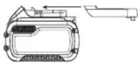
Fuel Gauge Battery Packs (Fig. B)
Some DEWALT battery packs include a fuel gauge which consists of three green LED lights that indicate the level of charge remaining in the battery pack.
The fuel gauge is an indication of approximate levels of charge remaining in the battery pack according to the following indicators:
To actuate the fuel gauge, press and hold the fuel gauge button. A combination of the three green LED lights will illuminate designating the level of charge left. When the level of charge in the battery is below the usable limit, the fuel gauge will not illuminate and the battery will need to be recharged.
FIG. B

NOTE: The fuel gauge is only an indication of the charge left on the battery pack. It does not indicate tool functionality
ENGLISH
and is subject to variation based on product components, temperature and end-user application.
For more information regarding fuel gauge battery packs, please contact call 1-800-4-DrWALT (1-800-433-9258) or visit our website www.dewalt.com.
The RBRC® Seal
The RBRC® (Rechargeable Battery
Recycling Corporation) Seal on the nickel cadmium, nickel metal hydride or lithium-ion batteries (or battery packs) indicates that the costs to recycle these batteries (or battery packs) at the end of their useful

life have already been paid by DEWALT. In some areas, it is illegal to place spent nickel cadmium, nickel metal hydride or lithium-ion batteries in the trash or municipal solid waste stream and the Call 2 Recycle® program provides an environmentally conscious alternative.
Call 2 Recycle, Inc., in cooperation with DeWALT and other battery users, has established the program in the United States and Canada to facilitate the collection of spent nickel cadmium, nickel metal hydride or lithium-ion batteries. Help protect our environment and conserve natural resources by returning the spent nickel cadmium, nickel metal hydride or lithium-ion batteries to an authorized DeWALT service center or to your local retailer for recycling. You may also contact your local recycling center for information on where to drop off the spent battery. RBRC® is a registered trademark of Call 2 Recycle, Inc.
RBRC™ is a registered trademark of the Rechargeable Battery Recycling Corporation.
Important Safety Instructions for All Battery Chargers
WARNING: Read all safety warnings and all instructions for the battery pack, charger and power tool. Failure to follow the warnings and instructions may result in electric shock, fire and/or serious injury.
- DO NOT attempt to charge the battery pack with any chargers other than the ones in this manual.
The charger and battery pack are specifically designed to work together.
• These chargers are not intended for any uses other than charging DEWALT rechargeable batteries.
Any other uses may result in risk of fire, electric shock or electrocution.
- Do not expose the charger to rain or snow.
- Pull by the plug rather than the cord when disconnecting the charger. This will reduce the risk of damage to the electric plug and cord.
- Make sure that the cord is located so that it will not be stepped on, tripped over or otherwise subjected to damage or stress.
- Do not use an extension cord unless it is absolutely necessary. Use of improper extension cord could result in risk of fire, electric shock or electrocution.
- When operating a charger outdoors, always provide a dry location and use an extension cord suitable
for outdoor use. Use of a cord suitable for outdoor use reduces the risk of electric shock.
- An extension cord must have adequate wire size (AWG or American Wire Gauge) for safety. The smaller the gauge number of the wire, the greater the capacity of the cable, that is, 16 gauge has more capacity than 18 gauge. An undersized cord will cause a drop in line voltage resulting in loss of power and overheating. When using more than one extension to make up the total length, be sure each individual extension contains at least the minimum wire size. The following table shows the correct size to use depending on cord length and nameplate ampere rating. If in doubt, use the next heavier gauge. The lower the gauge number, the heavier the cord.
Minimum Gauge for Cord Sets
| Volts | Total Length of Cord in Feet (meters) | ||||
| 120 V 25 (7.6) | 50 (15.2) 100 (30.5) 150 (45.7) | ||||
| 240 V 50 (15.2) | 100 (30.5) 200 (61.0) 300 (91.4) | ||||
| Ampere Rating | American Wire Gauge | ||||
| More Than | Not More Than | ||||
| 0 6 18 | 16 16 14 | ||||
| 6 10 18 | 16 14 12 | ||||
| 10 12 | 16 16 14 12 | ||||
| 12 16 | 14 12 Not Recommended | ||||
- Do not place any object on top of the charger or place the charger on a soft surface that might block the ventilation slots and result in excessive internal heat. Place the charger in a position away from any heat source. The charger is ventilated through slots in the top and the bottom of the housing.
- Do not operate the charger with a damaged cord or plug.
- Do not operate the charger if it has received a sharp blow, been dropped or otherwise damaged in any way. Take it to an authorized service center.
- Do not disassemble the charger; take it to an authorized service center when service or repair is required. Incorrect reassembly may result in a risk of electric shock, electrocution or fire.
- Disconnect the charger from the outlet before attempting any cleaning. This will reduce the risk of electric shock. Removing the battery pack will not reduce this risk.
• NEVER attempt to connect 2 chargers together.
- The charger is designed to operate on standard 120V household electrical power. Do not attempt to use it on any other voltage. This does not apply to the vehicular charger.
WARNING: Shock hazard. Do not allow any liquid to go inside the charger. Electric shock may result.
WARNING: Burn hazard. Do not submerge the battery pack in any liquid or allow any liquid to enter the battery pack. Never attempt to open the battery pack for any reason. If the plastic housing of the battery pack breaks or cracks, return to a service center for recycling.
CAUTION: Burn hazard. To reduce the risk of injury, discharge only DEWALT rechargeable battery packs.
Other types of batteries may overheat and burst resulting in personal injury and property damage.
NOTICE: Under certain conditions, with the charger plugged into the power supply, the charger can be shorted by foreign material. Foreign materials of a conductive nature, such as, but not limited to, grinding dust, metal chips, steel wool, aluminum foil or any buildup of metallic particles should be kept away from the charger cavities. Always unplug the charger from the power supply when there is no battery pack in the cavity. Unplug the charger before attempting to clean.
Charging a Battery (Fig. C)
- Plug the charger into an appropriate outlet before inserting battery pack.
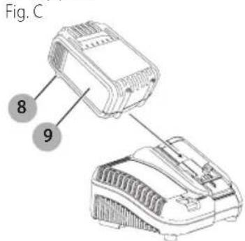
- Insert the battery pack 9 into the charger, making sure the battery pack is fully seated in the charger. The red (charging) light will blink continuously indicating that the charging process has started.
- The completion of charge will be indicated by the red light remaining ON continuously. The battery pack is fully charged and may be used at this time or left in the charger. To remove the battery pack from the charger, push the battery release button 8 on the battery pack.
NOTE: To ensure maximum performance and life of lithium-ion battery packs, charge the battery pack fully before first use.
Charger Operation
Refer to the indicators below for the charge status of the battery pack.
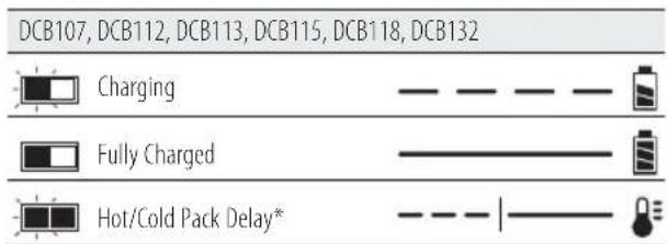
* DCB107, DCB112, DCB113, DCB115, DCB118, DCB132:
The red light will continue to blink, but a yellow indicator light will be illuminated during this operation. Once the battery pack has reached an appropriate temperature, the yellow light will turn off and the charger will resume the charging procedure.
The compatible charger(s) will not charge a faulty battery pack. The charger will indicate faulty battery pack by refusing to light or by displaying a problem pack or charger blink pattern.
NOTE: This could also mean a problem with a charger. If the charger indicates a problem, take the charger and battery pack to be tested at an authorized service center.
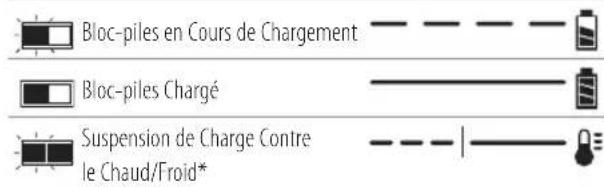
Hot/Cold Pack Delay
When the charger detects a battery pack that is too hot or too cold, it automatically starts a Hot/Cold Pack Delay, suspending charging until the battery pack has reached an appropriate temperature. The charger then automatically switches to the pack charging mode. This feature ensures maximum battery pack life.
A cold battery pack will charge at a slower rate than a warm battery pack. The battery pack will charge at that slower rate throughout the entire charging cycle and will not return to maximum charge rate even if the battery pack warms.
The DCB118 charger is equipped with an internal fan designed to cool the battery pack. The fan will turn on automatically when the battery pack needs to be cooled.
Never operate the charger if the fan does not operate properly or if ventilation slots are blocked. Do not permit foreign objects to enter the interior of the charger.
Electronic Protection System
Li-Ion tools are designed with an Electronic Protection System that will protect the battery pack against overloading, overheating or deep discharge.
The tool will automatically turn off if the Electronic Protection System engages. If this occurs, place the lithium-ion battery pack on the charger until it is fully charged.
Wall Mounting
DCB107, DCB112, DCB113, DCB115, DCB118, DCB132
These chargers are designed to be wall mountable or to sit upright on a table or work surface. If wall mounting, locate the charger within reach of an electrical outlet, and away from a corner or other obstructions which may impede air flow. Use the back of the charger as a template for the location of the mounting screws on the wall. Mount the charger securely using drywall screws (purchased separately) at least 1" (25.4 mm) long, with a screw head diameter of 0.28–0.35" (7–9 mm), screwed into wood to an optimal depth leaving approximately 7/32" (5.5 mm) of the screw exposed. Align the slots on the back of the charger with the exposed screws and fully engage them in the slots.
Charger Cleaning Instructions
WARNING: Shock hazard. Disconnect the charger for the AC outlet before cleaning. Dirt and grease may be removed from the exterior of the charger using a cloth or soft non-metallic brush. Do not use water or any cleaning solutions.
Important Charging Notes
- Longest life and best performance can be obtained if the battery pack is charged when the air temperature is between 65 °F and 75 °F (18 ° – 24 °C). DO NOT charge
English
the battery pack in an air temperature below +40 °F (+4.5 °C), or above +104 °F (+40 °C). This is important and will prevent serious damage to the battery pack.
- The charger and battery pack may become warm to the touch while charging. This is a normal condition, and does not indicate a problem. To facilitate the cooling of the battery pack after use, avoid placing the charger or battery pack in a warm environment such as in a metal shed or an uninsulated trailer.
- If the battery pack does not charge properly:
a. Check operation of receptacle by plugging in a lamp or other appliance;
b. Check to see if receptacle is connected to a light switch which turns power off when you turn out the lights;
c. Move the charger and battery pack to a location where the surrounding air temperature is approximately 65^ F – 75^ F ( 18^ – 24^ C);
d. If charging problems persist, take the tool, battery pack and charger to your local service center.
- The battery pack should be recharged when it fails to produce sufficient power on jobs which were easily done previously. DO NOT CONTINUE to use under these conditions. Follow the charging procedure. You may also charge a partially used pack whenever you desire with no adverse effect on the battery pack.
- Foreign materials of a conductive nature such as, but not limited to, grinding dust, metal chips, steel wool, aluminum foil, or any buildup of metallic particles should be kept away from charger cavities. Always unplug the charger from the power supply when there is no battery pack in the cavity. Unplug the charger before attempting to clean.
- Do not freeze or immerse the charger in water or any other liquid.
Storage Recommendations
- The best storage place is one that is cool and dry, away from direct sunlight and excess heat or cold.
- For long storage, it is recommended to store a fully charged battery pack in a cool dry place out of the charger for optimal results.
NOTE: Battery packs should not be stored completely depleted of charge. The battery pack will need to be recharged before use.
SAVE THESE INSTRUCTIONS FOR FUTURE USE
COMPONENTS (FIG. A)
WARNING: Never modify the power tool or any part of damage or personal injury could result.
Refer to Figure A at the beginning of this manual for a complete list of components.
INTENDED USE
This Cordless Died Cable Crimping Tool is designed for professional crimping of specific electrical applications only. Only trained personnel should operate this tool.
DO nOT use under wet conditions or in presence of flammable liquids or gases.
This crimping tool is a professional power tool. DO nOT let children come into contact with the tool. Supervision is required when inexperienced operators use this tool.
Introduction
The DCE300 Cordless Died Cable Crimping Tool uses an electric motor to power a hydraulic piston pump. The pumping action forces a ram forward that forces closed a set of dies (not included). When used with appropriate crimping dies, the DCE300 is designed to mechanically crimp connectors onto cable to create a tight and permanent connection.
Trigger Switch (Fig. A)
Squeezing the trigger switch 5 advances the hydraulic ram 2, while fully releasing the trigger switch stops the advance of the hydraulic ram.
Reverse Trigger Switch (Fig. A)
Squeezing the reverse trigger switch 4 retracts the hydraulic ram which releases the crimping action.
Shoulder Strap (Fig. A)
WARNING: The shoulder strap and ring are intended for transporting the tool. They are not intended for tethering or securing the tool to a person or object during use.
WARNING: Do not transport the tool with the main power ON. Switch the main power OFF prior to transporting.
Your crimping tool comes with a shoulder strap. Hook the shoulder strap clips 13 into the shoulder strap ring 3.
LED Worklight (Fig. A)
The LED worklight 7 is located on the foot of the tool. The worklight is activated when the trigger switch is depressed. It will remain on for 2 minutes. After 1 minute, 40 seconds, the light will dim to 25% indicating that the light is going to turn off.
LED Display (Fig. D)
The LED display on the top of the crimping tool includes the power ON/OFF button 11 maintenance LED 14, cycle complete LED 15, battery state of charge LED 16, and temperature LEDs 17. Refer to the LED Indications chart for specific information.
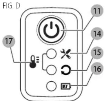
When the battery state of charge LED 16 is lit, regardless of color, the tool is ON.
DeWALT CRIMP CONNECT™ System
This crimping tool is capable of connecting with a computer via the micro USB port 12 on the back of the tool using the micro USB cable included with your tool. This allows the user to connect the DeWALT crimping tool to a computer which utilizes DEWALT's CRIMP CONNECT™ System software.
NOTE: The CRIMP CONNECT™ System software is governed by separate terms and conditions available for viewing through the software download.
Step 1: Download the CRIMP CONNECT™ System software to your computer at www.dewalt.com/crimpconnect.
Step 2: Follow the instructions in the software to create your CRIMP CONNECT™ System account.
Step 3: Connect your crimping tool with the DEWALT CRIMP CONNECT™ System software by first connecting the provided micro USB cable to the micro USB port 12 on the back of the tool to a USB port on a computer. Then go to the Home screen of the program to access tool tracking and usage reports stored on the crimping tool.
NOTE: The USB connection will not charge the tool's battery pack.
For more information on DEWALT CRIMP CONNECT™ System functionality and features, please call 1-800-4-DEWALT (1-800-433-9258), visit www.DEWALT.com or view the FAQ page and help screens located inside the software.
ASSEMBLY AND ADJUSTMENTS
WARNING: To reduce the risk of serious personal injury, turn unit off and remove the battery pack before making any adjustments or removing/installing attachments or accessories. An accidental start-up can cause injury.
WARNING: To reduce the risk of serious personal injury, do not use the crimping tool with any kind of die other than those recommended by DeWALT.
Changing the Dies (Fig. A)
WARNING: Inspect dies and connectors before use. Only use properly matched dies and connectors for the crimping head. Refer to Die Compatibility Chart for die/connector compatibility.
- Remove the battery pack.
- Clean the die holder 1 with a dry clean cloth or forced air.
- Select the appropriate size and type of crimping die for the connector and cable specified. Refer to engineering specifications and the Die Compatibility Chart.
- Slide the dies into each die holder ① until the ball detent snaps into the die groove. This locks the die into place.
- To remove the dies, first remove the battery pack, then completely open the hydraulic ram by pressing and holding the reverse trigger switch. Apply force to left or right side of the die until die slides out of die holder.
OPERATION
WARNING: To reduce the risk of serious personal injury, turn unit off and remove the battery pack before making any adjustments or removing/installing attachments or accessories. An accidental start-up can cause injury.
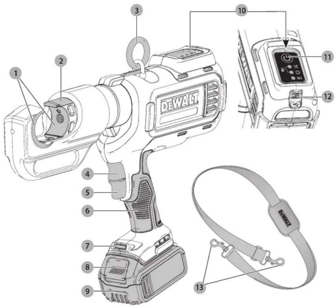
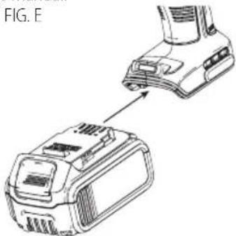
Installing and Removing the Battery Pack (Fig. E)
NOTE: For best results, make sure your battery pack is fully charged.
To install the battery pack into the tool handle, align the battery pack with the rails inside the tool's handle and slide it into the handle until the battery pack is firmly seated in the tool and ensure that it does not disengage.
To remove the battery pack from the tool, press the release button and firmly pull the battery pack out of the tool handle. Insert it into the charger as described in the charger section of this manual.
natural_image
Technical line drawing of a mechanical device with an arrow pointing to a component (no text or symbols present)Proper Hand Position (Fig. F)
WARNING: To reduce the risk of serious personal injury, A. 145 YS use proper hand position as shown.
WARNING: To reduce the risk of serious personal injury, ALWAYS hold securely in anticipation of a sudden reaction.
Proper hand position requires one hand on the main handle 6 as shown.

natural_image
Line drawing of hands operating a handheld device with a labeled component (no text or symbols present)WARNING: CUT OR AMPUTATION HAZARD. Never have any part of your body near the crimping head or moving parts during the crimp cycle, or whenever the main power is ON. Serious personal injury may occur.
WARNING: Proper material preparation and installation is the responsibility of the installing contractor.
WARNING: The crimp connectors must be used in compliance with applicable building codes
English
and as approved by the authorities having jurisdiction. For proper installation procedures and to reduce the risk of failure resulting in injury or property damage, follow all published safety and installation instructions.
Preparing the Connection
WARNING: Always follow the specific manufacturer's installation instructions for crimping tool dies being used. It is the installer's responsibility to ensure the compatibility of the cable and connectors used for the crimp. Failure to follow all instructions and warnings may result in property damage and/or serious personal injury.
- Before operating, make sure that the work area and the area below are clear of people and other distractions and that the tool and work area have been properly set up.
- Prepare the connectors and cable according to the manufacturer's specifications.
- Make sure the cable is inserted to the proper depth in the connector in accordance with the connector manufacturer's specifications.
Crimping (Fig. A, D)
WARNING: An incomplete crimp can cause property damage.
• Always use the manufacturer-approved combination of die, connector, and cable. Failure to do so, may result in an incomplete or faulty connection.
WARNING: To reduce the risk of serious personal injury, inspect the crimp head assembly for cleanliness, cracks or other damage before beginning a crimp. Using a dirty or damaged crimp head assembly could result in improper crimp connections that could lead to extensive property damage. Return damaged crimp head assembly to a DEWALT service facility.
WARNING: To reduce the risk of serious personal injury, prior to use, inspect workpieces for cracks, defects or wear. Defective workpieces may shatter.
WARNING: Before turning on the crimping tool, to save hands are clear of the crimping head.
Before beginning a crimp, check the battery pack fuel gauge to determine whether the battery charge is sufficient to complete the crimping operation.
nOTE: The tool will turn off automatically after 2 minutes of no use.
- Always follow the specific manufacturer's installation instructions for the appropriate length to strip the cable and preparation of the workpiece surface.
- Insert the entire stripped part of the cable into the connector then align the connector midway between the dies.
- Turn the tool ON by holding the power ON/OFF button 11 until all 3 LEDs illuminate green.
- Press and hold the trigger switch until the cycle is complete, indicated by the ram automatically returning
to it's original position. The LED worklight will illuminate the workpiece when the trigger is pulled.
- When the cycle is complete, the Cycle Complete LED 15 will flash green for 5 seconds. If the crimp cycle is incomplete, the cycle complete LED 15 will flash red for 5 seconds. No action is possible until the user presses the ON/OFF button.
- Repeat steps 4 and 5 according to the connector manufacturer's instructions. Crimp sequences start at the pad for lugs and the center for splices and work toward the cable.
- Complete the number of crimps specified by the manufacturer.
NOTE: If the battery dies or tool malfunctions during the cycle, the ram can retract by pressing the reverse trigger switch 4. Hold tool securely until the cylinder retracts fully.
nOTE: Clean off oxide inhibitor from the aluminum connectors after completion.
NOTE: If the tool does not complete the crimp properly, read the Troubleshooting section or take the tool to a local dealer or authorized service center.
nOTE: When crimping overhead, always confirm workpiece and tool are secure before crimping.
MAINTENANCE
WARNING: To reduce the risk of serious personal injury, turn unit off and remove the battery pack before making any adjustments or removing/installing attachments or accessories. An accidental start-up can cause injury.
WARNING: Before each use, inspect the tool (including LED indicators) and correct any problems before attempting to use.
WARNING: Skin injection hazard. The oil in the mechanism is under extreme pressure. Do not use hands to check for oil leaks.
WARNING: Explosion hazard. The internal hydraulic system creates extreme pressures. Only DEWALT-qualified personnel should service this tool.
Required Maintenance
Maintenance is required when the crimping tool reaches 15,000 cycles. Warning indicators will illuminate on the diagnostic panel 10 as follows.
- Maintenance warning at 14,500 cycles (Maintenance LED lights yellow continuously)
- Final maintenance warning at 14,900 cycles (Maintenance LED flashes yellow continuously)
- Needs service at 15,000 cycles (Maintenance LED lights red for 10 seconds then turns tool off automatically). At 15,000 cycles, the tool will no longer run. Take your tool to a local dealer or authorized service center for maintenance and recalibration.
Cleaning
WARNING: Blow dirt and dust out of all air vents with dry air at least once a week. To minimize the risk
English
of eye injury, always wear ANSI Z87.1 approved eye protection when performing this.
WARNING: Never use solvents or other harsh chemicals for cleaning the non-metallic parts of the tool. These chemicals may weaken the plastic materials used in these parts. Use a cloth dampened only with water and mild soap. Never let any liquid get inside the tool; never immerse any part of the tool into a liquid.
Regularly clean the die holder and ram head to be sure they are free of dirt and debris to ensure a proper crimp.
Accessories
WARNING: Since accessories and dies, other than the offered or recommended by DEWALT, have not been tested with this product, use of such accessories or dies with this tool could be hazardous. To reduce the risk of injury, only DEWALT-recommended accessories and dies should be used with this product.
Recommended accessories and dies for use with your tool are available at extra cost from your local dealer or authorized service center. If you need assistance in locating any accessory or die, please contact DeWALT Industrial Tool Co., 701 East Joppa Road, Towson, MD 21286, call 1-800-4-DeWALT (1-800-433-9258) or visit our website: www.dewalt.com.
Repairs
The charger and battery pack are not serviceable.
WARNING: To assure product SAFETY and REEIBILITY, repairs, maintenance and adjustment (including brush inspection and replacement) should be performed by a DeWALT factory service center or a DeWALT authorized service center. Always use identical replacement parts.
Register Online
Thank you for your purchase. Register your product now for:
- WARRAnTY sERViCE: Registering your product will help you obtain more efficient warranty service in case there is a problem with your product.
- COnFiRMATiOn OF OWnERshiP: In case of an insurance loss, such as fire, flood or theft, your registration of ownership will serve as your proof of purchase.
- FOR YOUR SAFETY: Registering your product will allow us to contact you in the unlikely event a safety notification is required under the Federal Consumer Safety Act.
Register online at www.dewalt.com/register.
Three Year Limited Warranty
DeWALT will repair, without charge, any defects due to faulty materials or workmanship for three years from the date of purchase. This warranty does not cover part failure due to normal wear or tool abuse. For further detail of warranty coverage and warranty repair information, visit www.dewalt.com or call 1-800-4-DrWALT (1-800-433-9258). This warranty does not apply to accessories or damage
caused where repairs have been made or attempted by others. This warranty gives you specific legal rights and you may have other rights which vary in certain states or provinces.
In addition to the warranty, DEWALT tools are covered by our:
1 YEAR FREE sSERVICE
DeWALT will maintain the tool and replace worn parts caused by normal use, for free, any time during the first year after purchase.
2 YEARs FREE SERVICE On DEWAIT BATTERY PACKs
DC9071, DC9091, DC9096, DC9182, DC9280, DC9360, DCB120, DCB127, DCB201, DCB203, DCB203BT, DCB207, DCB361
3 YEARs FREE sERViCE On DEWAIT BATTERY PACKs
DCB200, DCB204, DCB204BT, DCB205, DCB606
NOTE: Battery warranty voided if the battery pack is tampered with in any way. DeWALT is not responsible for any injury caused by tampering and may prosecute warranty fraud to the fullest extent permitted by law.
90 DAY MOnEY BACK gUARAnTEE
If you are not completely satisfied with the performance of your DEWALT Power Tool, Laser, or Nailer for any reason, you can return it within 90 days from the date of purchase with a receipt for a full refund – no questions asked.
IATin AMERiCA: This warranty does not apply to products sold in Latin America. For products sold in Latin America, see country specific warranty information contained in the packaging, call the local company or see website for warranty information.
FREE WARning IABEI REPIACEMENT: If your warning labels become illegible or are missing, call 1-800-4-DeWALT (1-800-433-9258) for a free replacement.
sPECiFiCATiOns
| DCE300 | |
| Battery pack 20V Max* | |
| Nominal Crimping Force 12 Tons (106kN) | |
| Operating Temperature Range 14 °F—158 °F (-10 °C—70 °C) | |
Troubleshooting Guide
BE SURE TO FOLLOW SAFETY RULES AND INSTRUCTIONS
Problem Possible Cause Possible Solution
| Tool does not turn ON when power ON/OFF switch is pressed. | Battery is not charged. Charge battery or use a new, fully charged battery. | |
| Battery is not fully inserted into tool. Remove battery and reinsert fully into the tool. | ||
| Tool does not respond when trigger switch is pressed. | Battery is too low to complete a crimp/press. Battery LED lights in red continuously. | Recharge battery in compatible DeWALT charger. |
| Other causes Refer toLED Indicationsfor additional information. | ||
| Tool is plugged into computer via micro USB cable but the maintenance LED does not light blue continuously. | Micro USB cable is not the provided cable and may only be a "charging" cable, not a "data" cable. | Use the provided data cable. |
| CRIMP CONNECTTM System software is not working properly. | Other causes View the FAQ page and help screens located inside the CRIMP CONNECTTM System software. | |
LED Indications
INDICATION USER ACTION LEDs EXAMPLE
| Unit Power | Unit ON Press ON/OFF button All 3 LEDs light in green for 1 second. |  GREEN GREEN | |
| Unit OFF Press ON/OFF button All 3 LEDs light in red for 1 second. |  RED RED | ||
| USB | Plug tool into computervia USB | Maintenance LED lights in blue continuously.nOTE: Indication is permanent as soon as tool is plugged in via USB. |  BLUE BLUE |
| Battery | Full Charge Battery LED lights in green continuously.nOTE: Indication is permanent as soon as tool is switched on. |  GREEN GREEN | |
| MediumCharge | Battery LED lights in yellow continuously.nOTE: Indication is permanent as soon as tool is switched on. |  YELLOW YELLOW | |
| Low Charge Battery LED lights in red for 10 seconds, then tool turns off automatically.nOTE: Indication is permanent as soon as tool is switched on. |  RED RED | ||
| Crimp/Press Cycle | CycleComplete | Attempt a crimp/press Cycle Complete LED flashes in green for 5 seconds. |  GREEN GREEN |
| Cycle NotComplete | Attempt a crimp/press Cycle Complete LED flashes in red for 5 seconds.nOTE: No action is possible until user presses ON/OFF button. | 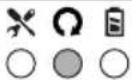 RED RED | |
| Maintenance | MaintenanceWarning | Maintenance LED lights in yellow continuously.nOTE: 500 cycles left. Indication is permanent as soon as tool is switched on. |  YELLOW YELLOW |
| FinalMaintenanceWarning | Maintenance LED flashes in yellow continuously.nOTE: 100 cycles left. Indication is permanent as soon as tool is switched on. | 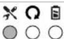 YELLOW YELLOW | |
| Needs Service Maintenance LED lights in red for 10 seconds, then tool turns off automatically.nOTE: 0 cycles left. |  RED RED | ||
| Temperature | TemperatureOut of Range | Maintenance and Cycle Complete LEDs light in red continuously.nOTE: Indication is permanent as soon as tool is switched on.LEDs turn off when acceptable temperature is reached. | 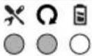 RED RED |
Die Compatibility Chart
Refer to www.DEWALT.com for latest tool/die/connector/application compatibility.
WARNING: Always follow the specific manufacturer's installation instructions for crimping tool attachments being used. It is the installer's responsibility to ensure the compatibility of the cable and connectors used for the crimp. Failure to follow all instructions and warnings may result in property damage and/or serious personal injury.
WARNING: Since accessories and dies, other than those offered or recommended by DrWALT, have not been tested with the product, use of such accessories or dies with this tool could be hazardous. To reduce the risk of injury, only DeWALT-recommended accessories and dies should be used with this product.
Recommended accessories and dies for use with your tool are available at extra cost from your local dealer or authorized service center. If you need assistance in locating any accessory or die, please contact DeWALT Industrial Tool Co., 701 East Joppa Road, Towson, MD 21286, call 1-800-4-DeWALT (1-800-433-9258) or visit our website: www.dewalt.com.
Connections made with this tool and combination of die and connector families in the chart below create cULus Classified crimps according to the UL 486A-B classification standards.
Copper Short and Long Barrel Lugs and Splices
| Die Brand | Die Catalog Number Cable | Size | Connector Color | Connector Brand Family Number of Crimps | ||
| Burndy | U8CRT | Copper #8 | Red | Burndy | YA, YA-TC, YA-L, YA-L-TC, YA-2L, YA-2LN, YA-L-2TC, YS, YS-L | 1 |
| U5CRT Copper #6 Blue | ||||||
| U4CRT Copper #4 Gray | ||||||
| U3CRT Copper #3 White 2 | ||||||
| U2CRT Copper #2 Brown | ||||||
| U1CRT Copper #1 Green | ||||||
| U25RT Copper 1/0 AWG Pink | ||||||
| U26RT Copper 2/0 AWG Black | ||||||
| U27RT Copper 3/0 AWG Orange | ||||||
| U28RT Copper 4/0 AWG Purple 1 | ||||||
| U29RT Copper 250 kcmil Yellow | ||||||
| U30RT | Copper 300 kcmil | White | Burndy | YA, YA-TC, YA-L, YA-L-TC, YA-2L, YA-2LN, YA-L-2TC, YS, YS-L | 2 | |
| U31RT Copper 350 kcmil Red | ||||||
| U32RT Copper 400 kcmil Blue | ||||||
| U34RT Copper 500 kcmil Brown | ||||||
| U36RT Copper 600 kcmil Green | ||||||
| U39RT Copper 750 kcmil Black | ||||||
| Greenlee KC12-8 Copper #8 Red 1 Burndy | Coming Soon Visit www.DEWALT.com for most up to date compatibility chart | |||||
| KC12-6 Copper #6 Blue 1 | ||||||
| KC12-4 Copper #4 Gray 1 | ||||||
| KC12-2 Copper #2 Brown 1 | ||||||
| KC12-1 Copper #1 Green 1 | ||||||
| KC12-1/0 Copper 1/0 AWG Pink 1 | ||||||
| KC12-2/0 Copper 2/0 AWG Black 1 | ||||||
| KC12-3/0 Copper 3/0 AWG Orange 1 | ||||||
| KC12-4/0 Copper 4/0 AWG Purple 1 | ||||||
| KC12-250 Copper 250 kcmil Yellow 1 | ||||||
| KC12-300 Copper 300 kcmil White 2 | ||||||
| KC12-350 Copper 350 kcmil Red 2 | ||||||
| KC12-400 Copper 400 kcmil Blue 2 | ||||||
| KC12-500 Copper 500 kcmil Brown 2 | ||||||
| KC12-600 Copper 600 kcmil Green 2 | ||||||
| KC12-750 Copper 750 kcmil Black 2 | ||||||
ENGLISH
| Die Brand | Die Catalog Number Cable | Size | Connector Color | Connector Brand Family | Number of Crimps | |
| Greenlee KC12-8 Copper #8 | Red 1 T&B | Coming SoonVisitwww.DEWALT.comfor most up to datecompatibility chart | ||||
| KC12-6 Copper #6 | Blue 1 | |||||
| KC12-4 Copper #4 | Gray 1 | |||||
| KC12-2 Copper #2 | Brown 1 | |||||
| KC12-1 Copper #1 | Green 1 | |||||
| KC12-1/0 Copper 1/0 AWG Pink 1 | ||||||
| KC12-2/0 Copper 2/0 AWG Black 1 | ||||||
| KC12-3/0 Copper 3/0 AWG Orange 1 | ||||||
| KC12-4/0 Copper 4/0 AWG Purple 1 | ||||||
| KC12-250 Copper 250 kcmil Yellow 1 | ||||||
| KC12-300 Copper 300 kcmil White 2 | ||||||
| KC12-350 Copper 350 kcmil Red 2 | ||||||
| KC12-400 Copper 400 kcmil Blue 2 | ||||||
| KC12-500 Copper 500 kcmil Brown 2 | ||||||
| KC12-600 Copper 600 kcmil Green 2 | ||||||
| KC12-750 Copper 750 kcmil Black 2 | ||||||
| Greenlee KC12-8 Copper #8 | Red 1 ILSCO | Coming SoonVisitwww.DEWALT.comfor most up to datecompatibility chart | ||||
| KC12-6 Copper #6 | Blue 1 | |||||
| KC12-4 Copper #4 | Gray 1 | |||||
| KC12-2 Copper #2 | Brown 1 | |||||
| KC12-1 Copper #1 | Green 1 | |||||
| KC12-1/0 Copper 1/0 AWG Pink 1 | ||||||
| KC12-2/0 Copper 2/0 AWG Black 1 | ||||||
| KC12-3/0 Copper 3/0 AWG Orange 1 | ||||||
| KC12-4/0 Copper 4/0 AWG Purple 2 | ||||||
| KC12-250 Copper 250 kcmil Yellow 1 | ||||||
| KC12-300 Copper 300 kcmil White 2 | ||||||
| KC12-350 Copper 350 kcmil Red 2 | ||||||
| KC12-400 Copper 500 kcmil Blue 2 | ||||||
| KC12-500 Copper 500 kcmil Brown 2 | ||||||
| KC12-600 Copper 600 kcmil Green 2 | ||||||
| KC12-750 Copper 750 kcmil Black 2 | ||||||
| ILSCO | ILD-1 | Copper #8 | Red | ILSCO | Coming SoonVisitwww.DEWALT.comfor most up to datecompatibility chart | |
| ILD-2 Copper #6 Blue | ||||||
| ILD-3 Copper #4 Gray | ||||||
| ILD-4 Copper #2 Brown | ||||||
| ILD-5 Copper #1 Green | ||||||
| ILD-6 Copper 1/0 AWG Pink | ||||||
| ILD-7 Copper 2/0 AWG Black | ||||||
| ILD-8 Copper 3/0 AWG Orange | ||||||
| ILD-9 Copper 4/0 AWG Purple | ||||||
| ILD-10 | Copper 250 kcmil Yellow | |||||
| ILD-11 | Copper 300 kcmil White | |||||
| ILD-12 | Copper 350 kcmil Red | |||||
| ILD-13 | Copper 400 kcmil Blue | |||||
| ILD-14 | Copper 500 kcmil Brown | |||||
| ILD-15 | Copper 600 kcmil Green | |||||
| ILD-16 | Copper 700 kcmil Pink | |||||
| ILD-17 | Copper 750 kcmil Black |
ENGLISH
| Die Brand | Die CatalogNumber Cable Size | ConnectorColor | ConnectorBrand Family Number of Crimps | |
| T&B 15520 Copper #8 Red T&B | Coming SoonVisitwww.DEWALT.comfor most up to datecompatibility chart | |||
| 15522 Copper #6 Blue | ||||
| 15527 Copper #4 Gray | ||||
| 15528 Copper #2 Brown | ||||
| 15513 Copper #1 Green | ||||
| 15508 Copper 1/0 AWG Pink | ||||
| 15526 Copper 2/0 AWG Black | ||||
| 15530 Copper 3/0 AWG Orange | ||||
| 15511 Copper 4/0 AWG Purple | ||||
| 15510 Copper 250 kcmil Yellow | ||||
| 15534 Copper 300 kcmil White | ||||
| 15514 Copper 350 kcmil Red | ||||
| 15512 Copper 400 kcmil Blue | ||||
| 15506 Copper 500 kcmil Brown | ||||
| 15536 Copper 600 kcmil Green | ||||
| 15505 Copper 700 kcmil Pink | ||||
| 15515 Copper 750 kcmil Black |
Dual-Rated Lugs and Splices for AL and CU Wire
| Die Brand | Die Catalog Number Cable | Size | Connector Color | Connector Brand Family Number of Crimps | ||
| Burndy | U8CABT (CU only) | 8 AWG (CU only) | Red | Burndy | YA-A, YA-A-TN, YA-S | 1 |
| U6CABT | 6 AWG Gray | |||||
| U4CABT | 4 AWG Green | |||||
| U2CABT | 2 AWG Pink | |||||
| U1CART | 1 AWG Gold | |||||
| U25ART | 1/0 AWG | Tan | ||||
| U26ART | 2/0 AWG | Olive | Burndy | YA-A, YA-A-TN, YA-S | 2 | |
| U27ART | 3/0 AWG | Ruby | ||||
| U28ART | 4/0 AWG | White | ||||
| U29ART | 250 kcmil | Red | ||||
| U30ART | 300 kcmil | Blue | ||||
| U31ART | 350 kcmil | Brown | ||||
| U32ART | 400 kcmil | Green | Burndy | YA-A, YA-A-TN, YA-S | 4 | |
| U34ART | 500 kcmil | Pink | ||||
| U36ART | 600 kcmil | Black | ||||
| U39ART-2 | 750 kcmil | Yellow |
ENGLISH
| Die Brand | Die Catalog Number Cable Size | Connector Color | Connector Brand Family Number of Crimps | |
| Greenlee KA12-6 6 AWG Gray Burndy | Coming SoonVisitwww.DEWALT.comfor most up to datecompatibility chart | |||
| KA12-4 4 AWG Green | ||||
| KA12-2 2 AWG Pink | ||||
| KA12-1 1 AWG Gold | ||||
| KA12-1/0 1/0 AWG Tan | ||||
| KA12-2/0 2/0 AWG Olive | ||||
| KA12-3/0 3/0 AWG Ruby | ||||
| KA12-4/0 4/0 AWG White | ||||
| KA12-250 250 kcmil Red | ||||
| KA12-300 300 kcmil Blue | ||||
| KA12-350 350 kcmil Brown | ||||
| KA12-400 400 kcmil Green | ||||
| KA12-500 500 kcmil Pink | ||||
| KA12-600 600 kcmil Black | ||||
| KA12-750 750 kcmil Yellow | ||||
| Greenlee KC12-6 6 AWG Gray T&B | Coming SoonVisitwww.DEWALT.comfor most up to datecompatibility chart | |||
| KC12-4 4 AWG Green | ||||
| KC12-2 2 AWG Pink | ||||
| KC12-1 1 AWG Gold | ||||
| KC12-1/0 1/0 AWG Tan | ||||
| KC12-2/0 2/0 AWG Olive | ||||
| KC12-3/0 3/0 AWG Ruby | ||||
| KC12-4/0 4/0 AWG White | ||||
| KC12-250 250 kcmil Red | ||||
| KC12-300 300 kcmil Blue | ||||
| KC12-350 350 kcmil Brown | ||||
| KC12-400 400 kcmil Green | ||||
| KC12-500 500 kcmil Pink | ||||
| KC12-600 600 kcmil Black | ||||
| KC12-750 750 kcmil Yellow | ||||
| Greenlee KA12-6 6 AWG Gray ILSCO | Coming SoonVisitwww.DEWALT.comfor most up to datecompatibility chart | |||
| KA12-4 4 AWG Green | ||||
| KA12-2 2 AWG Pink | ||||
| KA12-1 1 AWG Gold | ||||
| KA12-1/0 1/0 AWG Tan | ||||
| KA13-2/0 2/0 AWG Olive | ||||
| KA12-3/0 3/0 AWG Ruby | ||||
| KA12-4/0 4/0 AWG White | ||||
| KA12-250 250 kcmil Red | ||||
| KA12-300 300 kcmil Blue | ||||
| KA12-350 350 kcmil Brown | ||||
| KA12-400 400 kcmil Green | ||||
| KA12-500 500 kcmil Pink | ||||
| KA12-600 600 kcmil Black | ||||
| KA12-75O 750 kcmil Yellow | ||||
English
| Die Brand | Die CatalogNumber Cable Size | ConnectorColor | ConnectorBrand Family Number of Crimps | |
| ilsCO ILD-346 6 AWG Gray ILSCO | Coming SoonVisitwww.DEWALT.comfor most up to datecompatibility chart | |||
| ILD-375 4 AWG Green | ||||
| ILD-348 2 AWG Pink | ||||
| ILD-471 1 AWG Gold | ||||
| ILD-296 1/0 AWG Tan | ||||
| ILD-297 2/0 AWG Olive | ||||
| ILD-467 3/0 AWG Ruby | ||||
| ILD-298 4/0 AWG White | ||||
| ILD-324 250 kcmil Red | ||||
| ILD-470 300 kcmil Blue | ||||
| ILD-299 350 kcmil Brown | ||||
| ILD-472 400 kcmil Green | ||||
| ILD-300 500 kcmil Pink | ||||
| ILD-473 600 kcmil Black | ||||
| ILD-936 750 kcmil Yellow | ||||
| T&B 15527 6 AWG Gray T&B | Coming SoonVisitwww.DEWALT.comfor most up to datecompatibility chart | |||
| 15513 4 AWG Green | ||||
| 15508 2 AWG Pink | ||||
| 15526 1 AWG Gold | ||||
| 15530 1/0 AWG Tan | ||||
| 15511 2/0 AWG Olive | ||||
| 15532 3/0 AWG Ruby | ||||
| 15534 4/0 AWG White | ||||
| 15514 250 kcmil Red | ||||
| 15512 300 kcmil Blue | ||||
| 15506 350 kcmil Brown | ||||
| 15536 400 kcmil Green | ||||
| 15505 500 kcmil Pink | ||||
| 15515 600 kcmil Black | ||||
| 15504 750 kcmil Yellow |
fabrication classe II (double isolation)
USE: 120 Wh Shipping: 3 x 40 Wh
DCB107, DCB112, DCB113, DCB115, DCB118, DCB132
* DCB107, DCB112, DCB113, DCB115, DCB118, DCB132:
DCB107, DCB112, DCB113, DCB115, DCB118, DCB132
(if there is no assembly, this section may be Ajustements)
natural_image
Technical line drawing of a mechanical device with a base and top component, labeled FIG. E (no text or symbols on the diagram itself)natural_image
Illustration of hands operating a handheld device with a numbered label (6) pointing to the component.DC9071, DC9091, DC9096, DC9182, DC9280, DC9360, DCB120, DCB127, DCB201, DCB203, DCB203BT, DCB207, DCB361
COnTRAT D'EnTRETiEn gRATUiT DE TROis Ans sur IEs BIOC-PiIEs DEWALT
DCB200, DCB204, DCB204BT, DCB205, DCB606
USE: 120 Wh Shipping: 3 x 40 Wh
*DCB107, DCB112, DCB113, DCB115, DCB118,
DCB107, DCB112, DCB113, DCB115, DCB118, DCB132:
natural_image
Technical line drawing of a battery pack and its internal components (no text or symbols)natural_image
Illustration of hands operating a digital camera with a numbered label (6) pointing to the device (no text or symbols on the device itself)EsPAÑOI
Eje Central Lázaro Cárdenas No. 18 - Local (55) 5588 9377 D, Col. Obrera
MERIDA, YUC
Calle 63 #459-A - Col. Centro (999) 928 5038
MONTERREY, N.L.
Av. Francisco I. Madero 831 Poniente - Col. (818) 375 23 13 Centro
PUEBLA, PUE
17 Norte #205 - Col. Centro (222) 246 3714
QUERETARO, QRO
Av. San Roque 274 - Col. San Gregorio (442) 2 17 63 14
SAN LUIS POTOSI, SLP
DC9071, DC9091, DC9096, DC9182, DC9280, DC9360, DCB120, DCB127, DCB201, DCB203, DCB203BT, DCB207, DCB361
3 AÑOs DE sERViCiO gRATUiTO PARA UniDADEs DE AliMEnTACiÓn DEWAIT
DCB200, DCB204, DCB204BT, DCB205, DCB606
natural_image
Pure geometric lines forming a symmetrical shape without any text, numbers, or symbols
natural_image
Pure geometric lines without any text, numbers, or symbols