DWAPXCIR - Crimping tool DEWALT - Free user manual and instructions
Find the device manual for free DWAPXCIR DEWALT in PDF.

| Product Type | PEX crimping accessory for impact driver |
| Brand | DEWALT |
| Model | DWAPXCIR |
| Intended Use | Crimping PEX clamps on PEX-B tubing with brass or alloy fittings |
| Driver Compatibility | Impact drivers with speed ≤ 4000 rpm and torque ≤ 280 Nm (2500 in-lb) |
| Number of Jaws | One pair of interchangeable jaws |
| Supported Clamp Diameters | For PEX crimp clamps 1/2" to 1" (standard) |
| Go/No-Go Gauge | Included, with GO/NO-GO indicators to verify compression |
| Power Source | Via the impact driver's battery |
| Main Material | Treated steel and reinforced plastic |
| Dimensions (L x W x H) | Approximately 210 x 90 x 75 mm |
| Weight | Approximately 0.5 kg |
| Periodic Maintenance | Lubrication of the threaded rod (DEWALT grease N017298) |
| Recommended Cleaning | Dry compressed air for vents, damp cloth with water and mild soap |
| Required Safety Equipment | ANSI Z87.1 safety glasses, gloves, hearing protection |
| Replaceable Detachable Part | 1/4" hex to 3/8" square socket adapter |
| Possible Adjustment | Eccentric dial calibration to adjust compression |
| Repairs | By DEWALT authorized service center |
| Warranty | Limited three years (terms at dewalt.com) |
Frequently Asked Questions - DWAPXCIR DEWALT
User questions about DWAPXCIR DEWALT
0 question about this device. Answer the ones you know or ask your own.
Ask a new question about this device
Download the instructions for your Crimping tool in PDF format for free! Find your manual DWAPXCIR - DEWALT and take your electronic device back in hand. On this page are published all the documents necessary for the use of your device. DWAPXCIR by DEWALT.
USER MANUAL DWAPXCIR DEWALT
1 Back knob
2 Brace bracket
3 Arm knobs
4 Attachment shank
5 Arm joint
6 Arm slider
7 Bar
8 Bar channel
9 Slide lock
10 Go/no-go gauge
11 Viewing window
12 Jaws
WARNING: Read all safety warnings, instructions, illustrations, and specifications in this manual, including the battery and charger sections provided in an original tool manual or the separate Batteries and Chargers manual.
Manuals can be obtained by contacting Customer Service as described elsewhere in this manual. Failure to follow the warnings and instructions may result in electric shock, fire and/or serious injury.
Definitions: Safety Alert Symbols and Words
This instruction manual uses the following safety alert symbols and words to alert you to hazardous situations and your risk of personal injury or property damage.
RANGER: Indicates an imminently hazardous situation which, if not avoided, will result in death or serious injury.
WARNING: Indicates a potentially hazardous situation which, if not avoided, could result in death or serious injury.
NAUTION: Indicates a potentially hazardous situation which, if not avoided, may result in minor or moderate injury.
(Ased without word) Indicates a safety related message. NOTICE: Indicates a practice not related to personal injury which, if not avoided, may result in property damage.


English (original instructions) 4
| Français (traduction de la notice d'instructions originale) | 8 |
| Español (traducido de las instrucciones originales) | 13 |
Fig. B Fig. C
natural_image
Technical diagram of a mechanical linkage component with labeled parts (1 and 2), showing internal components and motion arrows (no text or symbols beyond labels)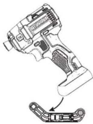
natural_image
Technical line drawing of a key driver tool with a separate exploded view showing internal components (no text or labels)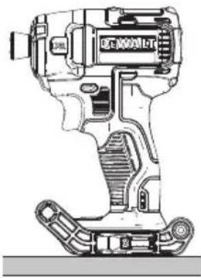
natural_image
Technical line drawing of a mechanical device with no visible text or symbolsFig. D Fig. E
natural_image
Technical illustration of a mechanical assembly with directional arrows indicating motion (no text or symbols)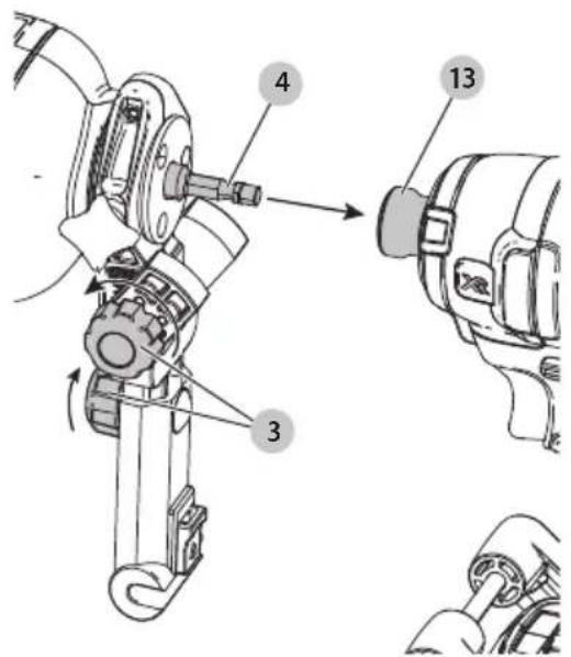
Fig. F Fig. G
natural_image
Technical illustration of a robotic arm with force arrows indicating movement or force direction (no text or symbols present)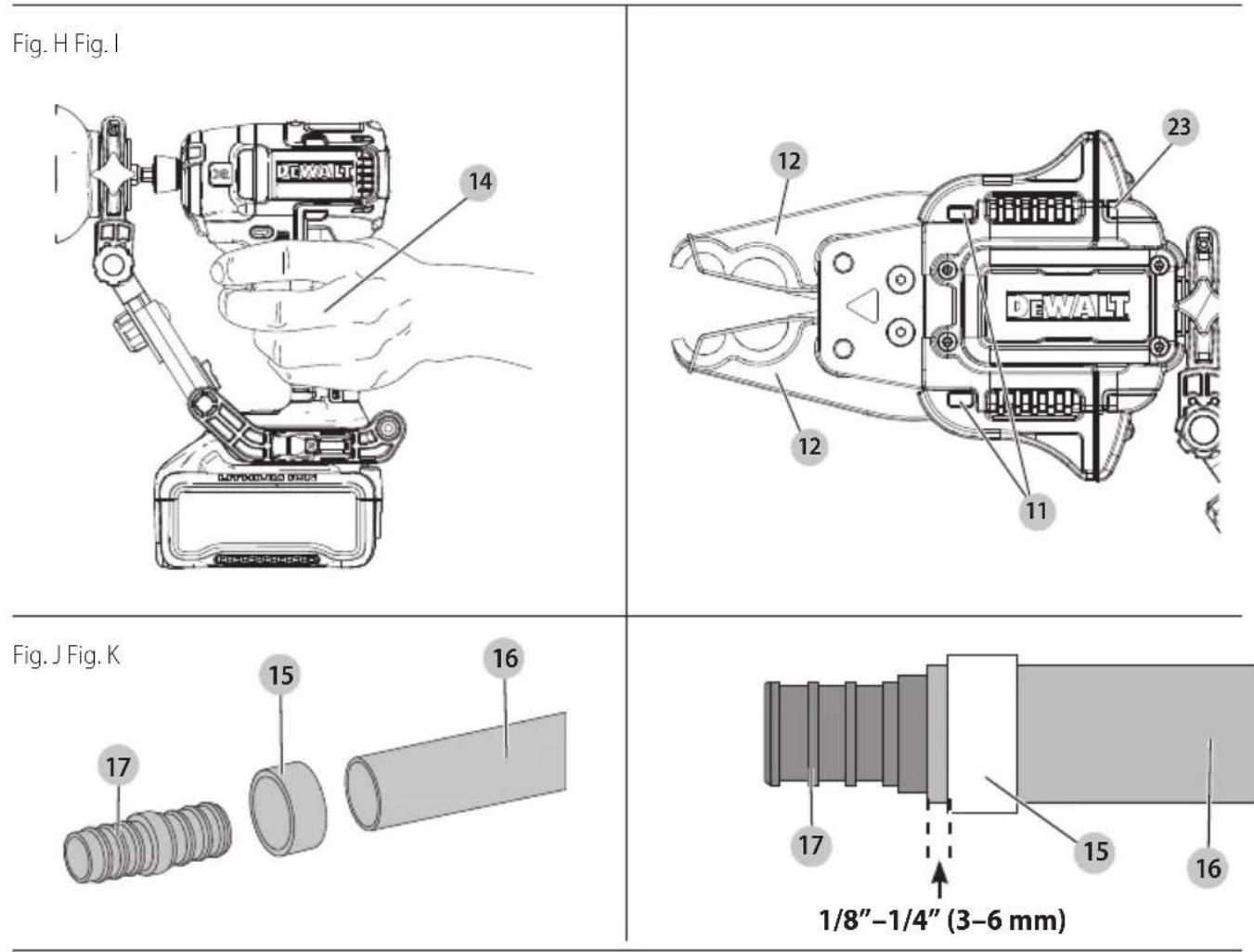
Fig. L
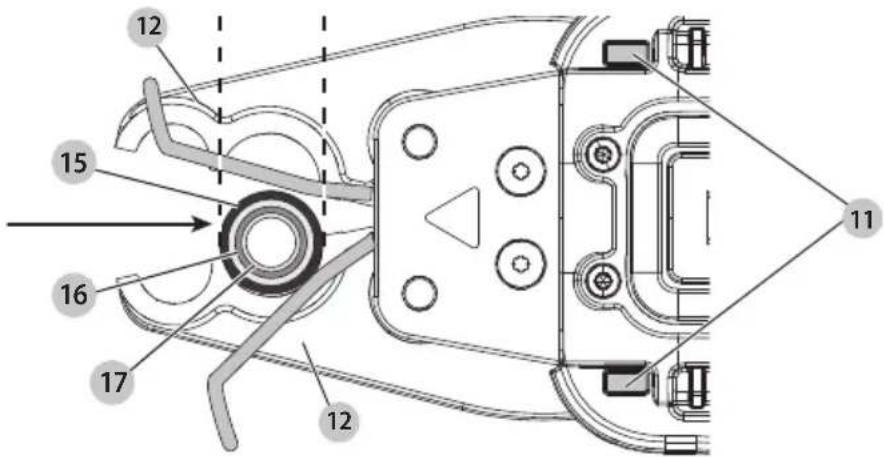
Fig. M
English
Intended Use
The DWAPXCIR is designed to install copper crimp rings that meet ASTM F1807 requirements. Only trained personnel should operate this tool.
The DWAPXCIR is designed for use with impact drivers that have an operating speed less than 4,000 RPM and a maximum torque rating of less than 280 Nm (2,500 in-lb). If using with a higher performing impact driver, select a mode which has a speed of less than 4,000 RPM and maximum torque rating that is less than 280 Nm (2,500 in-lb).
DO nOT use this attachment with drill/driver. This attachment is approved only for use with an impact driver.
DO nOT use in the presence of flammable liquids or gases.
DO nOT let children come into contact with the tool. Supervision is required when inexperienced operators use this tool.
Definitions: Safety Alert Symbols and Words
This instruction manual uses the following safety alert symbols and words to alert you to hazardous situations and your risk of personal injury or property damage.
▲ANGER: Indicates an imminently hazardous situation which, if not avoided, will result in death or serious injury.
WARNING: Indicates a potentially hazardous situation which, if not avoided, could result in death or serious injury.
CAUTION: Indicates a potentially hazardous situation which, if not avoided, may result in minor or moderate injury.
(Ased without word) Indicates a safety related message. NOTICE: Indicates a practice not related to personal injury which, if not avoided, may result in property damage.
Safety Rules for PEX Crimp Ring Press Attachment
WARNING: Read and understand these instructions and those for the attached power tool. Before use, ensure the attachment is properly attached to the tool.
WARNING: Use the PEX crimp ring press attachment only with DEWALT or DEWALT-approved accessories. Other uses or modifying the attachment for other applications may damage the attachment, damage the accessories and/or can result in a faulty installation. Faulty installation can result in failures, injury to installers and damage to property.
WARNING: When using this PEX crimp ring press attachment for installing fittings, the preparation of the cut and installation of the fitting should follow recommendations from the fitting manufacturer for proper installation procedures. Proper preparation and installation is the responsibility of the installer.
- Only trained personnel should operate this tool.
- Keep all body parts away from the attachment during operation and any time the power is ON. A moment of inattention while operating power tools may result in serious personal injury. Fingers or hands can be crushed, fractured or amputated if they become caught in the attachments.
- Inspect tool and attachments before use for any loose or missing parts. Never attempt to repair or use a damaged PEX crimp ring press attachment, brace or other attachment. Replace with a new press attachment or brace.
- This tool produces large forces that can break attachments or parts and cause injury. Always be attentive and take proper safety precautions, including wearing eye protection.
- Before operating, inspect job site for hazards including chemicals or waste that can remain in pipes.
- Before operating, read and understand all safety and operating instructions including the fitting manufacturer's installation instructions and the instructions for any other equipment used with this tool.
Failure to follow all instructions and warnings may result in property damage and/or serious personal injury.
- Keep the working area of the attachment free from hands and other objects while the tool is in use. Fingers could be crushed.
- Secure and support the material prior to making the press to prevent movement during pressing.
- Pressing operations may cause material pieces to fly. Flying particles can cause permanent eye damage. Always wear eye protection.
• Always wear gloves when operating tool and handling materials. The ends of materials can be sharp and cause serious personal injury.
Additional Safety Information
WARNING: Never modify the power tool or any part of it. Damage or personal injury could result.
WARNING: ALWAYS use safety glasses. Everyday eyeglasses are NOT safety glasses. Also use face or dust mask if cutting operation is dusty. ALWAYS WEAR CERTIFIED SAFETY EQUIPMENT:
• ANSI Z87.1 eye protection (CAN/CSA Z94.3),
• ANSI S12.6 (S3.19) hearing protection,
• NIOSH/OSHA/MSHA respiratory protection.
WARNING: Some dust created by power sanding, sawing, grinding, drilling, and other construction activities contains chemicals known to the State of California to cause cancer, birth defects or other reproductive harm. Some examples of these chemicals are:
- lead from lead-based paints,
• crystalline silica from bricks and cement and other masonry products, and
• arsenic and chromium from chemically-treated lumber. Your risk from these exposures varies, depending on how often you do this type of work. To reduce your exposure to these chemicals: work in a well ventilated area, and work with approved safety equipment, such as those dust masks that are specially designed to filter out microscopic particles.
- Wear protective clothing and wash exposed areas with soap and water. Allowing dust to get into your mouth, eyes, or lay on the skin may promote absorption of harmful chemicals. Direct particles away from face and body.
- Use the appropriate dust extractor vacuum to remove the vast majority of static and airborne dust. Failure to remove static and airborne dust could contaminate the working environment or pose an increased health risk to the operator and those in close proximity.
- Use clamps or other practical ways to secure and support the workpiece to a stable platform. Holding the work by hand or against your body is unstable and may lead to loss of control and injury.
• Air vents often cover moving parts and should be avoided. Loose clothes, jewelry or long hair can be caught in moving parts.
AUTION: When not in use, place tool on its side on a stable surface where it will not cause a tripping or falling hazard. Some tools with large battery packs will stand upright on the battery pack but may be easily knocked over.
The label on your tool may include the following symbols. The symbols and their definitions are as follows:
V....volts
Hz......hertz
min......minutes
or DC.....direct current
Class I Construction (grounded)
.../min.....per minute
BPM.....beats per minute
ClassII Construction (double insulated)
n_0 .....no load speed n .....rated speed PSI..... pounds per square inch
earthing terminal
⚠️ safety alert symbol
▲......visible radiation—do not stare into the light
......wearrespiratory protection
∞ .... wear eye protection
O....wearhearing protection
read all documentation
do not expose to rain
ASSEMBLY AND ADJUSTMENTS
WARNING: To reduce the risk of serious personal injury, DO NOT use the universal brace bracket or brace arm for tethering or securing the tool to a person or object during use when elevated.
WARNING: To reduce the risk of serious personal injury, remove the battery pack before making any adjustments, removing/installing the brace bracket, attachments, or accessories, and while transporting. An accidental start up can cause injury.
WARNING: Never modify this device or any part of it. Damage or personal injury could result.
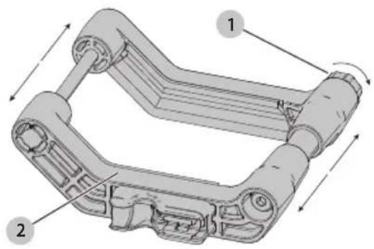
Attaching the Universal Brace Bracket (Fig. B–D)
-
Remove the battery from your impact driver. NOTE: DO NOT reinstall the battery until AFTER the brace bracket is installed.
-
Loosen the back knob 1 until the brace bracket 2 can open wide enough to slip the impact driver through as shown in Fig. B.
-
Slide the impact driver into the brace bracket from the top as shown in Fig. C.
-
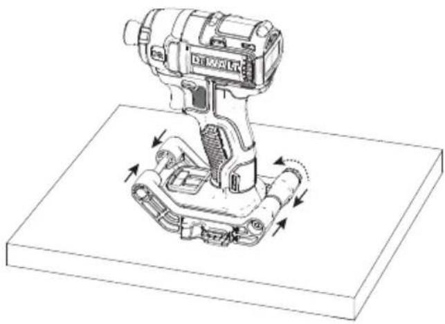
Place the impact driver and brace bracket on a FLAT surface.
-
Compress the front end together until the brace bracket is snug around the impact driver foot, then tighten the back knob. Both sides should remain parallel during tightening as shown in Fig. D.
Attaching the Brace Arm and Impact Connect Attachment (Fig. E–G)
-
Loosen both of the yellow arm knobs 3 one turn and insert the attachment shank 4 into the impact driver chuck 13 as shown in Fig. E.
-
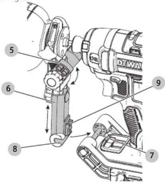
Rotate the arm joint 5 and the arm slider 6 until the bar 7 clicks into the bar channel 8. There will be an audible clicking as you rotate. The yellow slide lock 9 should secure the bar in place as shown in Fig. F.
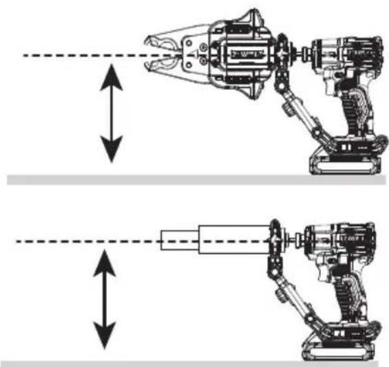
- Ensure the shank is parallel to the ground and finger tighten all knobs as shown in Fig. G.
- Reinstall the battery AFTER installation and prior to use.
Scan QR code for installation video.

OPERATION
WARNING: To reduce the risk of serious personal injury, turn unit off and remove the battery pack before making any adjustments or removing/installing attachments or accessories. An accidental start-up can cause injury.
WARNING: Proper material preparation and installation is the responsibility of the installing contractor.
WARNING: The tubing and hardware must be used in compliance with applicable building codes and as approved by the authorities having jurisdiction. For proper installation procedures and to reduce the risk of failure resulting in injury or property damage, follow all published safety and installation instructions.
AUTION: Pinch hazard. Keep fingers away from the jaws while in use.
The DWAPXCIR PEX crimp ring press attachment uses a compatible impact driver to actuate a power screw which mechanically compresses a crimp ring.
Forward setting:
- Squeezing the trigger with the impact driver set to forward (clockwise) advances the cam and compresses the jaws.
- Fully releasing the trigger switch stops the advancement of the mechanism.
Reverse setting:
- Squeezing the trigger with the impact driver set to reverse (counterclockwise) will open the jaws.
- Fully releasing the trigger switch stops the retraction of the mechanism.

WARNING: CRUSH HAZARD. Keep fingers away clamping area. Failure to do so can cause injury.
WARNING: Proper material preparation and installation is the responsibility of the installing contractor.
English
Proper Hand Position (Fig. H)
WARNING: To reduce the risk of serious personal injury, ALWAYS use proper hand position as shown.
WARNING: To reduce the risk of serious personal injury, ALWAYS hold securely in anticipation of a sudden reaction. Proper hand position requires one hand on the main handle 14 of the impact driver.
Pressing a PEX Crimp Ring (Fig. I–L)
For use with:
- PEX-B pipe.
- Brass or poly alloy couplings.
- Set the impact driver to reverse (couterclockwise) and depress the trigger of the impact driver to fully open the jaws 12 until an audible click is heard from the DWAPXCIR.
- Slide a new crimp ring 15 onto the PEX tube 16 and insert the coupling 17.
- Position the crimp ring 15 approximately 1/8"-1/4" from the end of the PEX tube and the coupling 17, per the fitting manufacturer's instructions, as shown in Fig. L.
NOTE: Before crimping, ensure the crimp ring 15 fits properly on the coupling 17 and PEX tube 16. - Secure PEX tubing to prevent it from moving while crimping.
- Position the DWAPXCIR opening of the jaws 12 that corresponds to the size of the crimp ring 15 over the crimp ring 15 as shown in Fig. L.
- Set the impact driver to forward (clockwise). Depress the trigger of the impact driver.
- The crimp is complete when you hear an audible click and the viewing windows 11 are fully green. Release the trigger.
- Set the impact driver to reverse (couterclockwise) and depress the trigger of the impact driver to allow for removal from the crimp ring from the jaws 12 until an audible click is heard from the DWAPXCIR.
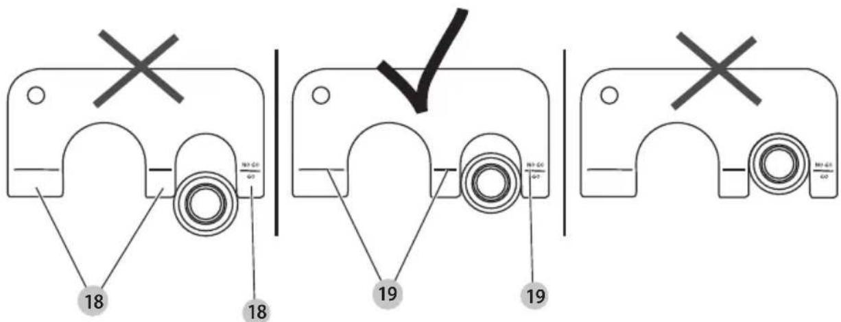
Using the Go/No-Go Gauge (Fig. M)
- Remove the battery from the tool.
- After each PEX crimp, the quality of the crimp should be verified with the provided go/no-go gauge 10.
- Insert the pressed crimp ring 15 into the go/no-go gauge 10 for the corresponding crimp ring diameter.
- If the go/no-go gauge 10 is not able to be inserted to the GO position 18, the tool will need to be adjusted by reducing the numeric setting on the eccentric cam.
- If the crimp ring 15 slides into the slot and stops on the GO range shoulder 19, the crimp is good.
- If the ring slides all the way into the slot, then the crimp ring is compressed too small and is a "NO-GO". The tool will need to be adjusted by increasing the numeric setting on the eccentric dial 33.
MAINTENANCE
WARNING: To reduce the risk of serious personal injury, turn unit off and remove the battery pack before making any adjustments or removing/installing attachments or accessories. An accidental start-up can cause injury.
Your DEWALT power tool has been designed to operate over a long period of time with a minimum of maintenance. Continuous satisfactory operation depends upon proper tool care and regular cleaning.
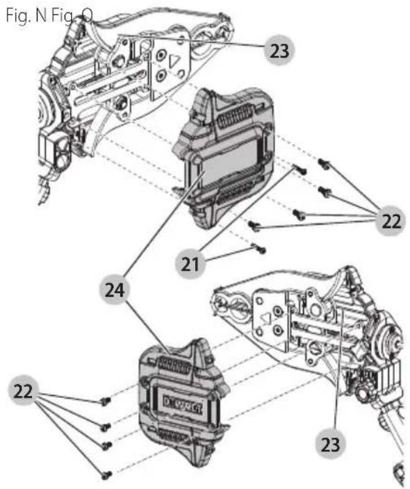
Adjusting the Calibration of the Eccentric Pin (Fig. N-Q)
WARNING: To reduce the risk of serious personal injury, remove the battery pack before making any adjustments, removing/installing the brace bracket, attachments, or accessories, and while transporting. An accidental start-up can cause injury.
NOTE: DEWALT PEX crimp ring press attachments are factory adjusted. Calibration of the eccentric dial 33 is necessary if the crimp attachment does not pass the go/no-go gauge 10 test.
- Lay the DWAPXCIR on a secure flat surface and remove the two T10 screws 21 and eight T20 screws 22 from the housing 23.
- Pull the cover 24 off the housing 23.
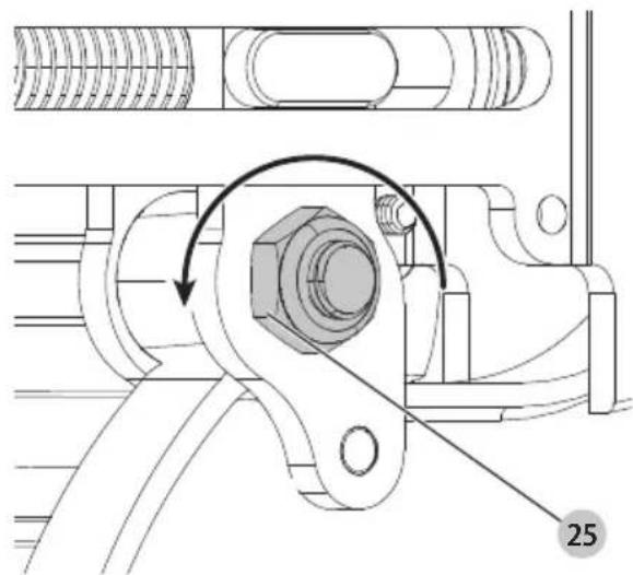
- Loosen the nut 25 opposite the numerically marked eccentric dial 33.
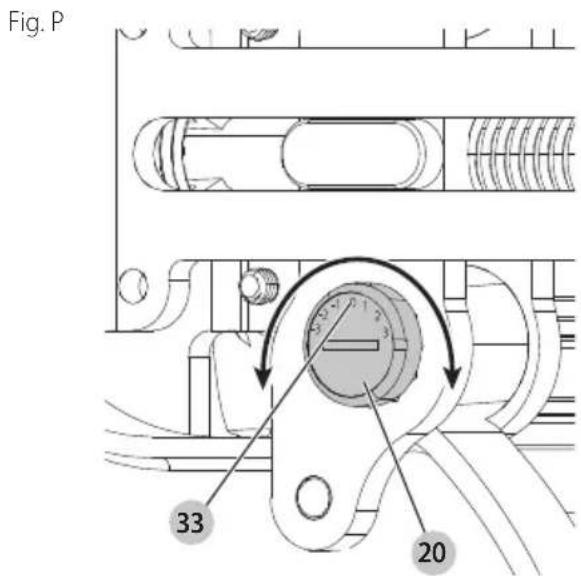
Twisting the dial to the + side will increase the crimp gap. Twisting the dial to the - side will decrease the crimp gap.
- To increase the numerical setting on the eccentric dial 33, use a coin, key or slotted bit to rotate the eccentric pin 20 counterclockwise.
To decrease the numerical setting on the eccentric dial 33, use a coin, key or slotted bit to rotate the eccentric pin 20 clockwise.
NOTE: The numerical setting should only be adjusted by an increment of one and then retested using the go/no-go gauge 10.
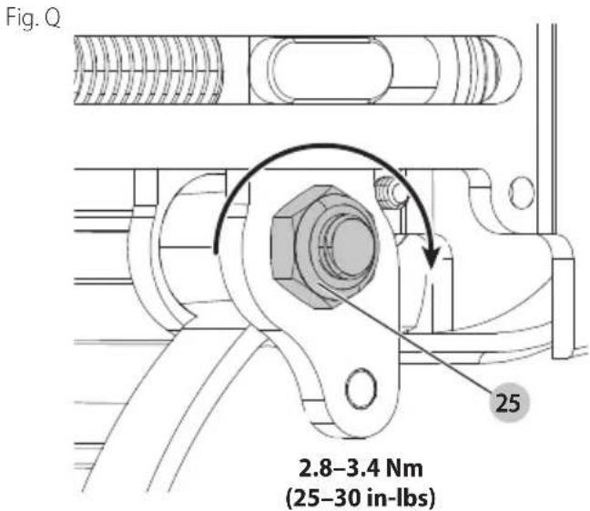
- Once the eccentric dial 33 is set, tighten the nut 25 opposite the eccentric dial 33 to 2.8–3.4 Nm (25–30 in-lb).
- Reinstall the cover 24. The two T10 screws 21 should be tightened to 1.0–1.2 Nm (9–11 in-lb). The eight T20 screws 22 should be tightened to 2.0–2.6 Nm (18–23 in-lb).
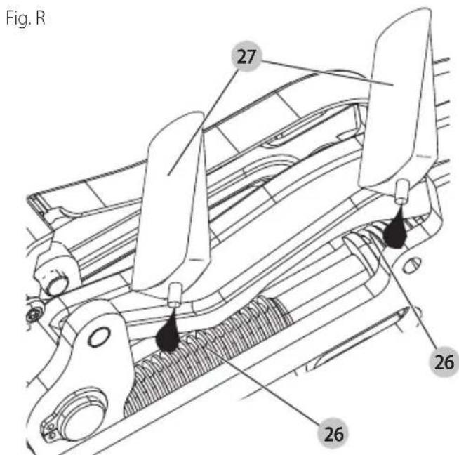
Lubricating Threaded Rod (Fig. N, R)
- Your DWAPXCIR may require the threaded rod 26 to be greased after an extensive service life.
- Lay the DWAPXCIR on a secure flat surface and remove the two T10 screws 21 and four T20 screws 22 from the housing 23.
- Pull the cover 24 off to reveal the threaded rod 26.
- Apply a small amount of DEWALT N017298 grease 27 to the areas of the threaded rod 26 as shown in Fig. R.
- Place the cover 24 onto the housing 23 and install the four T20 screws 22. Tighten the two T10 screws 21 to 1–1.2 Nm (9–11 In-lbs) and tighten the four T20 screws 22 to 2–2.6 Nm (18–23 In-lbs).
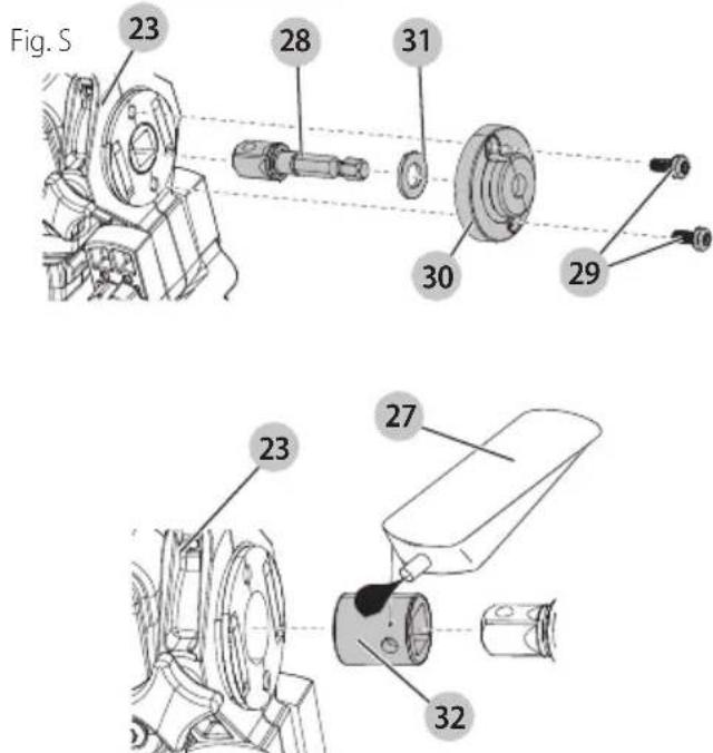
Replacing the 1/4" hex to 3/8" Square Socket Adapter (Fig. S)
The 1/4" hex to 3/8" square socket adapter 28 is designed to be replaceable in the event of a failure.
- Remove two T20 screws 29 from the support collar cap 30 and pull the support collar cap away from the housing 23.
- Remove the washer 31, and the failed adapter.
- Pull out the support collar 32 from the tool and apply a small amount of DeWALT N017298 grease to the outer surface of the support collar 32 and then reinstall the adapter into the tool.
-
Reinstall a new 1/4" hex to 3/8" square socket adapter into the opening in the support collar 32.
-
Reinstall the washer 31 over the shank, against the bottom flange of the 3/8" square socket adapter.
- Reinstall the support collar cap 30 and insert the two T20 screws 29. The two T20 screws 29 should be tightened to 2.0–2.6 Nm (18–23 in-lb).
Cleaning
WARNING: Blow dirt and dust out of all air vents with clean, dry air at least once a week. To minimize the risk of eye injury, always wear ANSI Z87.1 approved eye protection when performing this procedure.
WARNING: Never use solvents or other harsh chemicals for cleaning the non-metallic parts of the tool. These chemicals may weaken the plastic materials used in these parts. Use a cloth dampened only with water and mild soap. Never let any liquid get inside the tool; never immerse any part of the tool into a liquid.
Storage
Always store your DWAPXCIR with the battery removed from the impact driver.
Store the DWAPXCIR in a place that is as cool and dry as possible.
Accessories
WARNING: Since accessories, other than those offered by DEWALT, have not been tested with this product, use of such accessories with this product could be hazardous. To reduce the risk of injury, only DEWALT recommended accessories should be used with this product.
Recommended accessories for use with your product are available at extra cost from your local dealer or authorized service center. If you need assistance in locating any accessory, please contact DEWALT. Call 1-800-4-DEWALT (1-800-433-9258) or visit our website: www.dewalt.com
Repairs
Any tool that needs repair, is found to be worn, or operates abnormally SHALL BE REMOVED FROM SERVICE UNTIL REPAIRED. It is recommended that necessary repairs be made by a manufacturer's authorized repair facility if repairs are permitted by the manufacturer.
WARNING: To assure product SAFETY and RELIABILITY, repairs, maintenance and adjustment (including brush inspection and replacement, when applicable) should be performed by a factory service center or an authorized service center. Always use identical replacement parts.
Alterations
WARNING: Because of potential hazards associated with this type of equipment, no modifications shall be made to the product.
Register Online
Thank you for your purchase. Register your product now for:
- WARRANTY SERVICE: Registering your product will help you obtain more efficient warranty service in case there is a problem with your product.
- CONFIRMATION OF OWNERSHIP: In case of an insurance loss, such as fire, flood or theft, your registration of ownership will serve as your proof of purchase.
- FOR YOUR SAFETY: Registering your product will allow us to contact you in the unlikely event a safety notification is required under the Federal Consumer Safety Act.
Register online at www.dewalt.com/account-login.
Three-Year Limited Warranty
For warranty terms, go to
www.dewalt.com/support/warranty.
To request a written copy of the warranty terms, contact: Customer Service at DEWALT Industrial Tool Co., 701 East Joppa Road, Towson, MD 21286 or call 1-800-4-DEWALT (1-800-433-9258).
LATIN AMERICA: This warranty does not apply to products sold in Latin America. For products sold in Latin America, see country-specific warranty information contained in the packaging, call the local company or see website for warranty information.
FREE WARNING LABEL REPLACEMENT: If your warning labels become illegible or are missing, call 1-800-4-DEWALT (1-800-433-9258) for a free replacement.
FRAnÇAis
Utilisation prévue
FRANÇAIS
FONCTIONNEMENT
--- o CD.....corriente directa
OPERACIÓN
PART NUMBER
DEWALT Industrial Tool Co., 701 East Joppa Road, Towson, MD 21286
Copyright © 2024
The following are trademarks for one or more DEWALT power tools: the yellow and black color scheme, the "D" shaped air intake grill, the array of pyramids on the handgrip, the kit box configuration, and the array of lozenge-shaped humps on the surface of the tool.