DVL-E36ASSX - Basket Zephyr - Free user manual and instructions
Find the device manual for free DVL-E36ASSX Zephyr in PDF.

User questions about DVL-E36ASSX Zephyr
0 question about this device. Answer the ones you know or ask your own.
Ask a new question about this device
Download the instructions for your Basket in PDF format for free! Find your manual DVL-E36ASSX - Zephyr and take your electronic device back in hand. On this page are published all the documents necessary for the use of your device. DVL-E36ASSX by Zephyr.
USER MANUAL DVL-E36ASSX Zephyr
natural_image
Isometric technical drawing of a ceiling structure with mounting brackets and ventilation slots (no text or symbols)
RANGE HOOD - Installation instructions
ENGLISH....3
FRANÇAIS......27
Table of Contents
SAFETY INSTRUCTIONS....pag. 4
LIST OF MATERIALS....pag. 8
DUCTING CALCULATION SHEETS....pag. 9
HOODSPECIFICATION....pag.10
INSTALLATION
- INTERNAL BLOWER....pag. 11
- EXTERNAL & IN-LINE BLOWER PREPARATION....pag. 13
- DUCTING OPTIONS....pag. 15
- MOUNTING THE RANGE HOOD....pag. 16
- POWER SUPPLY CONNECTION....pag. 19
TOUCH CONTROL....pag. 21
OPTIONAL REMOTE CONTROL....pag. 22
MAINTENANCE ......pag. 23
WIRING DIAGRAMS....pag. 24
LIST OF PARTS AND ACCESSORIES ......pag. 26
WARRANTY ......pag. 27
Safety instructions 1/4
■ IMPORTANT SAFETY INSTRUCTIONS
■ READ AND SAVE THESE INSTRUCTIONS
■ PLEASE READ ENTIRE INSTRUCTIONS BEFORE PROCEEDING.
■ IMPORTANT: Save these Instructions for the Local Electrical Inspectors use.
■ INSTALLER: Please leave these Instructions with this unit for the owner.
■ OWNER: Please retain these instructions for future reference.
■ Take care when using cleaning agents or detergents.
■ Suitable for use in household cooking area.
■ WARNING - To reduce the risk of fire or electric shock, do not use this fan with any Solid-State Speed Control Device.
■ CAUTION - To reduce risk of fire and to properly exhaust air, be sure to duct air outside – Do not vent exhaust air into spaces within walls or ceilings or into attics, crawl spaces, or garages.
■ CAUTION - For general ventilating use only. Do not use to exhaust hazardous or explosive materials and vapors.
■ CAUTION - To avoid motor bearing damage and noisy and/or unbalanced impellers, keep drywall spray, construction dust, etc. off power unit.
■ CAUTION - Please read specification label on product for further information and requirements.
■ WARNING – TO REDUCE THE RISK OF FIRE, ELECTRIC SHOCK, OR INJURY TO PERSONS, OBSERVE THE FOLLOWING:
A. Use this unit only in the manner intended by the manufacturer. If you have questions, contact the manufacturer.
B. Before servicing or cleaning unit, switch power off at service panel and lock the service disconnecting means to prevent power from being switched on accidentally. When the service disconnecting means cannot be locked, securely fasten a prominent warning device, such as a tag, to the service panel.
■ WARNING - TO REDUCE THE RISK OF A RANGE TOP GREASE FIRE:
A. Never leave surface units unattended at high settings. Boilovers cause smok
Safety instructions 2/4
ing and greasy spillovers that may ignite. Heat oils slowly on low or medium settings.
B. Always turn hood ON when cooking at high heat or when flambeing foods (i.e. Crepes Suzette, Cherries Jubilee, Peppercorn Beef Flambè).
C. Clean ventilating fans frequently. Grease should not be allowed to accumulate on fan or filter.
D. Use proper pan size. Always use cookware appropriate for the size of the surface element.
E. Keep fan, filters and grease laden surface clean.
F. Use high range setting on range only when necessary. Heat oil slowly on low to medium setting.
G. Don't leave range unattended when cooking.
H. Always use cookware and utensils appropriate for the type and amount off food being prepared.
■ WARNING – TO REDUCE THE RISK OF INJURY TO PERSONS IN THE EVENT OF A RANGE TOP GREASE FIRE, OBSERVE THE FOLLOWINGa:
A. SMOTHER FLAMES with a close-fitting lid, cookie sheet, or metal tray, then turn off the burner. BE CAREFUL TO PREVENT BURNS. If the flames do not go out immediately, EVACUATE AND CALL THE FIRE DEPARTMENT.
B. NEVER PICK UP A FLAMING PAN – You may be burned.
C. DO NOT USE WATER, including wet dishcloths or towels – a violent steam explosion will result.
D. Use an extinguisher ONLY if:
-
You know you have a Class ABC extinguisher, and you already know how to operate it.
-
The fire is small and contained in the area where it started.
-
The fire department is being called.
-
You can fight the fire with your back to an exit.
^a Based on “kitchen firesafety tips” published by NFPA
Proper maintenance of the Range Hood will assure proper performance of the unit.
■ INSTALLATION INSTRUCTIONS
WARNING – TO REDUCE THE RISK OF FIRE, ELECTRIC SHOCK, OR INJURY TO PERSONS, OBSERVE THE FOLLOWING:
A. Installation work and electrical wiring must be done by qualified person(s) in accordance with all applicable codes and standards, including fire-rated construction.
Safety instructions 3/4
B. Sufficient air is needed for proper combustion and exhausting of gases through the flue (chimney) of fuel burning equipment to prevent back drafting. Follow the heating equipment manufacturer's guideline and safety standards such as those published by the National Fire Protection Association (NFPA), and the American Society for Heating, Refrigeration and Air Conditioning Engineers (ASHRAE), and the local code authorities.
C. When cutting or drilling into wall or ceiling, do not damage electrical wiring and other hidden utilities.
D. Ducted fans must always be vented to the outdoors.
E. This unit must be grounded.
■ WARNING - TO REDUCE THE RISK OF FIRE, USE ONLY METAL DUCTWORK.
■ WARNING - UNDER CERTAIN CIRCUMSTANCES DOMESTIC APPLIANCES MAY BE DANGEROUS.
A. Do not check filters with hood working.
B. Do not touch the lamps after a prolonged use of the appliance.
C. No food must be cooked flambè underneath the hood.
D. The use of an unprotected flame is dangerous for the filters and could cause fires.
E. Watch constantly the fried food in order to avoid the cooking oil flares up.
F. Before performing any maintenance operation, disconnect the hood from the electrical service.
■ The manufacturers will not to accept any responsibility for eventual damages, because of failure to observe the above instructions.
Electrical Requirements
Important:
- Observe all governing codes and ordinances.
- It is the customer's responsibility to be aware of these below:
- To contact a qualified electrical installer.
- To assure that the electrical installation is adequate and in conformance with National Electrical Code, ANSI/NFPA 70 latest edition* or CSA standards C22.1-94, Canadian Electrical Code, Part 1 and C22.2 No.0-M91 - latest edition** and all local codes and ordinances.
- If codes permit and a separate ground wire is used, it is recommended that a qualified electrician determine that the ground path is adequate.
- Do not ground to a gas pipe.
- Check with a qualified electrician if you are not sure the range hood is properly grounded.
Safety instructions 4/4
- Do not have a fuse in the neutral or ground circuit.
- This appliance requires a 120V 60Hz electrical supply and connected to an individual properly grounded branch circuit protected by a 15 or 20 ampere circuit breaker or time delay fuse. Wiring must be 2 wire with ground. Please also refer to Electrical Diagram on product.
- A cable locking connector (not supplied) might also be required by local codes. Check with local requirements, purchase and install appropriate connector if necessary.
* National Fire Protection Association Batterymarch Park, Quincy, Massachusetts 02269
** CSA International 8501 East Pleasant Valley Road, Cleveland, Ohio 44131-5575
Federal Communication Commission Interface Statement
- This equipment has been tested and found to comply with the limits for a Class B digital device, pursuant to Part 15 of the FCC Rules. These limits are designed to provide reasonable protection against harmful interference in a residential installation.
- This equipment generates, uses and can radiate radio frequency energy and, if not installed and used in accordance with the instructions, may cause harmful interference to radio communications. However, there is no guarantee that interference will not occur in a particular installation. If this equipment does cause harmful interference to radio or television reception, which can be determined by turning the equipment off and on, the user is encouraged to try to correct the interference by one of the following measures:
- Reorient or relocate the receiving antenna.
- Increase the separation between the equipment and receiver.
- Connect the equipment into an outlet on a circuit different from that to which the receiver is connected.
- Consult the dealer or an experienced radio/TV technician for help.

WARNING Prop. 65 Warning for California Residents: This product may contain chemicals known to the State of California to cause cancer, birth defects, or other reproductive harm.
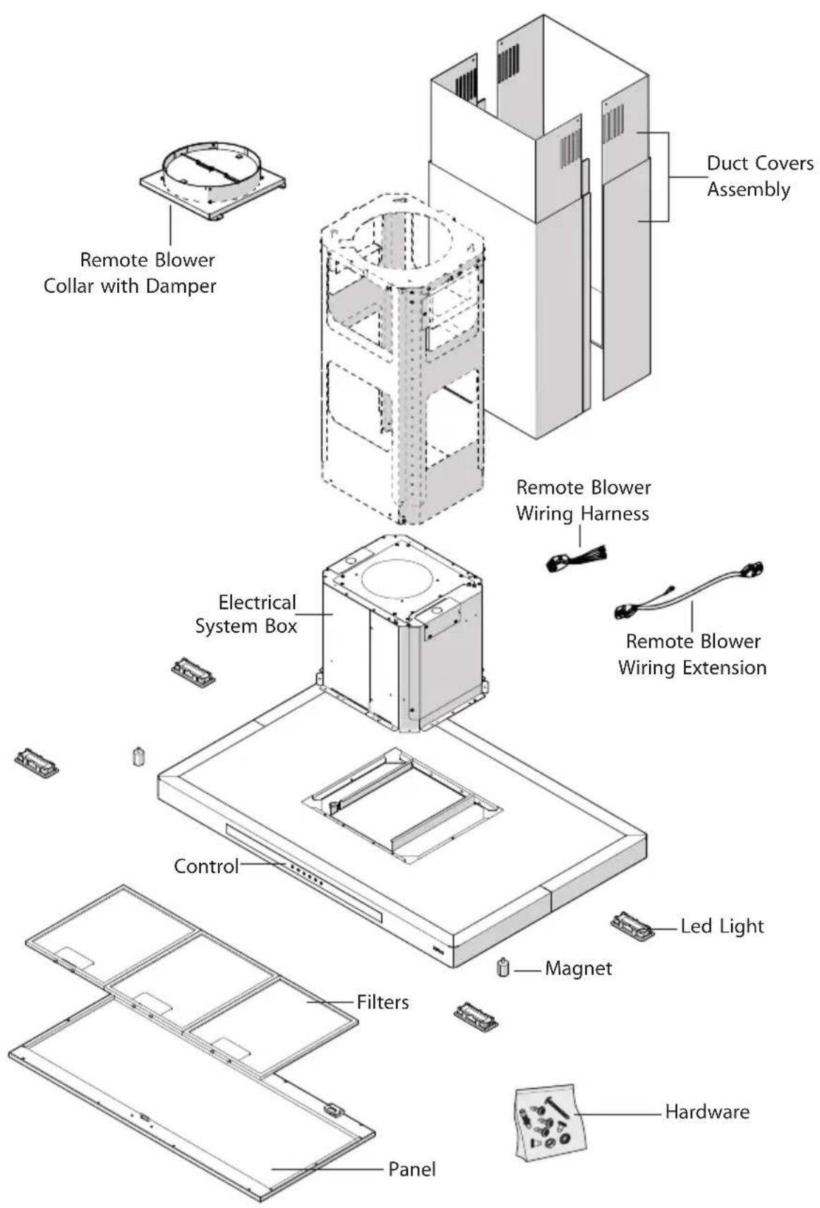
List of Materials
text_image
Remote Blower Collar with Damper Duct Covers Assembly Remote Blower Wiring Harness Electrical System Box Control LED Light Magnet Filters Panel HardwareDucting Calculation Sheet
| Duct pieces | Equivalent number length x used = | Total | |
 | 3- 1/ 4" x 10" Rect., straight | 1 Ft. x ( ) = | Ft. |
 | 6", 7", 8", 10" Round, straight | 1 Ft. x ( ) = | Ft. |
 | 3- 1/ 4" x 10" Rect. 90° elbow | 15 Ft. x ( ) = | Ft. |
 | 3- 1/ 4" x 10" Rect. 45 elbow | 9 Ft. x ( ) = | Ft. |
 | 3- 1/ 4" x 10" Rect. 90 flat elbow | 24 Ft. x ( ) = | Ft. |
 | 7" to 6" or 8" to 7" Round tapered reducer | 25 Ft. x ( ) = | Ft. |
 | 6", 7", 8" Round in-line damper | 15 Ft. x ( ) = | Ft. |
 | 6", 7", 8", 10" Round, 90° elbow | 15 Ft. x ( ) = | Ft. |
 | 6", 7", 8", 10" Round, 45° elbow | 9 Ft. x ( ) = | Ft. |
| Subtotal column 1 = | Ft. | ||
Maximum Duct Length: For satisfactory air movement, the total duct length should not exceed 150 equivalent feet.
| Duct pieces | Equivalent number length x used = | Total | |
 | 3- 1/ 4" x 10" Rect. to 6" round transition | 5 Ft. x ( ) = | Ft. |
 | 3- 1/ 4" x 10" Rect. to 6" round transition 90° elbow | 20 Ft. x ( ) = | Ft. |
 | 6" round to 3- 1/ 4" x 10" rect. transition | 1 Ft. x ( ) = | Ft. |
 | 6" round to 3- 1/ 4" x 10" rect. transition 90° elbow | 16 Ft. x ( ) = | Ft. |
 | 7" round to 3 1/ 4" x 10" rect. transition | 8 Ft. x ( ) = | Ft. |
 | 7" round to 3- 1/ 4" x 10" rect. transition 90° elbow | 23 Ft. x ( ) = | Ft. |
 | 3- 1/ 4" x 10" Rect. wall cap with damper | 30 Ft. x ( ) = | Ft. |
 | 6", 7", 8", 10" Round, wall cap with damper | 30 Ft. x ( ) = | Ft. |
| [SGWH] | 6", 7", 8", 10" Round roof cap | 30 Ft. x ( ) = | Ft. |
| Subtotal column 2 = Subtotal column 1 = Total ductwork = | Ft. | ||
| Ft. | |||
| Ft. | |||
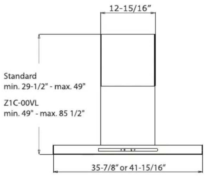
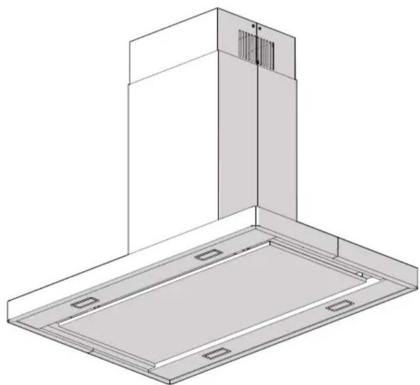
Hood Specifications
front of hood side of hood
text_image
Standard min. 29-1/2" - max. 49" Z1C-00VL min. 49" - max. 85 1/2" 12-15/16" 35-7/8" or 41-15/16"
text_image
11-1/4" 2-1/8" 23-5/8"top of hood
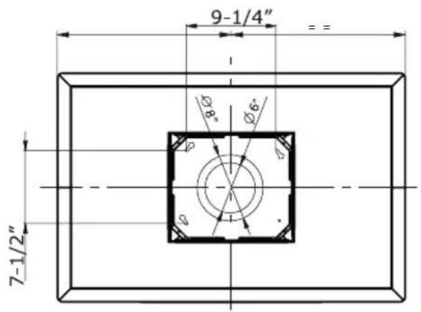
text_image
9-1/4" 7-1/2"Installation - Internal Blower
■ The following instructions are for installing the internal blower. CAUTION: To reduce the risk of fire and electric shock, install this rangehood only with internal blower models CBI-290A or CBI-600A.
For external and in-line blower preparation please turn to page 13.
- Remove the 6" round top plate and then remove the remote motor support bracket to the motor housing. See Fig.1
- Insert motor into the plate and secure using 4 screws. See Fig.2
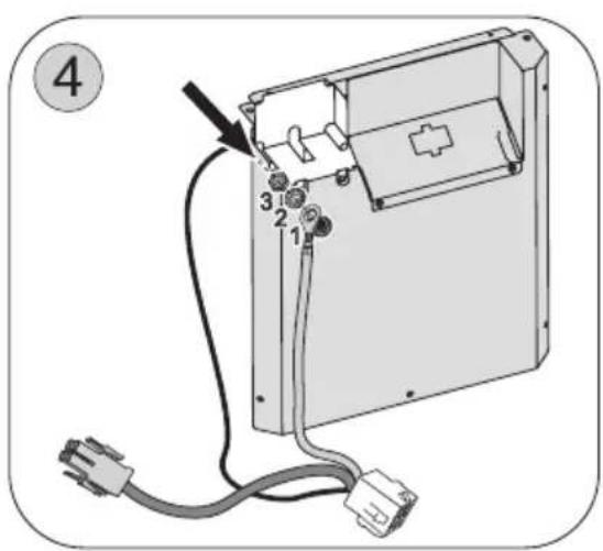
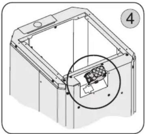
- Secure the capacitor box, connected to the supplied wire, to the bracket using 2 screws. See Fig.3
- Secure the green/yellow ground wire, connected to the wire supplied with the capacitor cable, using the screw on the bracket. Fig. 4
text_image
Diagram of an electronic device with labeled components and wiring, showing a connector with pins 1, 2, 3 and a plug terminal.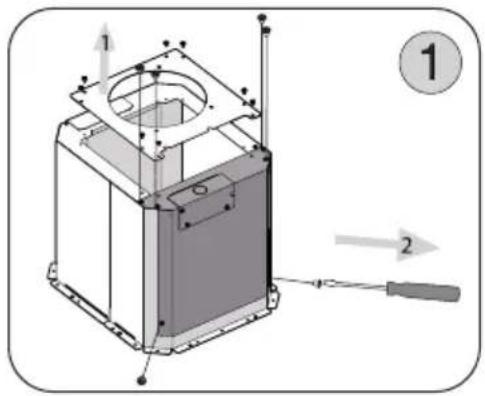
text_image
Technical diagram of a device with labeled components and directional arrows, including numbered callouts 1 and 2.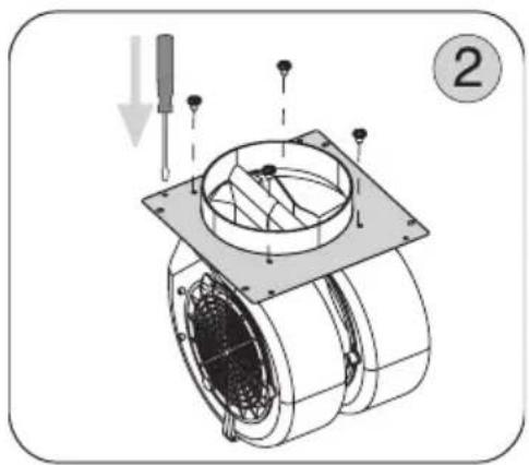
natural_image
Technical illustration of a mechanical assembly with labeled component (2), showing internal components and a downward arrow indicator (no text or symbols beyond label)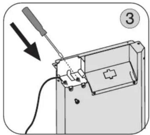
natural_image
Diagram of a mechanical device with a screwdriver inserted, showing internal components and wiring (no text or symbols)-
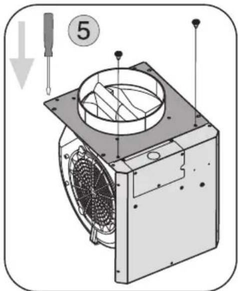
Connect the plate and the motor, on the remote motor support bracket, securing it using 2 screws. Fig. 5
-
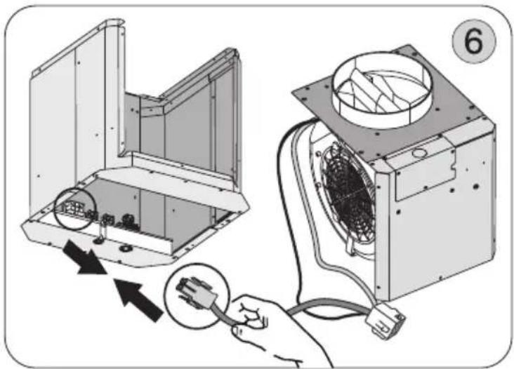
Attach the 6 pin male molex connector from blower wire to the 6 pin female molex connector located inside the blower housing. See Fig.6
-
Install the motor and bracket, inside the motor housing, completing the installation using the other screws (6) that have been supplied. Fig. 7
-
Connect 9 pin male molex connector from blower wire to 9 pin female molex connector on the capacitor wire. See Fig.8
text_image
⑤WARNING! Place electrical wiring inside the blower housing.
The hood is now ready to be installed on the wall.
natural_image
Illustration of a device being connected to an air conditioner unit, showing internal components and wiring (no text or symbols)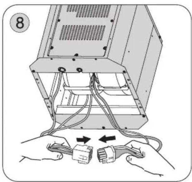
natural_image
Illustration of hands connecting to a computer case with cables and connectors (no text or symbols)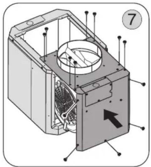
natural_image
Technical diagram of an internal device housing with labeled components and an arrow indicating direction (no text or symbols present)Installation - External & In-Line Blower Preparation
■ The following instructions are for preparing the hood for use with an external or in-line blowers models CBE-1000 or PBN-1000A.
CAUTION: To reduce the risk of fire and electric shock, install this rangehood only with remote blowers rated maximum 6.2 A.
For internal blower instructions please turn to page 11.
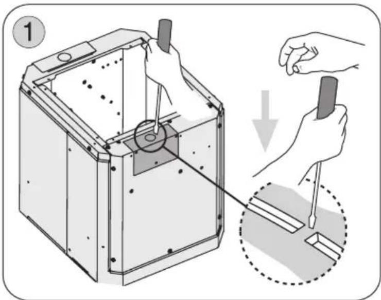
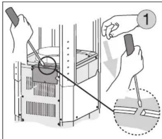
-
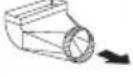
Break out the partially pre-cut circle in the lid, located on the remote motor support bracket, using a flat head screwdriver. Fig. 1
-
Remove the cover by un-doing the (3) screws. Fig. 2
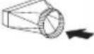
-
Replace the 6" round plate with the 8" round blower collar to top of blower housing using (4) screws. Fig.3
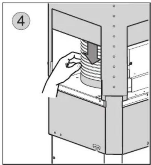
-
Insert the female connector into the remote motor support bracket enclosure. Fig.4
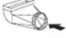
-
Pass the wires of the remote motor through the hole in the cover that was previously removed and connect them with those of the connector located in the enclosure. Fig. 5
Note: Carry out the power supply connection in accordance with the national electric code, ANSI/NFPA 70-1999.
text_image
Diagram illustrating a mechanical assembly process with labeled parts and directional arrows indicating tool movement.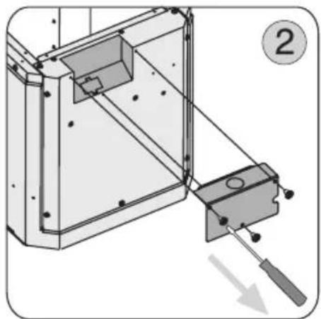
natural_image
Technical diagram of a mechanical assembly with a lever and component, no visible text or symbols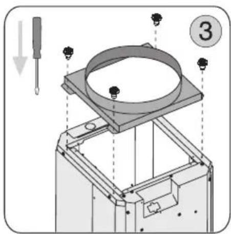
text_image
Technical diagram showing a mechanical assembly with labeled parts and directional arrows indicating motion or assembly.Note1: A cable lock (not included) may be required by local codes. Please review local codes for more information.
-
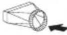
Reinstall the cover on the motor housing by following the instructions from step 2 in reverse order.
-
Attach 6 pin male molex connectors to 6 pin female molex connectors inside blower housing. See Fig. 6
Note2: Check local codes to determine minimum wire gauge.
See manual included with external and in-line blower for instructions on installing the blower.
natural_image
Technical diagram of a 3D printer or scanner component with an inset close-up showing internal components (no text or symbols)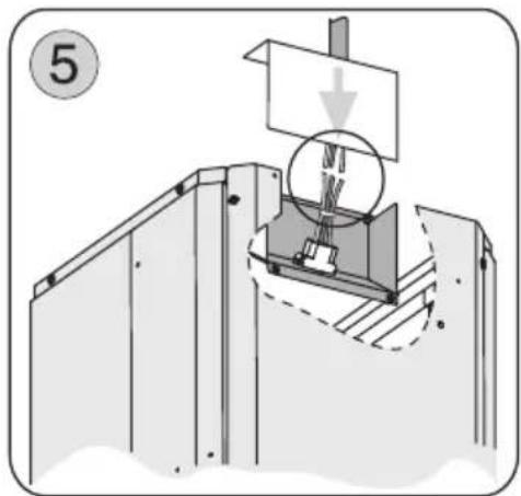
natural_image
Mechanical assembly diagram showing a rotating component with a downward arrow, no text or symbols present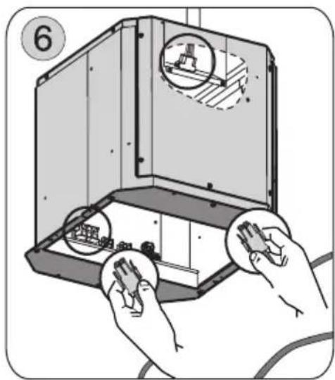
natural_image
Illustration of hands assembling a mechanical component with circular insets showing internal components (no text or symbols)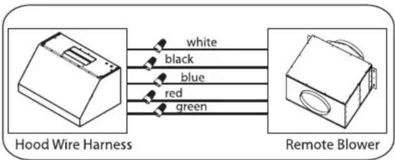
flowchart
graph LR
    A["Hood Wire Harness"] -->|white| B["Remote Blower"]
    A -->|black| B
    A -->|blue| B
    A -->|red| B
    A -->|green| B
Installation - Ducting Options
■ WARNING FIRE HAZARD
NEVER exhaust air or terminate duct work into spaces between walls, crawl spaces, ceiling, attics or garages.
All exhaust must be ducted to the outside, unless using the recirculating option.
Use single wall rigid Metal ductwork only.
Fasten all connections with sheet metal screws and tape all joints w/ certified Silver Tape or Duct Tape.
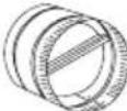
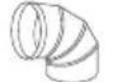
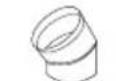
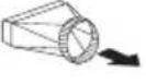
Some Ducting Options
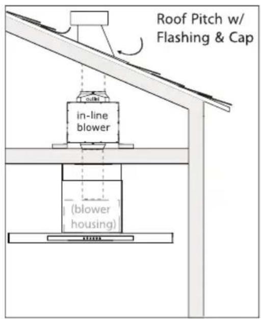
text_image
Roof Pitch w/ Flashing & Cap in-line blower (blower housing)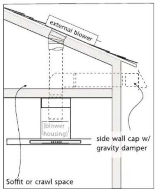
text_image
external blower (blower housing) side wall cap w/ gravity damper Soffit or crawl space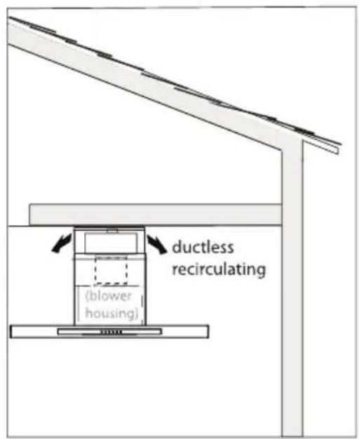
text_image
ductless recirculating (blower housing)Installation - Mounting the Range Hood
■ MOUNTING HEIGHTS
The range hood must be installed at a minimum height of 24 inches and maximum mount height of 36 inches from the cooking surface.
It is important to install the hood at the proper mounting height. Hoods mounted too low could result in heat damage and fire hazard; while hoods mounted too high will be hard to reach and will lose performance and efficiency.
Duct cover extension kit is available for taller ceiling heights.
There must be a minimum of 4-7/16 inches from the bottom of the range hood to the bottom of the lower support frame to ensure serviceability. Determine dimension X during installation planning.
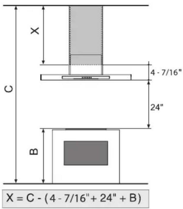
text_image
X C 4 - 7/16" 24" B X = C - (4 - 7/16" + 24" + B)■ MOUNTING TO THE CEILING
The following instructions assume the installer has access to the attic or crawl space. Each installation may be unique to the home.
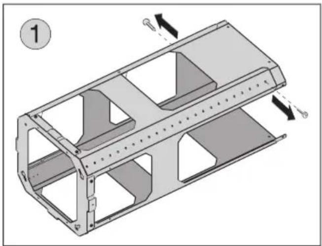
- Remove the (2) screws to unlock the top support frame from the bottom support frame. Fig.1.
natural_image
Technical illustration of a mechanical housing component with internal cavities and mounting holes (no text or symbols)Note! If you ordered a recirculating kit please refer to the instructions included inside the kits prior to installing the hood to the ceiling.

text_image
Diagram illustrating a mechanical assembly or lifting process with labeled components and directional arrows indicating motion.- Position hole template on the ceiling paying attention that the arrow is positioned on the same side as the range hood controls.
natural_image
Diagram of a mechanical lifting device with hands performing assembly (no text or symbols)- Make 3 holes in the ceiling and drive in screws without completely tightening them. Pay attention not to insert the screw into the hole marked with an X on the hole template.
- Align the ceiling bracket with the (3) screws previously installed in the ceiling. Fig. 2
Rotate assembly slightly clockwise to lock in place.
Tighten the 3 screws to secure the structure in place.
text_image
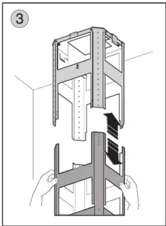
Technical diagram of a multi-level storage or rack system with labeled components and directional arrows indicating assembly or inspection.- Insert the bottom support frame into the top support frame. Fig.3
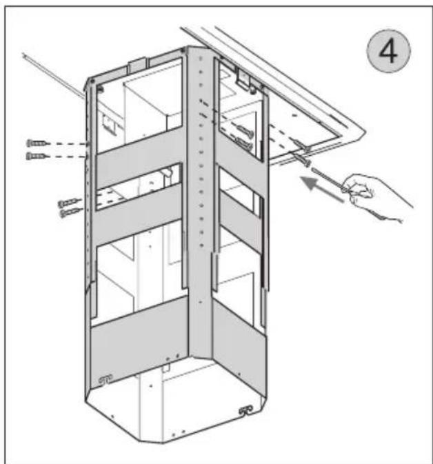
Adjust height according to your installation (see pag.16) and secure the support frames together using the (2) screws per extension arm (8 total). Fig.4
natural_image
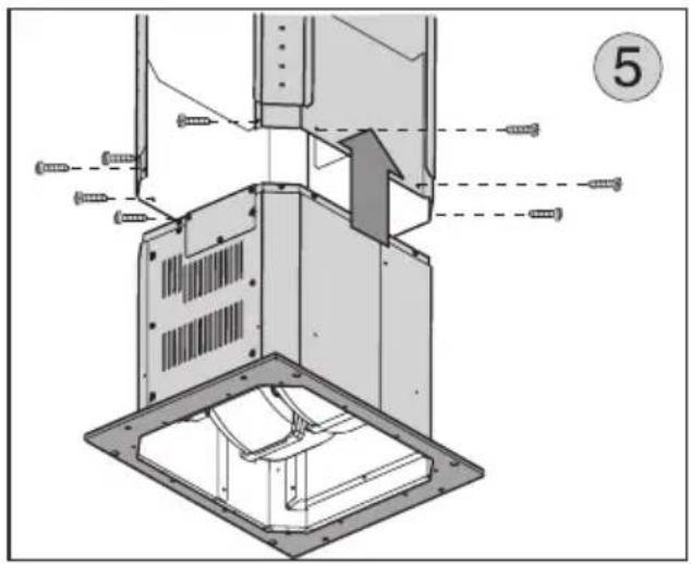
Technical diagram of a mechanical assembly with screws and a numbered label (5), showing internal components without any readable text or symbols.-
Insert the motor housing into the support frame assembly and secure it using 8 screws. Fig.5
-
Connect the equipment to the power supply by following the steps shown in the section POWER SUPPLY CONNECTION.
NOTE: For the various installations use screws and screw anchors suited to the type of ceiling (minimum screw size: 1/4" diameter x 2-3/4" length).
Installation - Power Supply Connection
GENERAL
- Carefully read the following important information regarding installation safety and maintenance. Keep this information booklet accessible for further consultations.
■ POWER SUPPLY CONNECTION
For connection to the power supply refer to the following:
- Break out the partially pre-cut circle in the cover of the mains power connection enclosure using a flatheadscrewdriver.
Fig. 1
-
Remove the power supply cover by un-doing the (2) screws. Fig. 2
-
Connect the supply conduit to the cover, then connect the hood to the power supply by making the following connections.
Fig.3:
BLACK = L line
WHITE = N neutral
GREEN / YELLOW = G ground
- A double-pole switch properly rated must be installed to provide the range hood power supply disconnection.
- Connect the electrical conduit to the Field Wiring Compartment using listed onduit fittings.
- Carry out the power supply connection in accordance with the national electric code, ANSI/NFPA 70-1999.
text_image
Diagram illustrating a mechanical assembly or inspection procedure with labeled steps and magnified detail view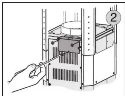
natural_image
Illustration of a hand using a tool to adjust or install a device inside a rack unit (no text or symbols visible)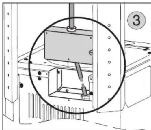
natural_image
Technical diagram of a mechanical assembly with a magnified inset showing internal components (no text or symbols)-
Replace the lid by following the instructions from step 9 in reverse order, ensuring that the tab on the lid is within the enclosure.
-
Having connected the equipment to the power supply, you can now continue with the ceiling mounting instructions.
-
Secure the correct size ducting for your installation (not supplied) to the collar on top of the housing. Fig.4
-
Secure the two upper duct covers to support frame with (4) screws. Fig.5
-
Secure the two lower duct covers parts to the support frame by overlapping the lateral magnets. Fig.6
-
Verify that ducting from hood is connected to ducting in the attic that will exhaust air out of the home.
natural_image
Illustration of a hand pressing down a cylindrical component into a machine (no text or symbols visible)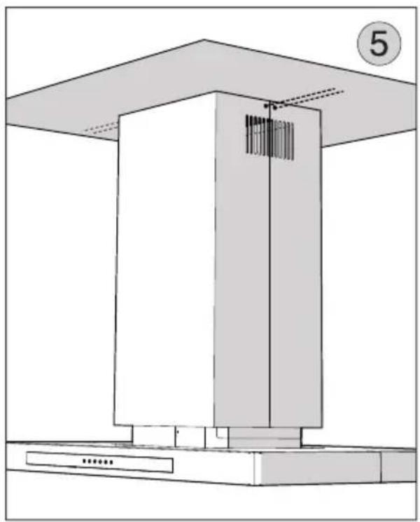
natural_image
Architectural diagram of a cabinet or enclosure with a numbered label (5) and no visible text or symbols.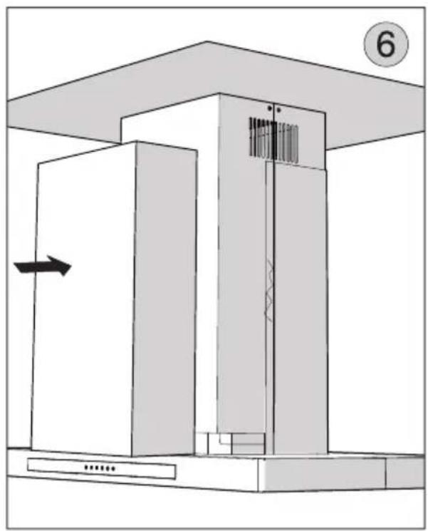
natural_image
Architectural diagram of a building interior with stairs, windows, and a numbered circle (no text or symbols)Touch Control
text_image
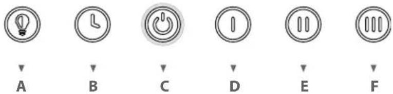
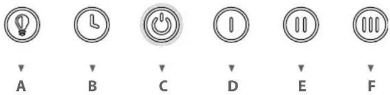
A B C D E FA – Lights Button: Lights are three level (high, medium, low). From stand-by-on mode, touch once for high, twice for medium, three times for low, four times to cycle back.
B - Delay Off Button: Press the Delay Off Button to enable the ten-minute delay-off function, no matter at what speed the fan is running at. B button will start blinking indicating the delay off function is enabled. After ten minutes the fan and lights will turn off. Delay off function can be disabled by pressing B button, changing the speed, or pressing the Power Button C.
C - Power Button: Press once to activate all button stand by mode allowing control of other button functions. All buttons will illuminate indicating stand by mode. Press the Power Button again to turn the hood off (fan and lights). The stand by mode will remain active for 30 seconds.
D - Low Speed Button: In stand-by mode: Press once for low speed.
E - Medium Speed Button: In stand-by mode: Press once for medium speed.
F - High Speed Button: In stand-by mode: Press once for high speed.
MESH FILTER CLEAN REMINDER (always enabled): after 60 hours of fan usage, button A blinks when the hood is in stand-by, indicating it is time to clean the mesh filters. To Reset the function: with the hood in stand-by, press and hold the B button for 4 to 5 seconds, the A button will stop blinking, and the 60-hour timer will reset.
CHARCOAL FILTER REPLACE REMINDER (disabled by default, must be enabled by user if recirculating hood): To enable Charcoal Filter Replacement Function hold buttons D and F simultaneously for four seconds. The A button will quickly flash 3 times indicating the Charcoal Filter Replacement Function is enabled. After 200 hours of fan usage, the B button will blink while the hood is on, indicating it is time to replace the charcoal filters. To Reset the Charcoal Filter Replace Reminder function: Hold the B button for 4 to 5 seconds until it stops flashing, and the 200-hour timer will reset.
Order replacement charcoal filter kit number Z0F-C010 through your local dealer, www.zephyronline.com, or the Zephyr customer service department.
To disable the Charcoal Filter Replacement function, repeat the enable procedure, the A button will illuminate for 3 seconds then turn off indicating the Charcoal Filter Replacement Function is disabled.
CLEAN AIR FUNCTION (disabled by default, must be enabled by the user). To enable Clean Air function, with hood in stand by, press and hold button E for 4 to 5 seconds. The E button will start blinking, the fan will turn on low speed for 10 minutes. After 10 minutes the fan will turn off and the 4-hour timer will begin. The E button led will continue blinking when Clean Air Function is enabled, even if fan is not on. When Clean Air function is enabled, every 4 hours of non-fan usage the fan will automatically turn on at low speed for 10 minutes. After 10 minutes the fan will turn off and the 4-hour timer will reset.
Optional Remote Control
SYNCHRONIZATION:
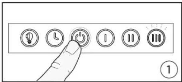
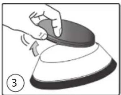
To synchronize the remote control with the range hood for the first time, proceed as follows: 1. With the range hood off, press and hold the "Power" on the hood for 4 seconds (Fig.1) until the "3rd speed" indicator on the hood flashes for 3 times. 2. Press any button on the remote control within 4 seconds to confirm the link (Fig.2). If successful, the lights of the hood will turn on. The range hood is now synchronized with the remote control. If you experience any problems, repeat the procedure.
text_image
Diagram showing a finger pressing a button with icons for lighting, time, power, alarm, and three vertical buttons labeled 1, 2, 3.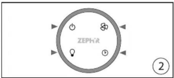
text_image
ZEPHR ②FCC Caution: To assure continued compliance, any changes or modifications not expressly approved by the party responsible for compliance could void the user's authority to operate this equipment. (Example - use only shielded interface cables when connecting to computer or peripheral device. This device complies with Part 15 of the FCC Rules. Operation is subject to the following two conditions. (1) This device may not cause harmful interference, and (2) This device must accept any interference received, including interference that may cause undesired operation.
GENERAL INFORMATION:
- Remove any protective film from the remote surface prior to using it.
- The remote control has a range of approximately 10-15 feet.
- The remote control is equipped with a magnetic base and may be attached to ferrous surface for easy storage.
- The remote top is made of a plastic material and is prone to scratches. Use care when handling and cleaning the remote; we suggest using a microfiber cloth to clean it.
- The remote control will enter a sleep mode after 20 seconds of inactivity to conserve battery life. Press any button for one second to wake the remote.
BATTERY REPLACEMENT:
The batteries will last approximately 8 months, depending on usage.
- Remove rubber cover from bottom (Fig.3).
- Using an object such as a screwdriver or pen, gently place it in the center opening in the bottom of the remote and push inwards to dislodge the top touch panel from the remote body. (Fig. 4)
- Press on the metal spring located in the battery tray to dislodge battery. Replace both batteries with type 3V CR2450 (Fig.5). Re-assemble by following instructions in reverse.
natural_image
Illustration of a hand pressing down on a circular object with a knob, labeled with number 3 (no text or symbols on the object itself)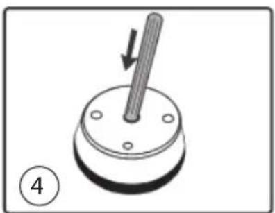
natural_image
Mechanical component diagram showing a rod inserted into a circular base with mounting holes (no text or symbols)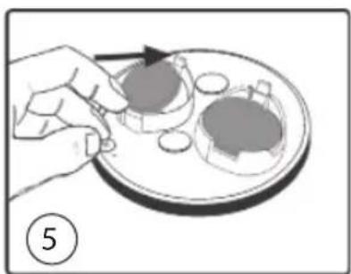
natural_image
Illustration of a hand placing a small object onto a tray with two circular objects, no text or symbols present.Maintenance
- It is recommended to operate the appliance prior to cooking. It is recommended to leave the appliance in operation for 5 minutes after cooking is completed in order to completely eliminate cooking vapors and odors. The proper function of the range hood is conditioned by the regularity of maintenance.
- The decorative mesh filters capture the grease particles suspended in the air and are therefore subject to clogging because of frequent use. In order to prevent a fire hazard, it is recommended to clean the filter a minimum of every 2 months or when instructed by the Metal Filter Clean indicator on the range hood controls. Clean the range hood by carrying out the following instructions:
- Remove the filters from the range hood and wash them in a solution of water and neutral liquid detergent, leaving to soak.
- Rinse thoroughly with warm water and leave to dry.
- Filters may also be washed in the dishwasher at the lowest setting.
The filters may alter in color after several washes but is not cause for replacement.
- Clean the blower and other surfaces of the range hood regularly using a cloth moistened with denatured alcohol or non abrasive liquid detergent.
Wiring Diagram
INTERNAL BLOWER CIRCUIT DIAGRAM
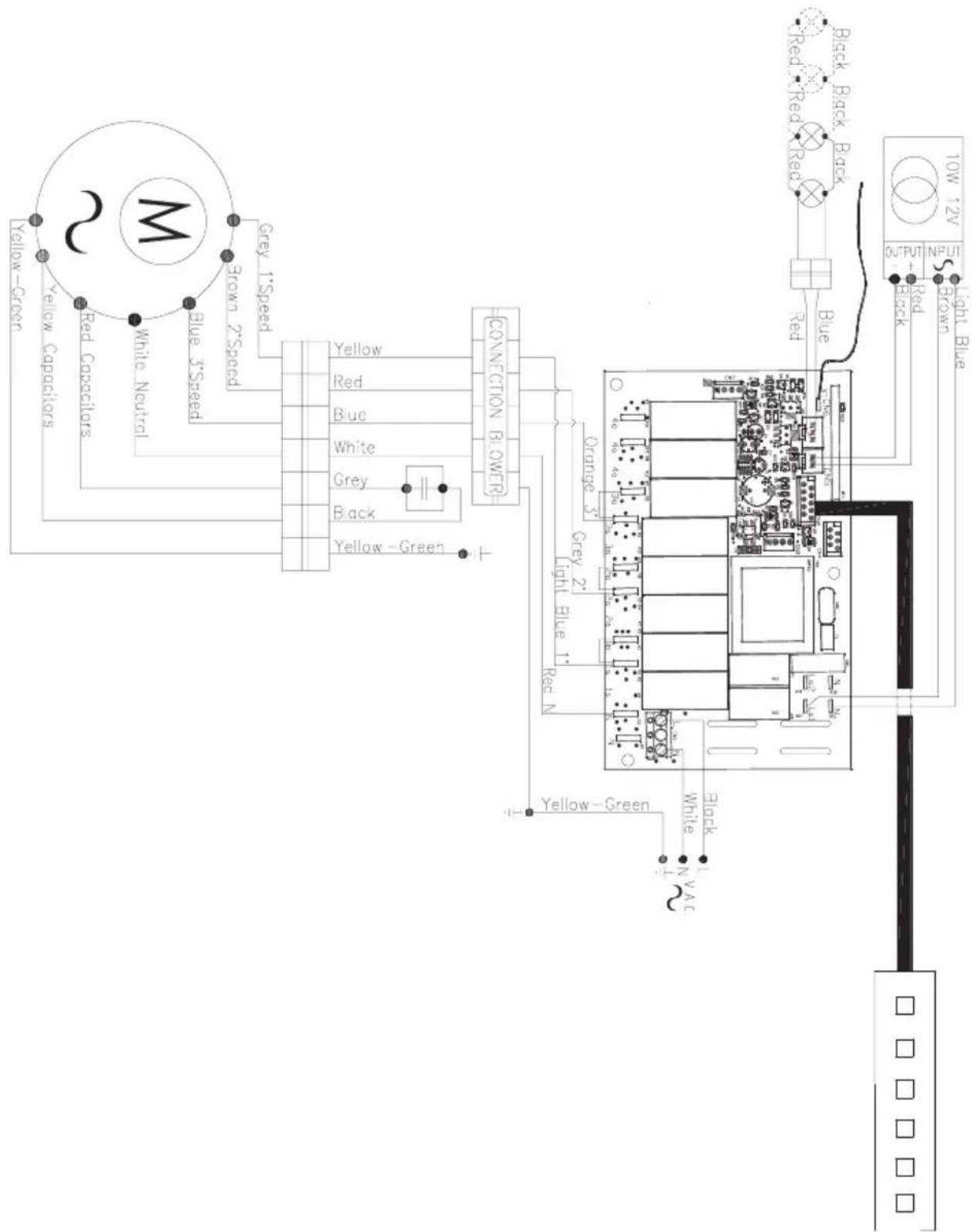
text_image
2M Yellow-Green Red Capacitors White Neutral Blue 3*Speed Grey 1*Speed Yellow Red Blue White Grey Black Yellow-Green CONNECTION BLOWER Orange 3" Grey 2" Light Blue 1" Red N Yellow-Green White N V A C Black Red Red Red Blue Black Black Black OUTPUT RED OUTPUT 10W 12V Light Blue Output Black NPUTWiring Diagram
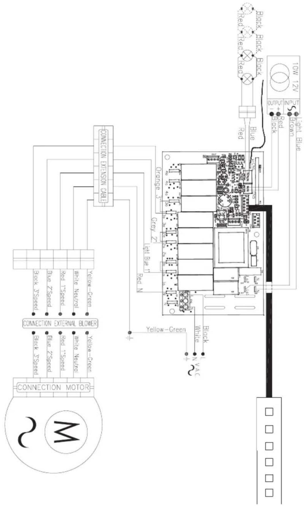
REMOTE BLOWER CIRCUIT DIAGRAM
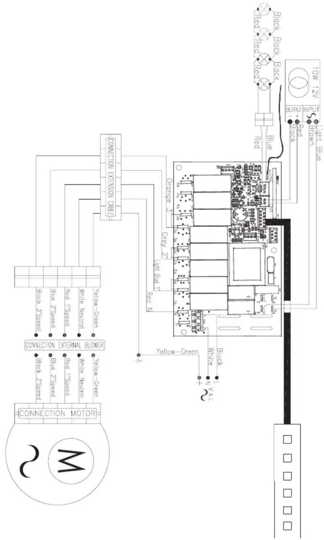
text_image
10W 12V OUTPUT + Red Blue Black Black Blue Red Light Blue Brown ONION EXTENSION CABLE Orange 3" Credy 2" Light Blue 1" Red N Yellow-Green White N VAC Yellow-Green White N CONNECTION MOTA CONNECTION EXTERNAL BLOWER CONNECTION MOTOR Black 3"Speed Blue 2"Speed Red 1"Speed White Neutral Yellow-Green Black 5"Speed Black 5"Speed CONNECTION MOTORList of Parts and Accessories
| DESCRIPTION HOOD PART# | ||
| REPLACEMENT PARTS | ||
| LED Light 1.3W (each) | DVL | Z0B0051 |
| OPTIONAL ACCESSORIES | ||
| Recirculating Kit | DVL | ZRC-00VL |
| Replacement Charcoal Filters | DVL | Z0F-C010 |
| Duct Cover Extension | DVL | Z1C-00VL |
| Remote Control | DVL | 14000010 |
| Internal Blower, 290 CFM | DVL | CBI-290A |
| Internal Blower, 600 CFM | DVL | CBI-600A |
| External Blower, 1000 CFM | DVL | CBE-1000 |
| In-Line Blower, 1000 CFM | DVL | PBN-1000A |
To order parts, visit us online at http://store.zephyronline.com or call us at 1.888.880.8368
| UL References | |
| LED Light 1.3W (each) | SPK8148 |
| Recirculating Kit | KIT0I0523 |
| Replacement Charcoal Filters | ACK00061 |
| Duct Cover Extension Inox | KIT0I0524 |
ZEPHYR Limited Warranty
TO OBTAIN SERVICE UNDER WARRANTY OR FOR ANY SERVICE RELATED QUESTIONS: United States Customers please call: 1-888-880-8368 or contact us at: zephyronline.com/contact Canada Customers please call: 1-800-361-0799 or Email: service@distinctive-online.com
Zephyr Ventilation, LLC (referred to herein as "we" or "us") warrants to the original consumer purchaser (referred to herein as "you" or "your") of Zephyr products (the "Products") that such Products will be free from defects in materials or workmanship as follows:
Two Year Limited Warranty for Parts: For two years from the date of your original purchase of the Products, we will provide, free of charge, Products or parts (including LED light bulbs, if applicable) to replace those that failed due to manufacturing defects subject to the exclusions and limitations below. We may choose, in our sole discretion, to repair or replace parts before we elect to replace the Products.
One Year Limited Warranty for Labor: For one year from the date of your original purchase of the Products, we will provide, free of charge, the labor cost associated with repairing the Products or parts to replace those that failed due to manufacturing defects subject to the exclusions and limitations below. After the first year from the date of your original purchase, you are responsible for all labor costs associated with this warranty.
Warranty Exclusions: This warranty covers only repair or replacement, at our option, of defective Products or parts and does not cover any other costs related to the Products including but not limited to: (a) normal maintenance and service required for the Products and consumable parts such as fluorescent, incandescent or halogen light bulbs, mesh and charcoal filters and fuses; (b) any Products or parts which have been subject to freight damage, misuse, negligence, accident, faulty installation or installation contrary to recommended installation instructions, improper maintenance or repair (other than by us); (c) commercial or government use of the Products or use otherwise inconsistent with its intended purpose; (d) natural wear of the finish of the Products or wear caused by improper maintenance, use of corrosive and abrasive cleaning products, pads, and oven cleaner products; (e) chips, dents or cracks caused by abuse or misuse of the Products; (f) service trips to your home to teach you how to use the Products; (g) damage to the Products caused by accident, fire, floods, acts of God; or (h) Custom installations or alterations that impact serviceability of the Products. If you are outside our service area, additional charges may apply for shipping costs for warranty repair at our designated service locations and for the travel cost to have a service technician come to your home to repair, remove or reinstall the Products. After the first year from the date of your original purchase, you are also responsible for all labor costs associated with this warranty. All Products must be installed by a qualified professional installer to be eligible for warranty repairs or service.
Limitations of Warranty. OUR OBLIGATION TO REPAIR OR REPLACE, AT OUR OPTION, SHALL BE YOUR SOLE AND EXCLUSIVE REMEDY UNDER THIS WARRANTY. WE SHALL NOT BE LIABLE FOR INCIDENTAL, CONSEQUENTIAL OR SPECIAL DAMAGES ARISING OUT OF OR IN CONNECTION WITH THE USE OR PERFORMANCE OF THE PRODUCTS. THE EXPRESS WARRANTIES IN THE PRECEDING SECTION ARE EXCLUSIVE AND IN LIEU OF ALL OTHER EXPRESS WARRANTIES. WE HEREBY DISCLAIM AND EXCLUDE ALL OTHER EXPRESS WARRANTIES FOR THE PRODUCTS, AND DISCLAIM AND EXCLUDE ALL WARRANTIES IMPLIED BY LAW, INCLUDING THOSE OF MERCHANTABILITY AND FITNESS FOR A PARTICULAR PURPOSE.
Some states or provinces do not allow limitations on the duration of an implied warranty or the exclusion or limitation of incidental or consequential damages, so the above limitations or exclusions may not apply to you. To the extent that applicable law prohibits the exclusion of implied warranties, the duration of any applicable implied warranty is limited to the same two-year and one-year periods described above if permitted by applicable law. Any oral or written description of the Products is for the sole purpose of identifying the Products and shall not be construed as an express warranty. Prior to using, implementing or permitting use of the Products, you shall determine the suitability of the Products for the intended use, and you shall assume all risk and liability whatsoever in connection with such determination. We reserve the right to use functionally equivalent refurbished or reconditioned parts or Products as warranty replacements or as part of warranty service. This warranty is not transferable from the original purchaser and only applies to the consumer residence where the Product was originally installed located in the United States and Canada. This warranty is not extended to resellers.
To Obtain Service Under Limited Warranty: To qualify for warranty service, you must: (a) notify us at the address or telephone number stated below within 60 days of the discovery of the defect; (b) give the model number and serial number; and (c) describe the nature of any defect in the Product or part. At the time of the request for warranty service, you must present evidence of your proof of purchase and proof of the original purchase date. If we determine that the warranty exclusions listed above apply or if you fail to provide the necessary documentation to obtain service, you will be responsible for all shipping, travel, labor and other costs related to the services. This warranty is not extended or restarted upon warranty repair or replacements.
Please check our website for any additional Product information, www.zephyronline.com.
Zephyr, 2277 Harbor Bay Parkway, Alameda, CA 94502
VISTA ISLAND
DVL-E36ASSX
DVL-E42ASSX
natural_image
Isometric technical drawing of a ceiling structure with mounting brackets and ventilation slots (no text or symbols)
Instructions De Securite 2/5
* National Fire Protection Association Batterymarch Park, Quincy, Massachusetts 02269
** CSA International 8501 East Pleasant Valley Road, Cleveland, Ohio 44131-5575
Instructions De Securite 5/5
Specifications Techniques
text_image
11-1/4" 2-1/8" 23-5/8"text_image
9-1/4" 7-1/2"text_image
Technical diagram of a mechanical device with labeled components and directional arrows indicating motion or assembly.natural_image
Technical diagram of a mechanical assembly with labeled component (2), showing internal components and a downward arrow indicating motion or force (no text or symbols present)text_image
Diagram of an electronic device with labeled components and wiring, showing a connector with pins 1, 2, 3 and a numbered part (4)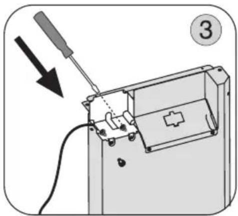
natural_image
Diagram of a soldering iron on an electronic device with a screwdriver inserted (no text or symbols)natural_image
Illustration of a device being connected to an air conditioner unit, showing internal components and wiring (no text or symbols)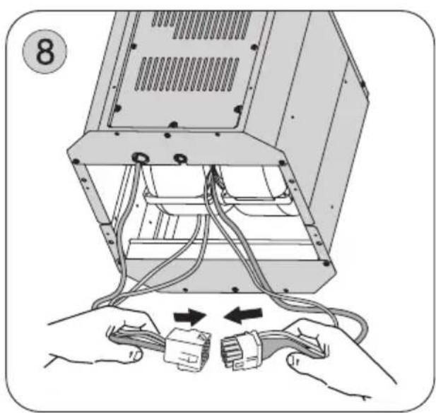
natural_image
Illustration of hands connecting to a computer tower with cable and connector (no text or symbols)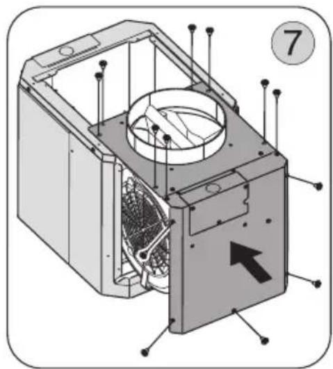
natural_image
Technical diagram of an internal device with labeled components and directional arrow (no text or symbols beyond labels)natural_image
Illustration of a mechanical assembly with hands using a tool to adjust components (no text or symbols present)natural_image
Technical diagram of a mechanical assembly with a tool inserted, showing internal components and alignment lines (no text or symbols)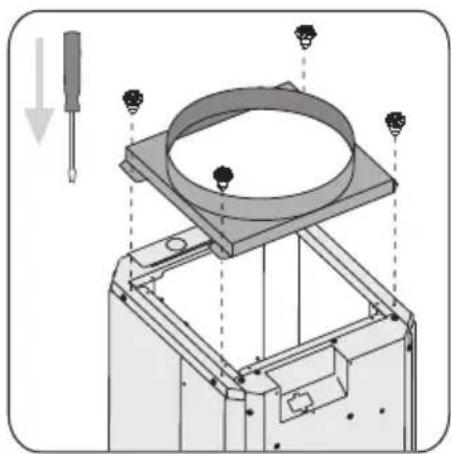
natural_image
Technical diagram of a mechanical assembly with labeled components and directional arrows (no text or symbols)natural_image
Technical diagram of a 3D printer or scanner component with an inset close-up showing internal components (no text or symbols)natural_image
Mechanical assembly diagram showing a rotating component mounted on a base plate, with no visible text or symbols.natural_image
Illustration of hands holding a device with circular components and a magnified inset showing internal structures (no text or symbols)text_image
X C 4 - 7/16" 24" B X = C - (4 - 7/16" + 24" + B)Ildoityavoirunminimumde
natural_image
Technical illustration of a mechanical housing component with mounting holes and internal compartments (no text or symbols)text_image
Diagram illustrating a mechanical assembly or lifting process with labeled components and directional arrows indicating motion.natural_image
Diagram of a mechanical lifting or assembly process showing two stages of frame structure with hands holding parts (no text or symbols)natural_image
Technical diagram of a multi-level mechanical assembly with tool application, showing internal components and alignment (no text or symbols)natural_image
Technical diagram of a mechanical assembly with screws and a numbered label (5), showing internal components without any readable text or symbols.text_image
Diagram illustrating a mechanical assembly or repair process with labeled steps and tool positions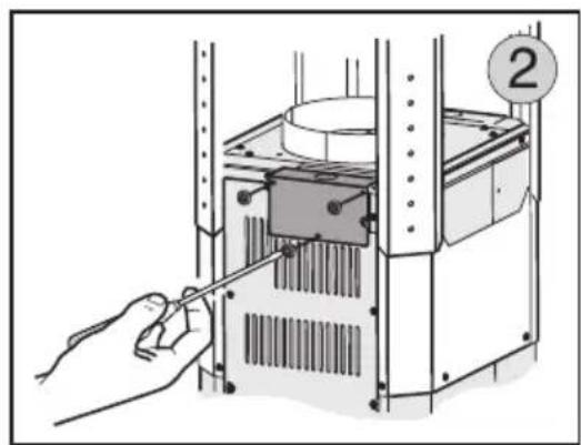
natural_image
Illustration of a hand using a tool to adjust or install a mechanical component, no text or symbols present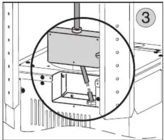
natural_image
Technical diagram of a mechanical assembly with a magnified inset showing internal components (no text or symbols)natural_image
Illustration of a hand pressing down a cylindrical component into a machine (no text or symbols visible)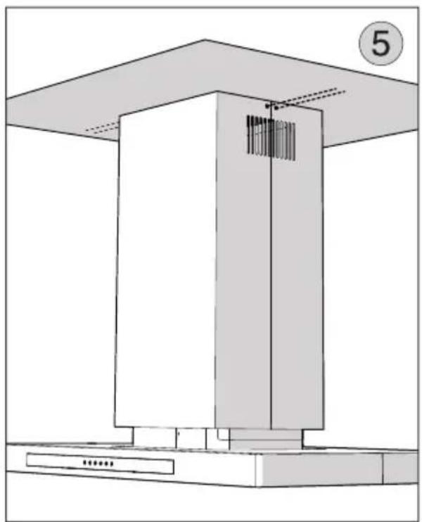
natural_image
Architectural diagram of a modern kitchen or ventilation unit with a cabinet and base, no visible text or symbols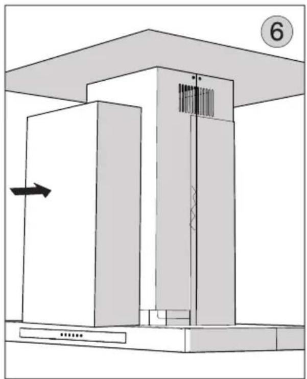
natural_image
Architectural diagram showing a cabinet with an elevator and a door, no text or symbols presentContrôle tactile
text_image
A B C D E Ftext_image
Hand pointing at a control panel with icons for lightbulb, clock, alarm, pause, and stop buttons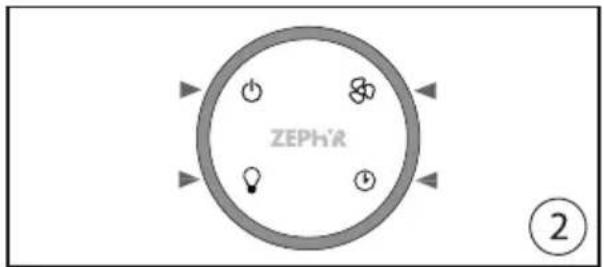
text_image
ZEPHR ②REPLACEMENT DES PILES:
natural_image
Illustration of a hand pressing down on a circular object with a knob, labeled with number 3 (no text or symbols on the object itself)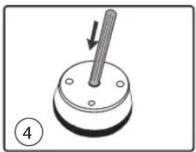
natural_image
Mechanical component with a rod inserted into a circular base, labeled with number 4 (no text or symbols on the object itself)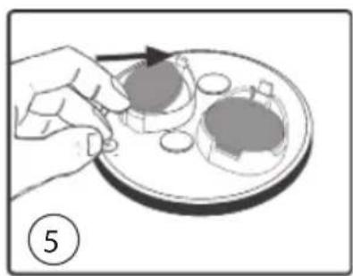
natural_image
Illustration of a hand placing a small object onto a plate with a circular inset, no text or symbols presentEntretien
text_image
Yellow-Green Red Capacitors White Neutral Blue 3"Speed Grey 1"Speed Yellow Red Blue White Grey Black Yellow-Green CONNECTION BLOWER Orange 3" Grey 2" Light Blue 1" Red N Yellow-Green White N V AC Black Red Blue Black Red Red Output + Red Brown TOW 12V OUTPUT OUTPUT + Black Light BlueSchéma de câblage
SCHÉMA DU CIRCUIT DE MOTEUR EXTERIEUR
text_image
CONNECTION EXTENSION CABLE Black 3*Speed Blue 2*Speed Red 1*Speed White Neutral Yellow-Green CONNECTION EXTERNAL BLOWER Black 3*Speed Blue 2*Speed Red 1*Speed White Neutral YELLOW-Green CONNECTION MOTOR 2 M Black Black Red Black Blue Blue Orange 3* Grey 2* Light Blue 1* Red N Yellow-Green White VAC N VAC OUTPUT + Red 1 Black 1CW 12V NPS Light Blue BrownZephyr, 2277 Harbor Bay Parkway, Alameda, CA 94502
JAN21.0201
PRODUCT REGISTRATION
Congratulations on your Zephyr range hood purchase! Please take a moment to register your new range hood at www.zephyronline.com/registration
IT'S IMPORTANT
Prompt registration helps in more ways than one.
- Ensures warranty coverage should you need service.
- Ownership verification for insurance purposes.
- Notification of product changes or recalls.

text_image
STOPZephyr Ventilation | 2277 Harbor Bay Pkwy. | Alameda, CA 94502 | 1.888.880.8368