
TP-RO 18 Li BL - Milling machine EINHELL - Free user manual and instructions
Find the device manual for free TP-RO 18 Li BL EINHELL in PDF.

User questions about TP-RO 18 Li BL EINHELL
0 question about this device. Answer the ones you know or ask your own.
Ask a new question about this device
Download the instructions for your Milling machine in PDF format for free! Find your manual TP-RO 18 Li BL - EINHELL and take your electronic device back in hand. On this page are published all the documents necessary for the use of your device. TP-RO 18 Li BL by EINHELL.
USER MANUAL TP-RO 18 Li BL EINHELL
GB Original operating instructions Cordless router/palm router
natural_image
Close-up of a mechanical assembly with a 3D printing machine and a labeled component (no readable text or symbols)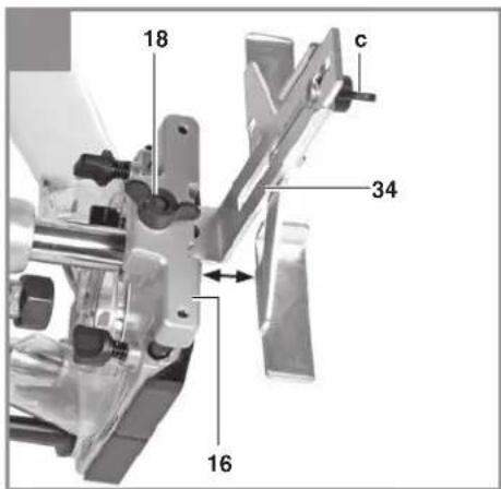
natural_image
Close-up of a mechanical component with a central bore and labeled part '29' (no other text or symbols visible)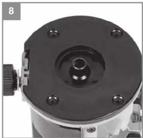
natural_image
Close-up of a mechanical component with a central bore and mounting holes (no visible text or symbols)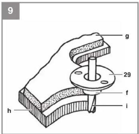
natural_image
Close-up of a mechanical component with labeled parts (no readable text or symbols)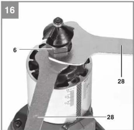
D
Gefahr!
When using the equipment, a few safety precautions must be observed to avoid injuries and damage. Please read the complete operating instructions and safety regulations with due care. Keep this manual in a safe place, so that the information is available at all times. If you give the equipment to any other person, hand over these operating instructions and safety regulations as well. We cannot accept any liability for damage or accidents which arise due to a failure to follow these instructions and the safety instructions.
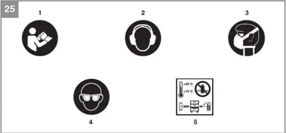
Explanation of the symbols used (see Fig. 25)
- Danger! - Read the operating instructions to reduce the risk of injury.
- Caution! Wear ear-muffs. The impact of noise can cause damage to hearing.
- Caution! Wear a breathing mask. Dust which is injurious to health can be generated when working on wood and other materials. Never use the device to work on any materials containing asbestos!
- Caution! Wear safety goggles. Sparks generated during working or splinters, chips and dust emitted by the device can cause loss of sight.
- Store the batteries only in dry rooms with an ambient temperature of +10°C to +40°C. Place only fully charged batteries in storage (charged at least 40%).
1. Safety regulations
The corresponding safety information can be found in the enclosed booklet.
WARNING!
Read all safety warnings, instructions, illustrations and specifications provided with this power tool. Failure to follow all instructions listed below may result in electric shock, fi re and/or serious injury.
Save all warnings and instructions for future reference.
2. Layout and items supplied
2.1 Layout (Fig. 1+2)
- Cordless routing unit
- Unlock button
- On/Off switch
- Speed control
- Spindle lock
- Clamp nut
- Handles
- Precision adjustment device
- Scale
- Display
- Lock nutf
- Depth setting
- Limit stop
- Depth stop
- Safety guard
- Holder for parallel stop
- Fastening screws for holder for parallel stop
- Fastening screws for parallel stop
- Clamp lever
- Extractor adapter
- Fastening screw for extractor adapter
- Fastening screw for routing unit
- Fastening screw for depth adjuster
- Height adjuster
- Fastening screw for routing guide
- Extractor adapter
- Countersunk head screw for extractor adapter
- Open-ended wrench
- Copy sleeve
- Clamp 6mm
- Clamp 8mm
- Routing guide
- Compass point
- Parallel stop
- Router insert
- Palm router insert
- LED lamp
- Scale
2.2 Items supplied
Please check that the article is complete as specified in the scope of delivery. If parts are missing, please contact our service center or the sales outlet where you made your purchase at the latest within 5 working days after purchasing the product and upon presentation of a valid bill of purchase. Also, refer to the warranty table in the service information at the end of the operating instructions.
GB
- Open the packaging and take out the equipment with care.
- Remove the packaging material and any packaging and/or transportation braces (if available).
- Check to see if all items are supplied.
- Inspect the equipment and accessories for transport damage.
- If possible, please keep the packaging until the end of the guarantee period.
Danger!
The equipment and packaging material are not toys. Do not let children play with plastic bags, foils or small parts. There is a danger of swallowing or suff ocating!
- Cordless routing unit
- Router insert
• Palm router insert - Extractor adapter (2x)
- Compass point
• Clamping sleeve 6+8mm - Routing guide
- Parallel stop
• Open-ended wrench (2x) - Copy sleeve
Safety guard
• Original operating instructions - Safetyinstructions
3. Proper use
This cordless router/palm router is designed primarily for the machining of wood and plastic. Its uses include the cutting out of knots, the cutting of slots, the forming of recesses, the copying of curves and lettering, fl ush-trimming, etc. This cordless router/palm router is not allowed to be used for the machining of metal, stone, etc.
The equipment is to be used only for its prescribed purpose. Any other use is deemed to be a case of misuse. The user / operator and not the manufacturer will be liable for any damage or injuries of any kind caused as a result of this.
Please note that our equipment has not been designed for use in commercial, trade or industrial applications. Our warranty will be voided if the machine is used in commercial, trade or industrial businesses or for equivalent purposes.
4. Technical data
Motor power supply: 18 V
Idling speed: 10,000 - 30,000 min ^1
Stroke height: 40 mm (routing depth)
Clamp: 8 mm and 6 mm
For routing cutters max.: 30 mm
Weight Cordless router: 2.4 kg
Weight Cordless palm router: 1.3 kg
Danger!
Sound and vibration
Sound and vibration values were measured in accordance with EN 62841.
L_pA sound pressure level 80.4 dB(A)
K_pA uncertainty 3 dB
L_WA sound power level 91.4 dB(A)
K_WA uncertainty ....3 dB
Wear ear-muff s.
The impact of noise can cause damage to hearing.
Total vibration values (vector sum of three directions) determined in accordance with EN 62841.
Handle
Vibration emission value a_n = 1.983m / s^2
K uncertainty = 1.5 m/s ^4
The stated vibration emission levels and stated noise emission values were measured in accordance with a set of standardized criteria and can be used to compare one power tool with another.
The stated vibration emission levels and stated noise emission values can also be used to make an initial assessment of exposure.
Warning:
The vibration and noise emission levels may vary from the level specified during actual use, depending on the way in which the power tool is used, especially the type of workpiece it is used for.
Keep the noise emissions and vibrations to a minimum.
- Only use appliances which are in perfect working order.
• Service and clean the appliance regularly.
• Adapt your working style to suit the appliance.
GB
• Do not overload the appliance.
- Have the appliance serviced whenever necessary.
- Switch the appliance off when it is not in use.
Limit the operating time!
All stages of the operating cycle must be considered (for example, times in which the electric tools are switched off and times in which the tool is switched on but operates without load).
Caution!
Residual risks
Even if you use this electric power tool in accordance with instructions, certain residual risks cannot be rules out. The following hazards may arise in connection with the equipment's construction and layout:
- Lung damage if no suitable protective dust mask is used.
- Damage to hearing if no suitable ear protection is used.
- Health damage caused by hand-arm vibrations if the equipment is used over a prolonged period or is not properly guided and maintained.
5. Before starting the equipment
Warning!
Always pull out the battery before making adjustments to the equipment.
All covers and safety devices must be properly fitted before the equipment is switched on.
5.1 Fitting the extraction socket
(Fig. 1.2+1.3/Item 20/26)
Caution! For health and safety reasons it is imperative that you use a dust extractor.
- Connect your cordless tool to a domestic vacuum cleaner or a dust extractor using the extraction socket (20/26). This will ensure optimum dust extraction from the workpiece. The benefits are that you will protect both the equipment and your own health. Your work area will also be cleaner and safer.
- Dust created when working may be dangerous. Refer to the section entitled “Safety instructions”.
- The vacuum cleaner you use for the vacuum extraction must be suitable for the material you are machining. Use a special vacuum
cleaner if you are handling harmful materials.
Cordless router (Fig. 1.3/Item 20)
- Use the retaining hook to attach the extractor adapter (20) to the routing shoe (a) and secure it with the fastening screw for the extractor adapter (21).
- The extractor adapter (20) can be connected to extractor units (vacuum cleaners) with a suction hose.
- The internal diameter of the extractor adapter is 36 mm. Now fit a suction hose of matching size to the extractor adapter.
Cordless palm router (Fig. 1.2/Item 26)
- Secure the extractor adapter (26) to the palm router insert (36) using the countersunk screw (27).
- The extractor adapter can be connected to extractor units (vacuum cleaners) with a suction hose.
- The internal diameter of the extractor adapter is 36 mm. Now fit a suction hose of matching size to the extractor adapter.
5.2 Fitting the safety guard
(Only for the cordless router!) (Fig. 3/Item 15)
Fit the safety guard (15) as shown in Fig. 1. To remove the safety guard (15), pull it to the front.
5.3 Fitting the parallel stop (Fig. 4/ Item 34)
Cordless router
- Insert the holder for the parallel stop (16) in the guides provided on the routing shoe (a) as shown in Fig. 1.1 and secure with the two fastening screws for the holder for the parallel stop (17).
- Undo the fastening screw for the parallel stop (18) on the holder for the parallel stop (16).
- Insert the parallel stop (34) in the holder for the parallel stop (16) as shown in Fig. 4.1 and retighten the fastening screw for the parallel stop (18).
- Set the parallel stop (34) to the required dimension and secure it in place with the wing screw (c).
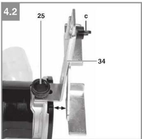
Cordless palm router
- Undo the fastening screw for the routing guide (25).
- Insert the parallel stop (34) in the holder for the routing guide (25) as shown in Fig. 4.2
GB
and retighten the fastening screw for the routing guide (25).
- Set the parallel stop (34) to the required dimension and secure it in place with the wing screw (c).
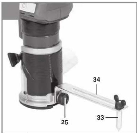
5.4 Fitting the compass point (Fig. 5/Item 33)
- You can cut circular areas using the compass point (33).
• To do so, undo the wing nut (c) and remove the front section of the parallel stop (34). - Screw-fit the compass point (33) on the parallel stop (34) as shown in Fig. 5. Now fit the parallel stop (34) together with the compass point (33) on the router.
- The procedure for fitting is the same as described in section 5.3 except that the parallel stop (34) must be turned through 180^ so that the compass point (33) points downwards (Fig. 5).
- Set the required radius between the compass point (33) and the cutter.
- Position the compass point (33) in the center of the circle you wish to cut.
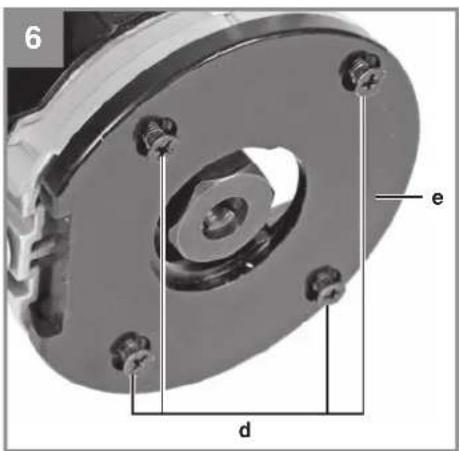
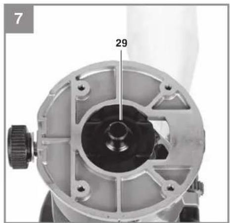
5.5 Fitting and using the copy sleeve (Only for the palm router!) (Fig. 6-9/Item 29)
- Remove the four recessed head screws (d) from the bottom of the palm router insert and take off the cover (e) (Fig. 6).
• Insert the copy sleeve (29) as shown in Fig. 7. - Refit the cover (e) using the four recessed head screws (d).
- The copy sleeve (29) will be guided along the template (g) by the guide ring (f).
- To obtain an exact copy the workpiece (h) must be larger by the difference between the “external edge of the guide ring” and the “external edge of the cutter” (i).
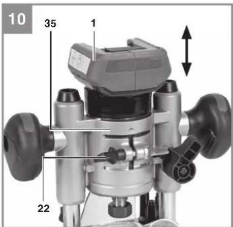
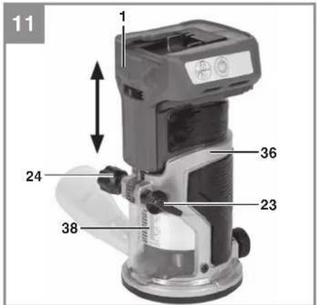
5.6 Fitting/removing the cordless routing unit (Fig. 10-11)
Warning! Remove the battery.
Cordless router
- To insert the cordless routing unit (1) in the router insert (35), first undo the fastening screw for the routing unit (22) and then insert the cordless routing unit (1).
- Now you must retighten the fastening screw for the routing unit (22).
Cordless palm router
- To insert the cordless routing unit (1) in the palm router insert (36), first undo the fastening screw for the depth adjuster (23) and then insert the cordless routing unit (1).
- Then use the height adjuster (24) and the scale (38) to set the required cutting depth.
• Finally retighten the fastening screw for the depth adjuster (23).
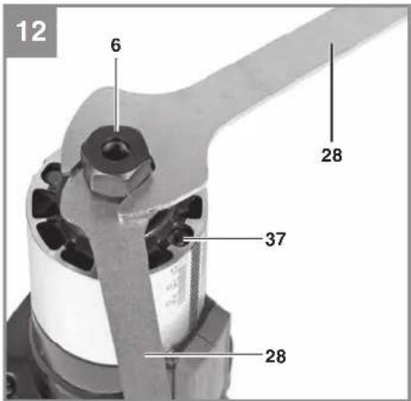
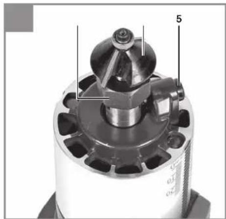
5.7 Fitting/removing the cutting tool (Fig. 12-16)
Warning! Remove the battery.
Caution! When you have fi nished working with the router, the cutting tool will stay very hot for a relatively long time! Caution! Cutters are very sharp. Wear protective gloves at all times when handling cutting tools.
- To make it easier to change the cutter, remove the cordless routing unit (1) from the respective insert as described in section 5.6
- Cutters with a shaft diameter of 6 mm and 8 mm can be used in the cordless router/palm router. Most cutters are available in both sizes.
- You can use cutters made of the following materials:
- HSS - suitable for cutting softwood
- TCT - suitable for cutting hardwood, particle board and plastic
- Select the appropriate cutting tool for the job in hand.
- When using the cutters for the first time: Remove the plastic packaging from the cutter heads.
- Clean the nut, clamp and shaft of the cutter before fitting it.
- Undo the clamp nut (6) using the two open-ended wrenches (28).
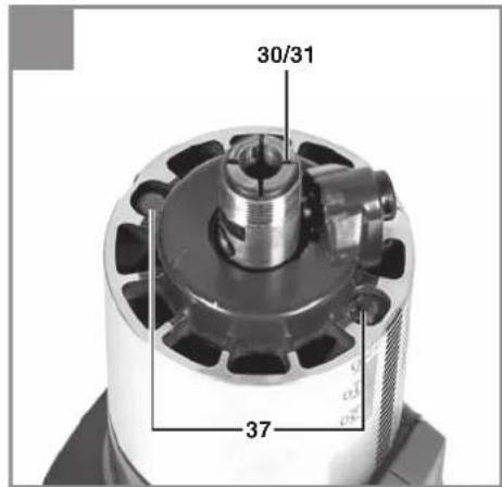
- If a cutter is already fitted in the clamp (30/31), remove it.
- Select the appropriate cutting tool for the job in hand.
- Select the appropriate clamp (30/31) for the cutter (i) you want to use.
• Now insert the clamp (30/31) in the cutting spindle (Fig. 13).
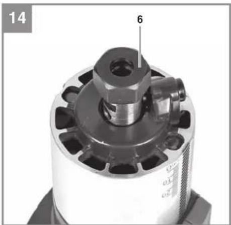
• Refit the clamp nut (6) (Fig. 14).
• Guide the cutter shaft into the clamp (Fig. 15). - While holding the spindle lock (5) in pressed position, screw the clamp nut (6) hand-tight (Fig. 15).
GB
- Notice! The spindle lock is not allowed to be used for tightening with the open-ended wrench (28)!
- Tighten the clamp nut (6) using the two open-ended wrenches (28).
- The cutter must be inserted into the clamp (30/31) by at least 20mm.
- Before you use the equipment, check that the cutting tool is secure and runs true.
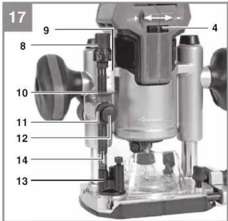
5.8 Adjusting the end stops (Fig. 17/Item 13) The end stops (13) can be adjusted in height according to requirements. To do so, use a hex key to turn the screw on the end stop (13) to the required stop height.
Warning! Remove the setting and assembly tools again before starting the machine.
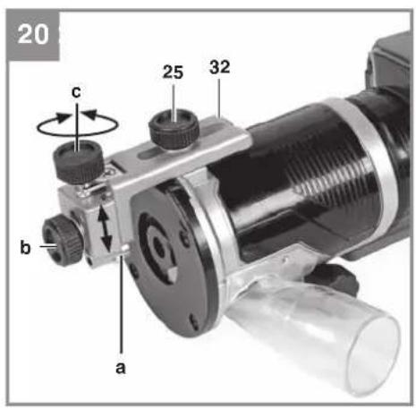
5.9 Fitting/removing the routing guide (Fig. 20/Item 32)
- Undo the fastening screw for the routing guide (25), insert the routing guide (32) as shown in Fig. 20, and establish the appropriate height.
- Retighten the fastening screw for the routing guide (25).
- Now use the adjustment screw (c) to set the required lateral feed and use the retaining screw (b) to secure the routing guide.
6. Operation
- Never use a low-quality or damaged cutter. Use only cutting tools with a shaft diameter of 6 mm or 8 mm. The cutters must also be designed for the respective idling speed.
- Secure the workpiece so that it cannot be thrown through the air as you work on it. Use clamps or a vise.
• Never cut over metal parts, screws, nails etc.
6.1 On/Off switch (Fig. 1/Item 3) For safety reasons, the cordless router/palm router is equipped with a safety lock-off.
- To switch on, press the unlock/lock button (2). The LED lamp (37) will begin to shine by way of confirmation.
- Now press the On/Off switch (3) within the next 10 seconds.
- If the On/Off switch is not pressed for longer than 10 seconds, the LED lamp (37) will go out and the equipment cannot be switched on.
- To switch off, press either the unlock/lock button (2) or the On/Off switch (3).
6.2 Speed control (Fig. 17/Item 4)
The most suitable speed depends on the material you want to cut and on the diameter of the cutter. Use the speed control switch (4) to select a speed between 10,000 and 30,000 min ^-1 . You can choose from 6 different switch positions.
The speeds in the various switch positions are as follows:
Switch position 1: approx. 10,000 min ^1 (minimum speed)
Switch position 2: approx. 14,000 min ^1
Switch position 3: approx. 19,000 min ^1
Switch position 4: approx. 22,000 min ^1
Switch position 5: approx. 25,000 min ^1
Switch position 6: approx. 30,000 min ^1
(maximum speed)
To increase the speed:
Move the speed controller (4) in the plus direction.
To decrease the speed:
Move the speed controller (4) in the minus direction.
6.3 Adjusting the routing depth
(Only for the cordless router!) (Fig. 17)
- Place the machine on the workpiece.
- Undo the lock nut (11) and the clamp lever (19).
- Slowly move the machine downwards and press the depth adjuster (12) until the cutter makes contact with the workpiece.
• Tighten the clamp lever (19).
- Set the precision adjustment device (8) accordingly to 0.
- Set the end stop (13) so that the depth stop (14) lies above the lowest set end stop (13).
- Press the depth adjuster (12) to lower the depth stop (14) until it touches the end stop (13). Then tighten the lock nut (11) and release the clamp lever (19).
- Set the pointer (10) to the zero point on the scale (9).
- Undo the lock nut (11). Push up the depth stop (14) until the pointer (10) shows the required routing depth on the scale (9). Retighten the lock nut (11).
- Test the setting by performing a test cut on a piece of scrap material.
- Now the routing depth can be finely adjusted. Begin by turning the precision adjustment
GB
device (8) to the required dimension.
Turn the precise adjustment device (8) counterclockwise:
The routing depth is raised
Turn the precision adjustment device (8) clockwise:
The routing depth is lowered
Turning the precision adjustment device (8) by one increment is equivalent to changing the routing depth by 0.1mm; one full turn is equivalent to 1mm.
6.4 Routing
Cordless router
- To avoid damage to the router, make sure there are no foreign objects attached to the workpiece.
- Hold both of the router's handles (7).
- Place the cordless router on the workpiece.
- Set the routing depth as explained in section 6.3.
- Select the speed as explained in section 6.2 and switch on the equipment (see section 6.1)
- Test the equipment's settings on a scrap piece of material.
- Let the equipment reach full speed. Only then should you lower the cutter to its working height and lock the equipment with the clamp lever (19).
Cordless palm router
- To avoid damage to the router, make sure there are no foreign objects attached to the workpiece.
- Hold the router's handle.
- Place the cordless palm router on the workpiece.
- Set the routing depth as explained in section 5.6.
- Select the speed as explained in section 6.2 and switch on the equipment (see section 6.1)
- Test the equipment's settings on a scrap piece of material.
• Let the equipment reach full speed.
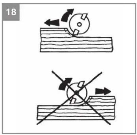
Cutting direction: The cutting tool turns clockwise. To avoid accidents you must always cut against the direction in which the tool turns (Fig. 18).
Feed speed: It is very important to machine the workpiece at the correct feed speed. We recommend that before you machine the actual workpiece, you carry out several trial cuts on a scrapped piece of the same material. This is the easiest way to find the best working speed for the workpiece.
Feed speed too low:
The cutter might overheat. If you are cutting in-fl ammable material such as wood, the workpiece might ignite.
Feed speed too high:
The cutter might become damaged. Cutting quality: Rough and uneven.
Allow the cutter to come to a complete standstill before removing the workpiece or putting down the router.
6.5 Step-by-step routing
Step-by-step routing makes sense when processing hard material and performing deep cuts.
- Adjust the end stops as explained in section 5.8.
- To carry out a routing job in several steps you must then set the routing depth as explained in section 6.3 before turning the end stop (13) so that the depth stop (14) lies above the highest end stop (13).
- Now perform a cut in this setting. When the first cut is completed, set the end stop (13) so that the depth stop (14) lies above the middle end stop. Now perform a cut in this setting as well.
- Finally, set the lowest end stop and complete the cutting.
6.6 Cutting circles with the compass point (33)
Proceed as follows to cut circles around a center-point:
• Fit and adjust the compass point (33) as explained in section 5.4.
- Place the compass point (33) on the center-point of the circle you want to cut and press it in place.
• Perform the cut as described in section 6.4.
6.7 Making cuts with the parallel stop (34)
Proceed as follows to cut along a straight outer edge of a workpiece:
• Fit the parallel stop (34) as explained in section 5.3.
• Move the parallel stop (34) along the outer
GB
edge of the workpiece.
• Perform the cut as explained in section 6.4.
6.8 Making cuts freehand
The cordless router/palm router can also be used without any guides. You can use it freehand on creative jobs such as the production of lettering.
• Use a very flat cutter setting for this purpose!
- Check the direction in which the cutter is turning while you machine the workpiece (Fig. 18).
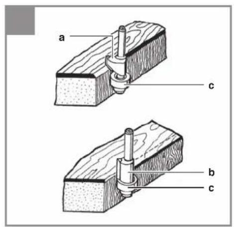
6.9 Cutting shapes and edges (Fig. 19)
- Special cutters with a guide ring can be used for cutting shapes (a) and edges (b).
• Fit the cutter. - Carefully move the machine against the workpiece.
• Using gentle pressure, move the guide journal or ball bearing (c) along the workpiece.
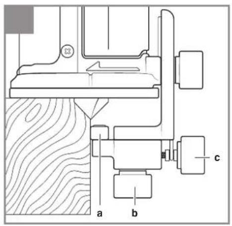
Cordless palm router
With the help of the routing guide (32) you can also perform edge cuts.
• Fit the routing guide (32) as explained in Fig. 5.9.
- Place the cordless palm router on the workpiece and adjust the height of the routing guide (32) so that the ball bearing (a) lies underneath the cutter.
- Now undo the fastening screw (b) and then use the adjustment screw (c) to set the lateral feed of the cutter.
• Retighten the fastening screw (b).
Warning:
For deep cuts, carry out the work in several steps according to the material in question. Hold the equipment in two hands during all cutting work.
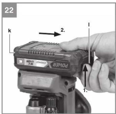
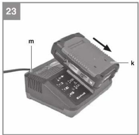
6.10 Charging the LI battery pack (Fig. 22-23)
- Remove the battery pack (k) from the handle, pressing the pushlock buttons (l) downwards to do so.
- Check that your mains voltage is the same as that marked on the rating plate of the battery charger. Insert the power plug of the charger (6) into the mains socket outlet. The green LED will then begin to flash.
- Push the battery pack onto the battery charger.
In section "Charger indicator" you will find a table with an explanation of the LED indicator on the charger.
If the battery pack fails to become charged, please check
• whether there is voltage at the socket-outlet
- whether there is proper contact at the charging contacts on the charger.
If the battery still fails to become charged, please return
• thecharger
• the battery pack
to our Customer Service Department.
To ensure that items are properly packaged and delivered when you send them to us, please contact our customer service or the point of sale at which the equipment was purchased.
When shipping or disposing of batteries and cordless tools, always ensure that they are packed individually in plastic bags to prevent short circuits and fi res.
To ensure that the battery pack provides long service, you should take care to recharge it promptly. You must recharge the battery pack when you notice that the performance of the device drops. Never allow the battery pack to become fully discharged. This will cause it to develop a defect.
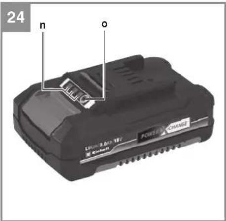
6.11 Battery capacity indicator
(Fig. 24/Item n)
Press the battery capacity indicator switch (o). The battery capacity indicator (n) shows the charge status of the battery using 3 LEDs.
All 3 LEDs are lit:
The battery is fully charged.
2 or 1 LED(s) are lit:
The battery has an adequate remaining charge.
1 LED fl ashes:
The battery is empty, recharge the battery.
All LEDs blink:
The battery temperature is too low. Remove the battery from the equipment, keep it at room temperature for one day. If the fault reoccurs, this means that the rechargeable battery has undergone exhaustive discharge and is defective. Remove
GB
the battery from the equipment. Never use or charge a defective battery.
7. Cleaning, maintenance and ordering of spare parts
Hazard!
Always pull out the battery pack before starting any cleaning work.
7.1 Cleaning
- Keep all safety devices, air vents and the motor housing free of dirt and dust as far as possible. Wipe the equipment with a clean cloth or blow it with compressed air at low pressure.
- We recommend that you clean the device immediately each time you have finished using it.
- Clean the equipment regularly with a moist cloth and some soft soap. Do not use cleaning agents or solvents; these could attack the plastic parts of the equipment. Ensure that no water can seep into the device. The ingress of water into an electric tool increases the risk of an electric shock.
7.2 Maintenance
There are no parts inside the equipment which require additional maintenance.
7.3 Ordering replacement parts:
Please quote the following data when ordering replacement parts:
• Type of machine
• Article number of the machine
• Identification number of the machine
• Replacement part number of the part required
For our latest prices and information please go to www.Einhell-Service.com
8. Disposal and recycling
The equipment is supplied in packaging to prevent it from being damaged in transit. The raw materials in this packaging can be reused or recycled. The equipment and its accessories are made of various types of material, such as metal and plastic. Never place defective equipment in your household refuse. The equipment should be taken to a suitable collection center for proper disposal. If you do not know the whereabouts of such a collection point, you should ask in your local council offices.
9. Storage
Store the equipment and accessories in a dark and dry place at above freezing temperature. The ideal storage temperature is between 5 and 30 °C. Store the electric tool in its original packaging.
10. Charger indicator
| Indicator status Explanations and actions | ||
| Red LED Green LED | ||
| Off | Flashing | Ready for useThe charger is connected to the mains and is ready for use; there is no battery pack in the charger |
| On Off Charging | The charger is charging the battery pack in quick charge mode. The charging times are shown directly on the charger.Important! The actual charging times may vary slightly from the stated charging times depending on the existing battery charge. | |
| Off | On | The battery is charged and ready for use. (READY TO GO)The unit then changes over to gentle charging mode until the battery is fully charged.To do this, leave the rechargeable battery on the charger for approx. 15 minutes longer.Action:Take the battery pack out of the charger. Disconnect the charger from the mains supply. |
| Flashing Off | Adapted charging | The charger is in gentle charging mode.For safety reasons the charging is performed less quickly and takes more time. The reasons can be:- The rechargeable battery has not been used for a very long time.- The battery temperature is outside the ideal range.Action:Wait for the charging to be completed; you can still continue to charge the battery pack. |
| Flashing Flashing Fault | Charging is no longer possible. The battery pack is defective.Action:Never charge a defective battery pack.Take the battery pack out of the charger. | |
| On On Temperature fault | The battery pack is too hot (e.g. due to direct sunshine) or too cold (below 0^ ).Action:Remove the battery pack and keep it at room temperature (approx. 20^ ) for one day . | |
GB

For EU countries only
Never place any electric power tools in your household refuse.
To comply with European Directive 2012/19/EC concerning old electric and electronic equipment and its implementation in national laws, old electric power tools have to be separated from other waste and disposed of in an environment-friendly fashion, e.g. by taking to a recycling depot.
Recycling alternative to the return request:
As an alternative to returning the equipment to the manufacturer, the owner of the electrical equipment must make sure that the equipment is properly disposed of if he no longer wants to keep the equipment. The old equipment can be returned to a suitable collection point that will dispose of the equipment in accordance with the national recycling and waste disposal regulations. This does not apply to any accessories or aids without electrical components supplied with the old equipment.
Please note that batteries and lamps (e.g. light bulbs) must be removed from the tool before it is disposed of.
The reprinting or reproduction by any other means, in whole or in part, of documentation and papers accompanying products is permitted only with the express consent of the Einhell Germany AG.
Subject to technical changes
GB
Service information
We have competent service partners in all countries named on the guarantee certificate whose contact details can also be found on the guarantee certificate. These partners will help you with all service requests such as repairs, spare and wearing part orders or the purchase of consumables.
Please note that the following parts of this product are subject to normal or natural wear and that the following parts are therefore also required for use as consumables.
| Category Example | |
| Wear parts* Battery | |
| Consumables* | |
| Missing parts |
* Not necessarily included in the scope of delivery!
In the effect of defects or faults, please register the problem on the internet at www.Einhell-Service.com. Please ensure that you provide a precise description of the problem and answer the following questions in all cases:
• Did the equipment work at all or was it defective from the beginning?
• Did you notice anything (symptom or defect) prior to the failure?
• What malfunction does the equipment have in your opinion (main symptom)?
Describe this malfunction.
Warranty certifi cate
Dear Customer,
All of our products undergo strict quality checks to ensure that they reach you in perfect condition. In the unlikely event that your device develops a fault, please contact our service department at the address shown on this guarantee card. You can also contact us by telephone using the service number shown. Please note the following terms under which guarantee claims can be made:
- These guarantee terms apply to consumers only, i.e. natural persons intending to use this product neither for their commercial activities nor for any other self-employed activities. These warranty terms regulate additional warranty services, which the manufacturer mentioned below promises to buyers of its new products in addition to their statutory rights of guarantee. Your statutory guarantee claims are not affected by this guarantee. Our guarantee is free of charge to you.
- The warranty services cover only defects due to material or manufacturing faults on a product which you have bought from the manufacturer mentioned below and are limited to either the rectification of said defects on the product or the replacement of the product, whichever we prefer. Please note that our devices are not designed for use in commercial, trade or professional applications. A guarantee contract will not be created if the device has been used by commercial, trade or industrial business or has been exposed to similar stresses during the guarantee period.
-
The following are not covered by our guarantee:
-
Damage to the device caused by a failure to follow the assembly instructions or due to incorrect installation, a failure to follow the operating instructions (for example connecting it to an incorrect mains voltage or current type) or a failure to follow the maintenance and safety instructions or by exposing the device to abnormal environmental conditions or by lack of care and maintenance.
- Damage to the device caused by abuse or incorrect use (for example overloading the device or the use or unapproved tools or accessories), ingress of foreign bodies into the device (such as sand, stones or dust, transport damage), the use of force or damage caused by external forces (for example by dropping it).
-
Damage to the device or parts of the device caused by normal or natural wear or tear or by normal use of the device.
-
The guarantee is valid for a period of 24 months starting from the purchase date of the device. Guarantee claims should be submitted before the end of the guarantee period within two weeks of the defect being noticed. No guarantee claims will be accepted after the end of the guarantee period. The original guarantee period remains applicable to the device even if repairs are carried out or parts are replaced. In such cases, the work performed or parts fitted will not result in an extension of the guarantee period, and no new guarantee will become active for the work performed or parts fitted. This also applies if an on-site service is used.
-
To make a claim under the guarantee, please register the defective device at: www.Einhell-Service.com. Please keep your bill of purchase or other proof of purchase for the new device. Devices that are returned without proof of purchase or without a rating plate shall not be covered by the guarantee, because appropriate identification will not be possible. If the defect is covered by our guarantee, then the item in question will either be repaired immediately and returned to you or we will send you a new replacement.
Of course, we are also happy offer a chargeable repair service for any defects which are not covered by the scope of this guarantee or for units which are no longer covered. To take advantage of this service, please send the device to our service address.
Also refer to the restrictions of this warranty concerning wear parts, consumables and missing parts as set out in the service information in these operating instructions.
F
Danger!
Spanning motor: 18 V
Nullasttoerental: 10.000 - 30.000 min ^1
Negotovost K_WA ......3 dB
X 2006/42/EC
□ Annex IV
Notified Body:
Reg. No.:
□2000/14/EC_2005/88/EC
□ Annex V
□ Annex VI
Noise:measuredL wa = dB (A); guaranteed L wa = dB (A)
P = kW; L/∅ = cm
Notified Body:
□2012/46/EU_(EU)2016/1628
mission No.
Standard references: EN 62841-1; EN 62841-2-17; EN IEC 55014-1; EN IEC 55014-2
Subject to change without notice
Archive-File/Record: NAPR021425
Documents registrar: Egginger Christoph
Wiesenweg 22, D-94405 Landau/Isar
* GR Cordless router/rpail router - PD Dotonouca / cherninnause sans II - kreatuorie verticoleper bordi a betarke - DNK Akureverfraser - kanfinterasser - B Batterterkan handwartarkakartnäte - CZ Akumulatorovii horn tränka / hranova tränka. SK Akumulatorová horn tränka / akumulatorová chernivotava - niil Acu-bovemrassar kredanne - Es Fresadora vertical y de contos insinabinta - FIN Akukatytölnen pintayirsen / munkiyirsen. SLO Batoropsis piviakotinkbi renkar - H Akkus-leszámard - dimiro - RO Magna di teruz superairceripini canuit su acumulator. GR Kalcim fræça ko opsio okuvju, με unistupra. P rupla/nersa de niveer sem lo - NNWBI Baterniska utomakutiva globolata - RS Akumulatoriska raúna globolata za dvoryglobalaca za ince - PL Akumulatorola lezanka gonnorezionowe / frezaka kawedizowa - RT AKGDI kić kredu / keras frezasi - RUS fræperse kocumulatornej - EE Akuga dlatess/bervafes - LT Akumulatoria vistrečekelnula færze - LT Akumulatorinis veřitviš / fristiny fezretinu jankala - BS AGRupulatora-čenke frøsea - kanofera frøsea - UKN Akumulatorni drøsper / kralovni frøser - MK Gorna frøsea/parsha frøsea na batarpi

Declaration of conformity
We, Einhell UK Ltd
Champions Business Park, First Floor Unit 10, Arrowe Brook Rd, Upton, Wirral CH49 0AB, United Kingdom
declare the conformity to UK standards and legislation was assessed for:
Cordless Router / Palm Router TP-RO 18 Set Li BL (Einhell)
UK legislation
□ Simple Pressure Vessels (Safety) Regulation
□ Electrical Equipment (Safety) Regulation
□ Radio Equipment Regulation
□ Personal Protective Equipment Regulation
☐ The Ecodesign for Energy-Related Products and Energy Information Regulation
X The Restriction of the Use of Certain Hazardous Substances in Electrical and Electronic Equipment Regulation
□ Noise Emission in the Environment by Equipment for use Outdoors Regulation
X Electromagnetic Compatibility Regulation
□ Measuring Instruments Regulation
□ Pressure Equipment (Safety) Regulation
Annex V
Annex VI
Noise:measuredLWA = dB (A); guaranteed LWA = dB (A)
P = kW; L/∅ = cm
UK Approved Body:
X Supply of Machinery (Safety) Regulation
Annex IV
UK Approved Body:
UKTE Certifi cate No.:
Standards: BS 62841-1; BS 62841-2-17; BS EN IEC 55014-1; BS EN IEC 55014-2
Wirral, 2022.01.12

Article Number: 43.504.10 I.-No.: 21011
Subject to change without notice Wiesenweg 22, 94405 Landau/Isar, Germany
Archive-File/Record: NAPR021425
Documents registrar: Egginger Christoph
EH 06/2022 (01)