306538 - Air Conditioning Brandson - Free user manual and instructions
Find the device manual for free 306538 Brandson in PDF.


| Brand | Brandson |
| Model | 306538 |
| Product type | Air cooler (evaporative air conditioning) |
| Supply voltage | 220-240 V, 50-60 Hz |
| Power | 45 W |
| Water tank capacity | 4 L max |
| Evaporation capacity | 0.5 L/h |
| Airflow rate | 300 m³/h |
| Noise level | 62.70 dB |
| Dimensions (H x W x D) | 103 cm x ø31 cm x 20 cm |
| Main functions | Remote control, timer (1-7 h), oscillation, 3 speeds, Natural/Night/Children modes, water cooling with cooling blocks, perfume compartment, automatic pump shutdown, water level display |
| Cooling type | Evaporative with frozen cooling blocks |
| Filter cleaning | Every 2 weeks (brushing or vacuuming) |
| Water tank cleaning | Every 3 days (recommended) or after 2 weeks at the latest |
| Pump cleaning | Every 3 months |
| Included accessories | Remote control (AAA batteries not included), user manual |
| Safety instructions | Do not immerse, do not use unattended, keep away from children, unplug before cleaning, etc. |
| Usage | Indoor only |
| Certification | CE, WEEE: DE 67896761 |
| WEEE registration number | DE 67896761 |
Frequently Asked Questions - 306538 Brandson
User questions about 306538 Brandson
0 question about this device. Answer the ones you know or ask your own.
Ask a new question about this device
Download the instructions for your Air Conditioning in PDF format for free! Find your manual 306538 - Brandson and take your electronic device back in hand. On this page are published all the documents necessary for the use of your device. 306538 by Brandson.
USER MANUAL 306538 Brandson
ENG: Current drivers, user manuals and other relevant documents for this product can be found on our homepage.
natural_image
Diagram showing a device interior with a top-mounted tower, a side-view view of a device with a scroll, and a final container (no text or symbols present)natural_image
Technical diagram of a mechanical component with internal structure and directional arrow (no text or symbols)Important safety instructions for this ap- pliance
- Use the appliance only for private and intended use. This appliance is not intended for commercial use. Do not use it outdoors and keep it away from heat and direct sunlight.
- Do not place the appliance in the direct vicinity of water sources such as a bathtub, shower, washbasin or swimming pool.
-
Unplug the product immediately if it becomes wet or damp for any reason other than its intended use. Take care of your own safety and do not touch any conductive materials on the product.
-
Protect the product from sharp edges or large sources of dust. It must never be immersed in liquid.
- Do not place the appliance directly next to heat sources (e.g. ovens or heating).
- Choose a suitable base to prevent the appliance from tipping over.
- Unplug the appliance when not in use, for transport or cleaning.
- Never leave the appliance unattended and choose a location where animals or children cannot get within reach.
- Operate the appliance only at the voltage indicated on the appliance label.
- This appliance can be used by children aged from 8 years and above and persons with reduced physical, sensory or mental capabilities or lack of experience and knowledge if they have been given supervision or instruction concerning use of the appliance in a safe way and understand the hazards involved.
- Children must not play with the appliance.
- For the safety of your children, do not leave any packaging parts (plastic bags, foils, cardboard or polystyrene) within reach.
- Do not let small children play with foil or plastic bags! There is a danger of suffocation!
- Never put body parts (e.g. fingers) or objects through the protective grille.
- Make sure that no hair comes within reach of the protective grille. They can be sucked in by the air stream.
- If the connecting cable of this unit is damaged, it must be replaced by the manufacturer or its customer service or a similarly qualified person in order to avoid hazards.
-
Children may only carry out cleaning and maintenance work under supervision.
-
The water tank may only be filled with fresh water, or ice cubes made from fresh water.
- Avoid the use of extension cords.
- Do not leave water in the tank for a long time.
- Never place anything on top of the appliance.
- Never drink the water from the appliance or the water tank.
-
When using ice packs or ice cubes, condensation may form on the outside of the tank. Be sure to wipe it up regularly to avoid the risk of slipping.
-
Never cover the appliance during use.
- Make sure that the area around the humidifier does not become damp or wet. If moisture occurs, turn down the humidifier's output. If the humidifier's output cannot be reduced, use the humidifier intermittently. Make sure that absorbent materials are not used. Such as carpets, curtains, drapes or tablecloths that become damp.
- Note that high humidity can promote the growth of biological organisms in the environment.
- Never leave water in the container when the appliance is not in use.
- Empty and clean the unit before storing it. Clean it before the next use.
- Caution. Microorganisms that may be present in the water or in the environment where the appliance is used or stored may grow in the water tank and be blown into the air, causing serious health risks if the water is not renewed and the tank is not properly cleaned every 3 days.
Thank you for choosing a product from Brandon. To ensure that you enjoy your purchased appliance for a long time, please read the following quick start guide carefully.
1. scope of delivery
- Air cooler
- Remote control (requires 2x AAA 1.5V batteries)
- Brief instructions
2. technical data
| Input voltage 220-240 V AC / 50-60Hz, 45 W | |
| Water tank volume max. 4 L | |
| Evaporation capacity 0.5 L/h. | |
| Air volume flow 300 m3/h. | |
| Dimensions 103cm x ø31cm x 20cm | |
| Noise level 62,70 dB | |
| Features • Remote control | • Automatic switch-off of the pump when the tank is empty• Timer function (1-7 hours)• Different modes• Water level indicator• Aroma container |
- product details
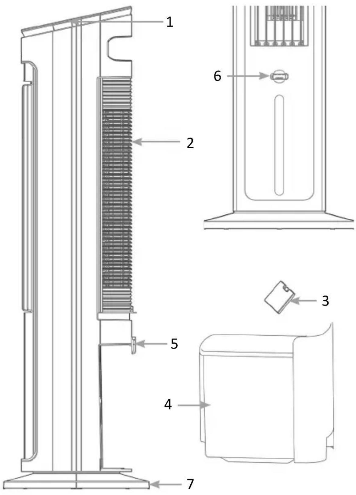
| Number Description | |
| 1 | Operating elements |
| 2 Air inlet | |
| 3 Ice pack | |
| 4 Water tank | |
| 5 Water tank lock | |
| 6 Aroma compartment | |
| 7 Stand | |
Operating elements
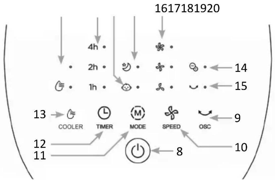
flowchart
graph TD
    A["1617181920"] --> B["4h"]
    B --> C["2h"]
    C --> D["1h"]
    D --> E["COOLER"]
    E --> F["TIMER"]
    F --> G["MODE"]
    G --> H["SPEED"]
    H --> I["OSC"]
    I --> J["10"]
    J --> K["8"]
    K --> L["12"]
    L --> M["11"]
    M --> N["13"]
    N --> O["14"]
    O --> P["15"]
| Number Description | |
| 8 | “ON/OFF” button |
| 9 “OSC. button | |
| 10 “SPEED” | button |
| 11 “MODE” | button |
| 12 “TIMER” | button |
| 13 “COOLER” | button (air cooling on/off) |
| 14 Operating control lamp | |
| 15 Oscillation indicator light | |
| 16 Speed control lights | |
| 17 Night mode indicator light | |
| 18 Child mode indicator light | |
| 19 Timer control lights | |
| 20 Air cooling indicator light | |
Remote control
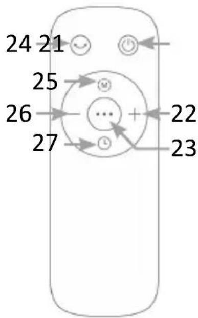
| Number Description | |
| 21 | “ON/OFF” button |
| 22 “+” button | |
| 23 “Air cooling ON/OFF” button | |
| 24 “OSC.” button | |
| 25 “MODE” button | |
| 26 “-” button | |
| 27 “TIMER” button | |
4. key functions
| Key Description | |
| “OSC” button | Switches the oscillation on and off |
| “ON/OFF” button Switches the unit on and off | |
| “TIMER” button Activates the timer function (1-7 hrs) | |
| “MODE” button Switches the mode between “Natural” and “Night | |
| “Air cooling ON/OFF” button | Activates air cooling (While the appliance is in cooling mode, do not remove the water tank. |
| “SPEED” button (“+” / “-”) | Anpassen zwischen den 3 vorhandenen Geschwidigkeitsstufen |
5. assembly
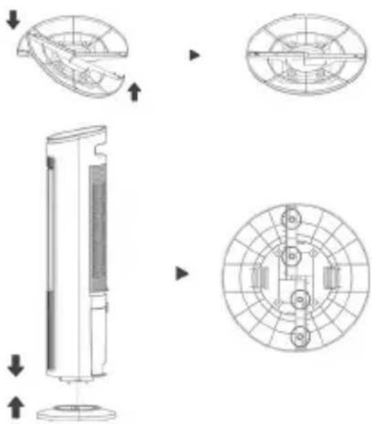
-
Take the two parts of the stand out of the box, hold them against each other and turn them in opposite directions until the two outer lugs click into place.
-
Press the air cooler into the stand in the correct orientation until it locks into the unit. You can then secure the stand to the unit with screws.
5.1 Start-up
Take the unit out of the packaging and check the unit and the scope of delivery shown above. Please contact the seller if any part is missing or damaged. Insert 2x AAA batteries into the remote control. Make sure the polarity of the contacts is correct.
Connect the mains cable to a properly connected socket and ensure that the mains voltage is correct, as indicated on the rating plate.
6. Use
Place the unit in a suitable location and connect the unit to a properly installed power outlet.
Insert 2x AAA batteries into the remote control. Make sure that the polarity of the contacts is correct.
Attention! The cooling effect of the air cooling only exists in the direct air flow of the unit.
6.1 Adjusting speed levels
You have the option of choosing between three different speed levels. Press the "SPEED" button ("+" / "-" on the remote control) on the remote control or on the control panel of the air cooler to set the speed of the fan.
6.2 Mode selection
You can choose between child and night mode. The mode can be changed via the “MODE” key. If you want to use the normal mode, press the key so often that neither of the two mode indicator lights is illuminated.
Night mode
| Night mode | Step 1 Step 2 Step 3 | |||||
| Level Duration Level Duration Level Duration | ||||||
| 1 2 30min | in 1 30min | 1 Switched on | ||||
| 2 3 30min | in 2 30min | 1 Switched on | ||||
Children's mode
The fan speed changes automatically every 5 seconds between the available speeds in 1 minute cycles. The fan speed is controlled automatically and cannot be adjusted.
6.3 Timer function
The air cooler offers different timer levels that can be adjusted hourly up to a maximum time of 7 hours.
Switch-on timer
- Make sure the unit is connected to the mains and is in standby.
- Press the timer button to select the desired time (one to seven hours).
- The timer indicator lights up permanently.
- After the set time has elapsed, the appliance switches on.
Switch-off timer
To do this, press the „Timer“ button on the remote control or on the control panel of the fan. Press it repeatedly to increase the duration of the timer.
Switch off timer function
To switch off the timer function, press the „ON/OFF“ key twice or press the timer key repeatedly until none of the timer control lights are illuminated.
6.4 Cooling mode
Make sure that there is water in the water tank and never remove the water tank during operation.
Fill the cold packs with water and place them in a freezer compartment. When the cold packs (3) are sufficiently cold, place them in the water tank to increase the cooling effect.
The unit runs as a simple fan in normal mode. If you want to switch on the air cooling additionally, press the “Air cooling ON/OFF key on the remote control or on the control panel.
As soon as the air cooling is switched on, the control light on the control panel lights up.
Attention! For maximum effect, we recommend staying within the range of the air flow.
6.5 Aroma function
Notes:
- Use only essential oils.
- Read and follow the safety and usage instructions for essential oils carefully before use.
- Switch off the appliance and make sure that the appliance is completely disconnected from the power supply before adding the oil to the aroma compartment.
- If you have allergies to certain essential oil ingredients, do not use them. Do not use the aroma function in the presence of babies, pregnant women or women who are breastfeeding.
- Consult a doctor or follow medical advice before using essential oils for respiratory problems.
-
If you feel uncomfortable or irritated while using the essential oil, stop the appliance and do not use this function again.
-
Switch off the appliance completely and disconnect it from the power circuit.
- Pull out the aroma compartment (6) from the front of the appliance.
- Add approx. 2-3 drops (max. 3) of essential oils to the aroma pad.
- Then put the aroma compartment back into the appliance.
7. fill water tank
- Switch off the machine and disconnect it from the mains.
- Turn the water tank lock 90° clockwise and carefully pull out the water tank.
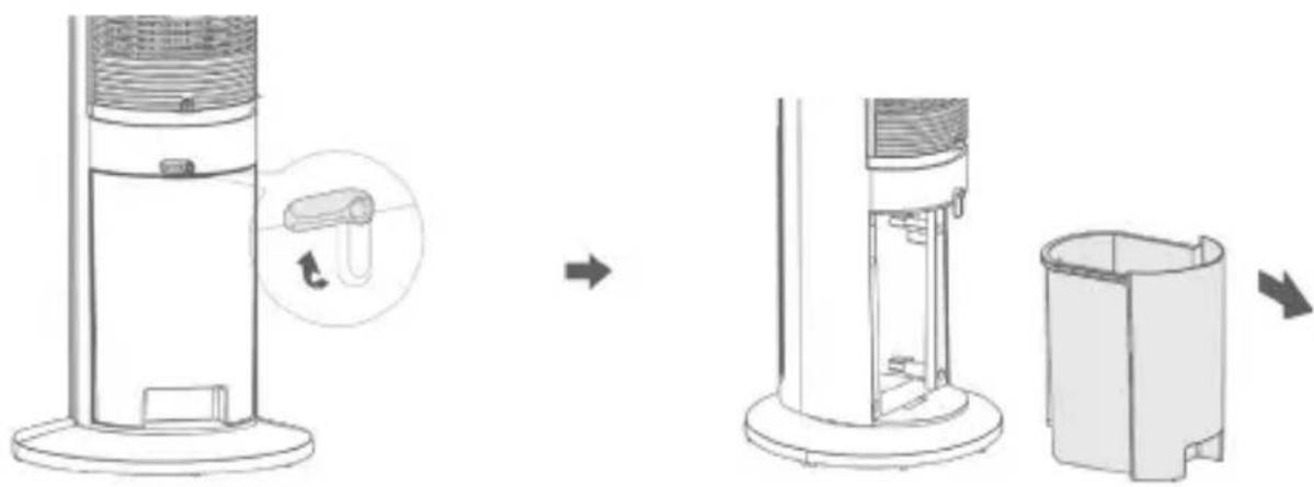
natural_image
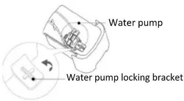
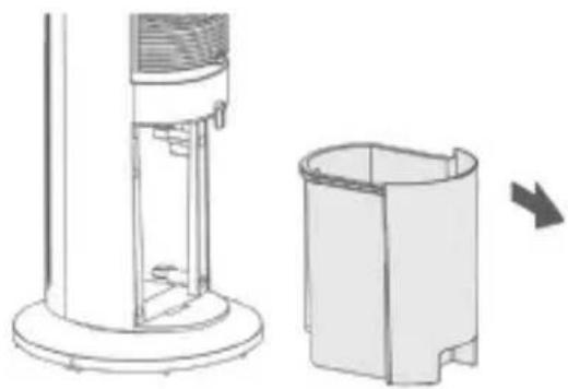
Diagram showing a device interior with a top-mounted tower, a close-up of its internal component, and a final view of a cylindrical container (no text or symbols present)- Turn the water pump locking bracket 90^ clockwise and remove the water pump from its holder. Then remove the water tank completely.
natural_image
Technical line drawing of a cylindrical device with a side view showing internal components and an arrow indicating rotation (no text or symbols)- Then push the water tank back in and turn the water tank lock 90^ anticlockwise to hold the water tank firmly in position.
Note: If the water level is too low, three beeps will sound and the fan cooling indicator light will continue to flash until the air cooling is deactivated or the water tank is refilled.
Make sure that you always empty the unit completely when not in use.
8 Cleaning and care
Attention! Please disconnect the mains plug from the socket before you start cleaning!
Use a cloth slightly moistened with water for cleaning. Under no circumstances should the unit be immersed in water for cleaning. This could result in an electric shock or fire!
8.1 Cleaning the filter
-
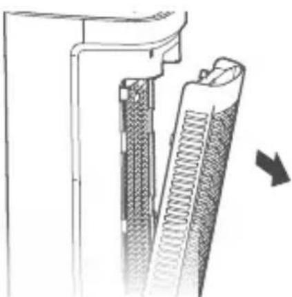
Clean the air filter of the unit approx. every fortnight. The air filter is located at the air outlet (2) / the filter flap.
-
First unscrew the filter housing protection screw and pull the filter housing downwards. The filter housing can now be removed from the unit by pulling it slightly from above.
natural_image
Technical diagram of a mechanical component with internal structure and directional arrow (no text or symbols)Note: The appliance must be switched off and the mains plug disconnected from the socket before cleaning the filter!
- Remove the filter and take the filter out of the filter housing.
- Use a brush or hoover to remove dust or particles from the dry filter.
- Then put the filter back into the filter housing and mount it again on the back of the unit.
8.2 Cleaning the water tank
- The water tank must be cleaned after 2 weeks at the latest to prevent the possible occurrence of mould or bacteria.
- Remove and clean the water pump as described above. It is recommended to clean the pump regularly every 3 months to prolong its life.
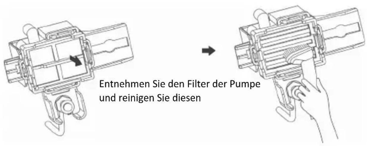
- Remove the water tank and clean it with a mild detergent and warm water.
- Then dry the water tank with a soft cloth.
- First insert the pump into the water tank and then insert the water tank into the machine.
Attention! Never use boiling water to clean the tank.
8.3 Storage
If you do not intend to use the machine for a longer period of time and want to store it, you must empty the water tank completely.
Run the unit for four hours in fan-only mode at low speed to allow the inside of the unit to dry completely.
Then store the unit in a dry place.
9. safety instructions and disclaimer
Never attempt to open the unit to carry out repairs or modifications. Avoid contact with the mains voltages. Do not short-circuit the product. The unit is not water-proof, please use it only in dry conditions. Protect it from high humidity, water and snow. Keep the unit away from high temperatures.
Do not expose the unit to sudden temperature changes or strong vibrations as this may damage the electronic parts. Check the unit for damage before use. The unit should not be used if it has been bumped or damaged in any way. Please observe the national regulations and restrictions. Do not use the appliance for purposes other than those described in the instructions. This product is not a toy.
Keep it out of the reach of children or mentally impaired persons. Any repair or modification to the unit not carried out by the original supplier will invalidate the warranty or guarantee. The appliance may only be used by persons who have read and understood these instructions. The specifications of the appliance are subject to change without prior notice.
10. disposal instructions
According to the European WEEE Directive, electrical and electronic equipment must not be disposed of with household waste. Their components must be recycled or disposed of separately because toxic and hazardous components can cause lasting damage to the environment if disposed of improperly. As a consumer, you are obliged under the Electrical and Electronic Equipment Act (ElektroG) to return electrical and electronic equipment free of charge at the end of its service life to the manufacturer, the point of sale or to public collection points set up for this purpose. Details are regulated by the respective national law. The symbol on the product, the operating instructions and/or the packaging indicates these regulations. By separating, recycling and disposing of old appliances in this way, you are making an important contribution to protecting our environment.
11. notes on battery disposal
In connection with the sale of batteries or the delivery of devices containing batteries, the supplier is obliged to inform the customer of the following: The customer is legally obliged to return used batteries as an end user. He can return used batteries, which the supplier stocks or has stocked as new batteries, free of charge to the supplier's dispatch warehouse (dispatch address). The symbols shown on the batteries have the following meaning: Pb = battery contains more than 0.004 mass percent lead, Cd = battery contains more than 0.002 mass percent cadmium, Hg = battery contains more than 0.0005 mass percent mercury.

The symbol of the crossed-out dustbin means that the battery must not be disposed of in household waste.
WEEE Directive: 2012/19/EU WEEE Register No: DE 67896761
WD Plus GmbH hereby declares that the device 306537 / 306538 is in compliance with the essential requirements and the other relevant provisions. A complete declaration of conformity can be obtained from: WD Plus GmbH, Wohlenbergstraße 16, 30179 Hannover, https://model.ganzeinfach.de/306537.
natural_image
Technical line drawings of a cylindrical device with internal components and directional arrows indicating assembly or transformation (no text or symbols present)natural_image
Diagram showing a device interior with a top-mounted tower, a close-up of its internal component, and a final view of a cylindrical container (no text or symbols present)natural_image
Technical line drawing of a mechanical assembly inside a housing, showing internal components and two circular insets (no text or labels)natural_image
Diagram of a vertical cylindrical device with a magnified inset showing a mechanical component (no text or symbols present)natural_image
Technical diagram of a mechanical component with internal structure and directional arrow (no text or symbols)natural_image
Technical line drawings of a cylindrical device with internal components and external views (no text or symbols)natural_image
Diagram showing a device interior with a top-mounted tower, a side-view view of a device with a scroll, and a final container (no text or symbols present)natural_image
Technical line drawing of a cylindrical device with internal components and an external housing, showing a rightward arrow indicating rotation (no text or symbols present)natural_image
Technical diagram of a mechanical component with internal structure and directional arrow (no text or symbols)natural_image
Technical line drawings of a device with internal components and directional arrows indicating assembly or transformation (no text or symbols)natural_image
Diagram showing a device's internal structure before and after assembly, with no visible text or symbols.natural_image
Technical diagram of a mechanical component with internal structure and directional arrow (no text or symbols)MO-FR 9:30am - 18pm CET

brandson-equipment.de
- Important safety instructions for this ap- pliance
- scope of delivery
- technical data
- Remote control
- key functions
- assembly
- Start-up
- Use
- Adjusting speed levels
- Mode selection
- Children's mode
- Timer function
- Switch-on timer
- Switch-off timer
- Switch off timer function
- Cooling mode
- Aroma function
- Notes:
- fill water tank
- Cleaning and care
- Cleaning the filter
- Cleaning the water tank
- Storage
- safety instructions and disclaimer
- disposal instructions
- notes on battery disposal
Brand : Brandson
Model : 306538
Category : Air Conditioning