KJ-45 - Sharpener Tormek - Free user manual and instructions
Find the device manual for free KJ-45 Tormek in PDF.


User questions about KJ-45 Tormek
0 question about this device. Answer the ones you know or ask your own.
Ask a new question about this device
Download the instructions for your Sharpener in PDF format for free! Find your manual KJ-45 - Tormek and take your electronic device back in hand. On this page are published all the documents necessary for the use of your device. KJ-45 by Tormek.
USER MANUAL KJ-45 Tormek
KJ-45/KJ-140 Instruction
natural_image
Illustration of two thermos IV push-button lever holders with labeled parts (no text or symbols beyond branding)KJ-45 Centering Knife Jig
natural_image
Close-up of hands using a tool to adjust or install a mechanical component (no visible text or symbols)MOST KNIVES
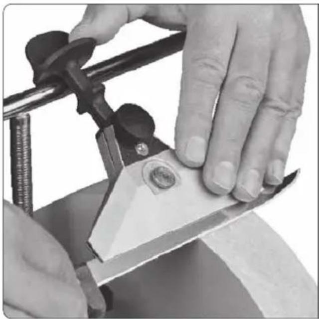
For most knives, longer knives with rigid blades, straight draw knives and woodsplitting knives.
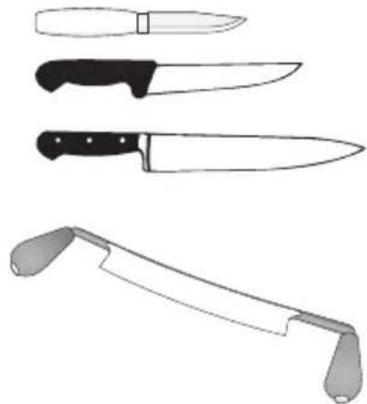
natural_image
Illustration of a knife with three different blade designs, no text or symbols presentPositioning of Machine

natural_image
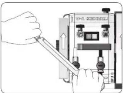
Illustration of two hands holding a device with internal components, showing open and closed states (no text or symbols)Sharpening direction: Edge leading or edge trailing.
Design
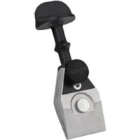
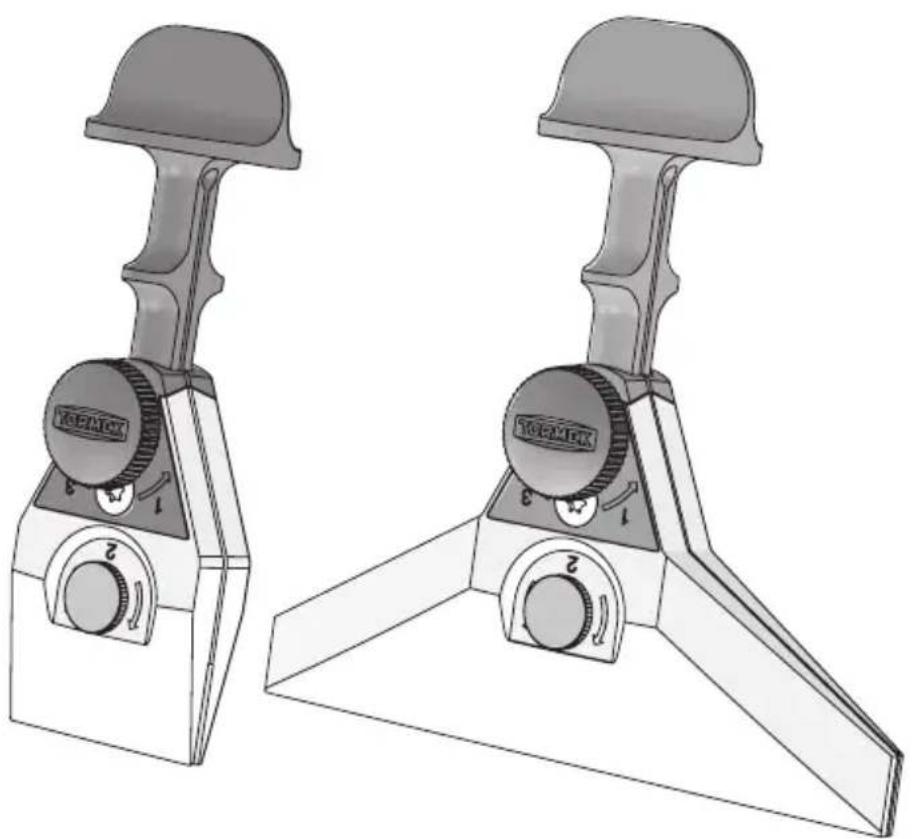
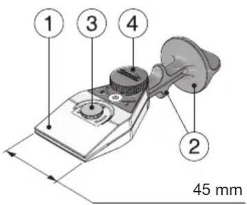
The KJ-45 Centering Knife Jig comprises an adjustable clamp (1) for holding knives of varying thickness and blade geometry centered in the jig, and a handle with two fixed stops (2) for sharpening blades of different heights. The jig is adjusted to the knife thickness with the screw (3). The knife is screwed into the clamp using the knob (4) and locked centered in the jig.
The jig rests with one of the two stops on the Universal Support, which is adjusted to the approximate height. The exact edge angle is set with the Micro Adjust on the Universal Support. Make sure to use the same stop throughout the setting and sharpening process.
text_image
1 3 4 2 45 mmMounting the knife in the jig
natural_image
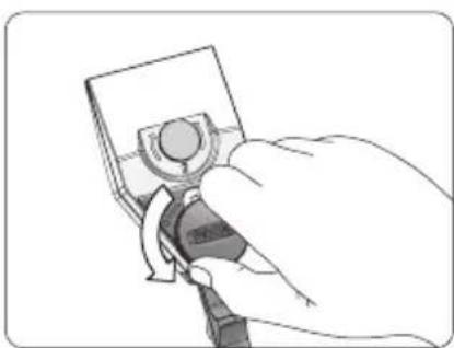
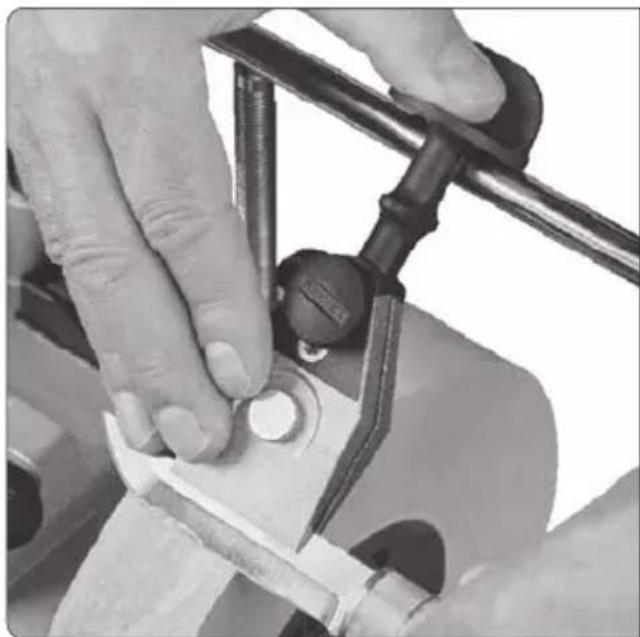
Hand holding a small electronic device with a circular button, no visible text or symbols- Unscrew the tightening knob (counterclockwise), and the small adjusting screw if needed, so that the blade of the knife fits in the clamp.
text_image
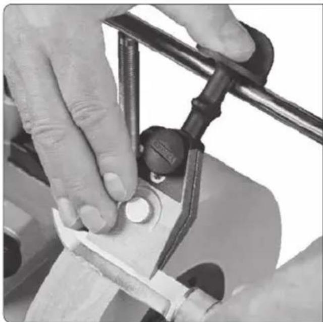
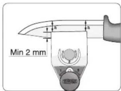
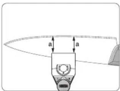
Min 2 mm a a 1 2 3- Put your knife blade in the jaws of the clamp, as far in as possible (minimum 2 mm). The clamp is usually attached on the center of the blade. Attach the knife in the jig so that the distance from the clamp to the knife's edge is the same at both of the outer edges of the clamp (distance a).
text_image
a a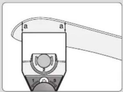
text_image
a a 2 1 3Tip For knives with an extreme bend towards the tip of the blade (e.g. skinning knives), you can benefit from attaching the jig at the tip of the blade, with the same principles as above. This makes it easier to trace the shapes of the blade and achieve an even bevel.
natural_image
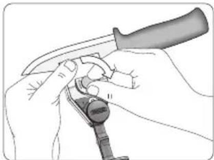
Illustration of hands using a tool to adjust or install a mechanical component (no text or symbols visible)- Adjust the jig with the small adjusting screw to fit the thickness of the knife.
natural_image
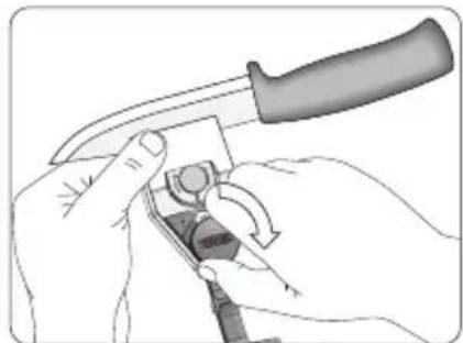
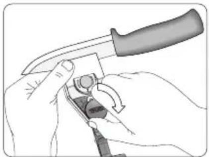
Illustration of hands using a knife to adjust or install a component (no text or symbols visible)- Tighten the knob. 5. Make sure the blade is firmly mounted and enclosed before you start sharpening.
natural_image
Technical line drawing of a medical or surgical tool with a pointed tip and attached clip (no text or symbols)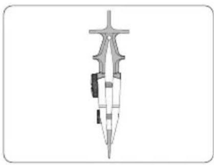
natural_image
Cross-sectional diagram of a mechanical component or tool (no text or symbols visible)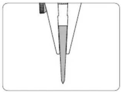
natural_image
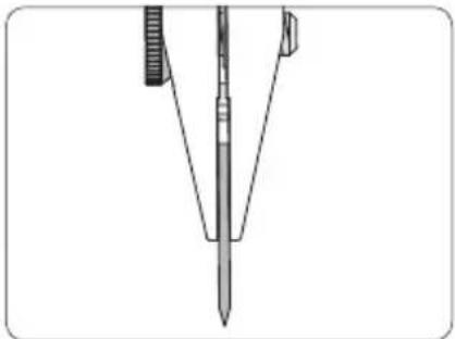
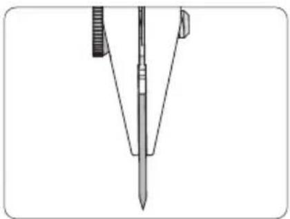
Diagram of a pipette tip with a pointed tip and a handle, showing internal structure (no text or labels)Important Make sure the clamp grips the blade so that both jaws of the clamp enclose and are in full contact all the way along the blade so as to ensure that the knife is firmly centered in the jig. Even wedge-shaped blades must be in contact with the clamp along their entire length. You may need to go back and loosen the small adjusting screw slightly before tightening the knob so that the clamp can grip wedge-shaped blades properly.
Minimum blade height
text_image
Min 12 mm Min 2 mm 1 2 3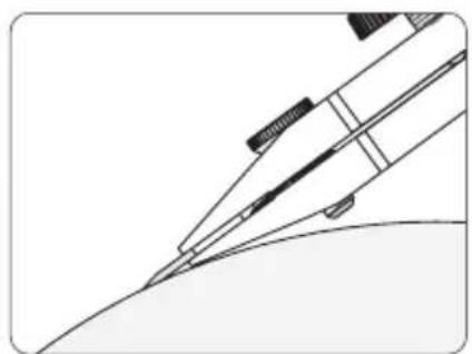
natural_image
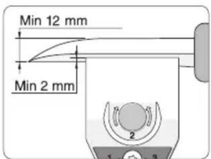
Line drawing of a pen writing on paper (no text or symbols present)The jig needs to grip the blade by at least 2 mm. You can sharpen knives with a minimum blade height of 12 mm at the attachment point, with a total edge angle of 20^ . To sharpen smaller knives, use the SVM-00 Small Knife Holder together with the KJ-45 Centering Knife Jig.
Blade thickness
text_image
Max 10 mm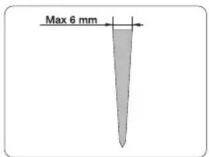
text_image
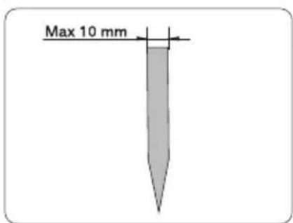
Max 6 mmYou can use the KJ-45 Centering Knife Jig with your thinnest knives, up to knives with a blade 10 mm thick. The maximum thickness for knives with a tapered cross-section, tapering from the back to the bevel, is about 6 mm at the back.
Replicating the existing edge angle
natural_image
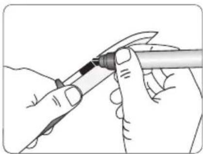
Illustration of hands using a tool to apply a pen tip (no text or symbols visible)- Color the bevel with the EM-15 Edge Marker so that you can see where sharpening will occur.
natural_image
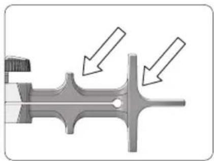
Mechanical caliper component diagram showing two directional arrows indicating movement or force (no text or symbols present)- Choose which of the two stops you want to use. For taller knives, use the bottom stop.
natural_image
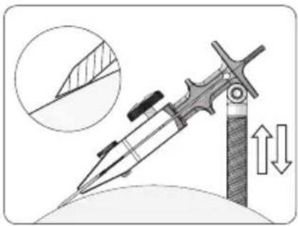
Illustration of a folding knife with directional arrows indicating movement or force (no text or symbols)- Adjust and lock the Universal Support so that the heel of the bevel touches the grinding wheel.
natural_image
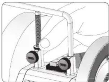
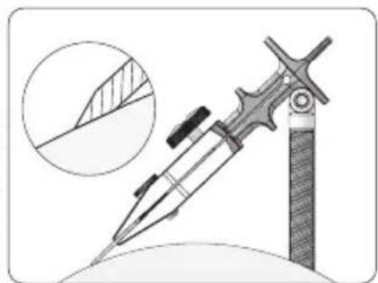
Mechanical assembly diagram showing a hand operating a vehicle wheel with attached components (no text or symbols visible)- Raise the Universal Support with the Micro Adjust until the whole bevel touches the grinding wheel. Check by moving the grinding wheel by hand to see where sharpening will take place. You have reached the correct sharpening angle when the ink from the marker is worn off from the entire bevel.
natural_image
Illustration of a pen writing on paper with an inset showing a cross-section (no text or symbols)Setting a new edge angle and measuring an edge angle
text_image
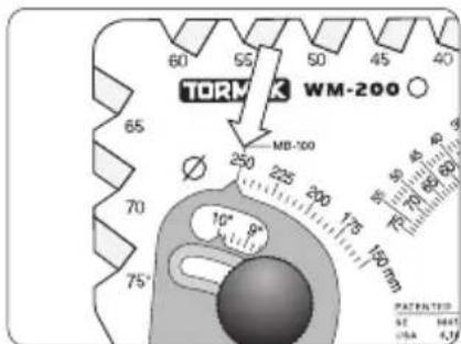
TORMK WM-200 60 55 50 45 40 65 MB-100 Ø 250 225 200 175 150 mm 70 75° 10° 8° PATENTED 62 6643 1564 4.19- Set the diameter of the grinding wheel on your WM-200 AngleMaster.
text_image
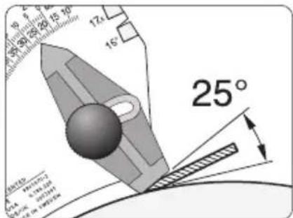
19° 20° 21° 22° 23° 24° 25° 17° 16° 25° SPTA 100mm 100mm 100mm 100mm 100mm 100mm 100mm 100mm 100mm 100mm 100mm 100mm 100mm 100mm 100mm 100mm 100mm 100mm 100mm 100mm 100m- Set the desired edge angle on the AngleMaster. Adjust the Universal Support so that the bevel is in contact with the angle setter.
text_image
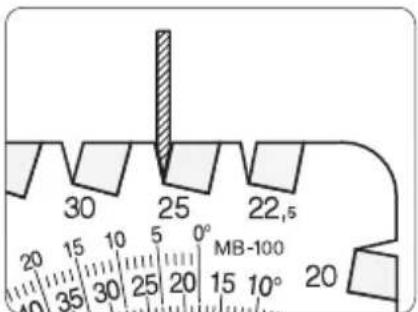
30 25 22,5 20 15 10 5 0° MB-100 40 35 30 25 20 15 10° 20- You can measure the edge angle in the grooves of the AngleMaster, provided that the bevels are wide enough.
Thin Knives
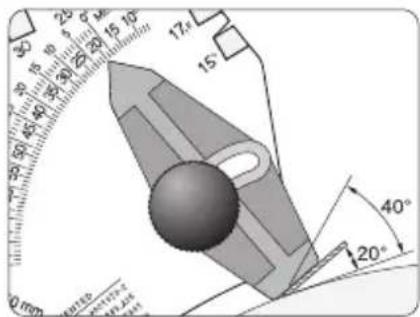
When setting an edge angle on thin knives, the bevel is short and can therefore be difficult to align with the angle setter on your WM-200 AngleMaster. In that case, you can allow the entire blade to remain in contact with the angle setter instead of just the bevel. The angle setter must then be set to half the desired edge angle.
text_image
30 25 φ 15° 17 15° 90 80 60 40 20 10 0 mm 40° 20°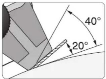
text_image
40° 20°It is important for the knife to be sharpened with the correct edge angle. With a narrow edge angle ( 20^ ), the knife cuts easily but the edge can be easily damaged and is not as durable. A larger edge angle ( 40^ ) gives a stronger, more durable edge, but the knife does not cut as easily. The optimal edge angle also depends on the quality of the steel.
text_image
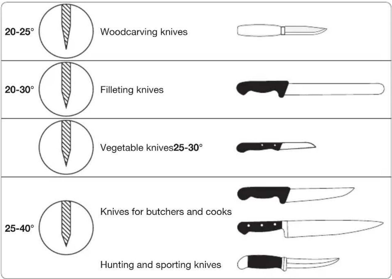
20-25° Woodcarving knives 20-30° Filleting knives Vegetable knives25-30° 25-40° Knives for butchers and cooks Hunting and sporting knivesSharpening
natural_image
Illustration of hands operating a camera module with a tool, no text or symbols present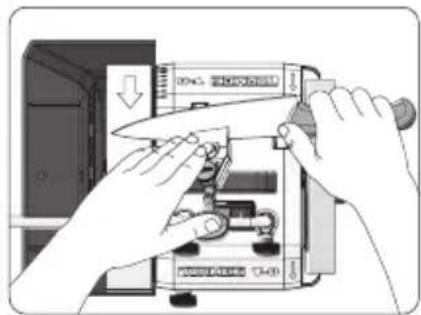
natural_image
Illustration of hands installing or adjusting a device component with a tool (no text or symbols visible)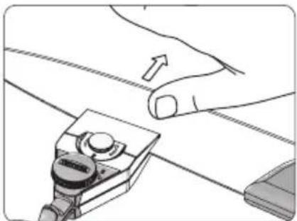
natural_image
Illustration of a hand using a tool to adjust or install a piece of paper (no text or symbols visible)-
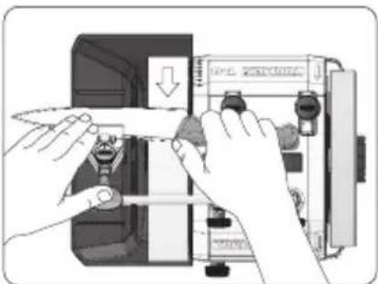
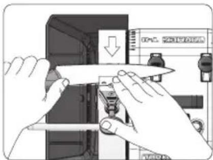
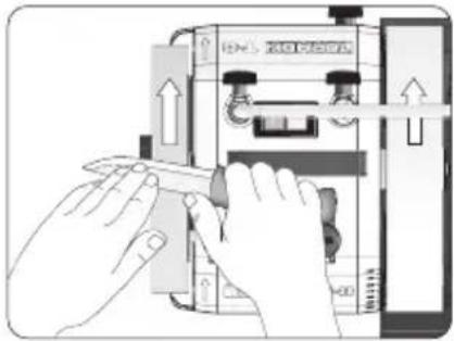
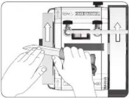
Hold the knife and the jig as illustrated. Make sure that you press your thumb or palm against the jig so that the stop is always in contact with the Universal Support. Move the knife back and forth across the grinding wheel at a steady pace. Ensure that the blade is in contact with the entire width of the grinding wheel. When you reach the curved part of the blade, lift the knife handle forward and upwards so that it has the same bevel as the rest of the blade. Do not pull the handle towards you, this will give a taller bevel on the tip than on the rest of the blade.
-
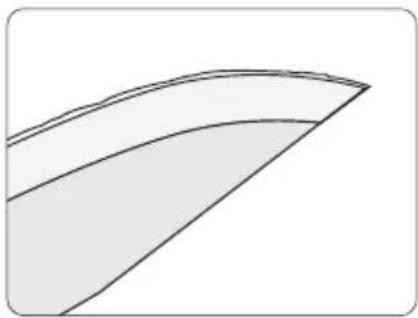
Grind until a burr forms along the entire top of the blade. This can be felt by using a finger to lightly stroke the blade from the back of the knife and down over the edge.
Tip Hold the knife so that the water flows evenly over the blade. The blade is then in contact with the entire width of the grinding wheel, which is important for an even bevel.
natural_image
Abstract geometric shape with curved lines and a shaded triangular region (no text or symbols)In good light, the burr will show up as a pale line. When you have a burr along the entire blade, the first side is finished.
natural_image
Illustration of hands installing or adjusting a component with a downward arrow (no text or symbols visible)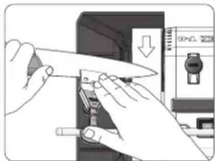
natural_image
Illustration of hands using a knife to adjust or install a device (no text or symbols visible)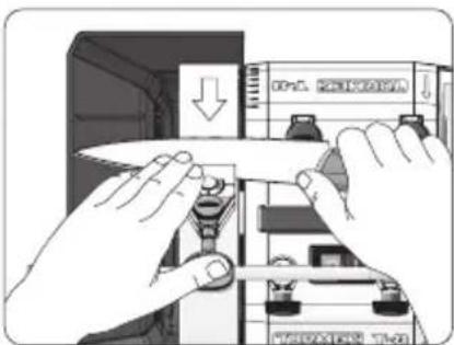
text_image
Diagram showing hands installing or adjusting a document with directional arrows and labeled components-
When the first side is sharpened, turn the jig upside-down while the knife is still fixed in the jig and sharpen the other side. Now the burr appears immediately as it has already appeared on the underside and bends up. Sharpen as much as on the first side to obtain a symmetrical edge.
-
The burr will be weakened and more easily removed if you grind the first side again with very light pressure.
Tip Sharpening long knives can be facilitated if you remove the honing wheel.
Edge trailing (away from the edge)
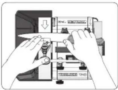
The instruction has shown you how to sharpen knives towards the edge with the Universal Support placed vertically. This way works for all knife lengths. You can also place the Universal Support in the horizontal position and grind with the edge. For sharpening with the edge, there are limitations to which knives you can sharpen as the lower stop or the knob on the clamp may touch the leg of the Universal Support. These limitations are due to several factors.
Factors affecting the option to sharpen with the edge trailing:
• Which Tormek model you have
• How long the knife is
• How tall the blade is
• Where on the blade the jig is attached
• How deeply on the knife blade the jig is attached
• The sharpening angle.
We recommend that you try out what works on the knife you are sharpening at the time, with its conditions.
text_image
Diagram showing hands operating a mechanical device with labeled components and directional arrows indicating process flow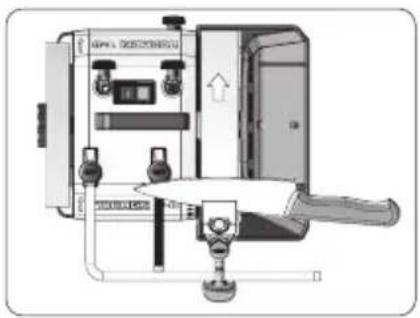
natural_image
Technical diagram of an electrical enclosure with control panel and door (no visible text or labels)Honing
natural_image
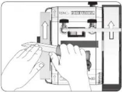
Illustration of hands operating a mechanical device with arrows indicating motion (no text or symbols)Turn the machine so that the honing wheel rotates away from you. Remove the knife from the jig. Hone and polish the bevels on the honing wheel. Make sure that the entire bevel is in contact with the honing wheel. Move the knife back and forth a few times on each side of the blade until the burr disappears.
natural_image
Illustration of hands operating a mechanical device with directional arrows indicating movement (no text or symbols)You can ensure that the burr is completely removed by drawing the edge gently over a fingernail. This will allow you to easily feel any unevenness. You can also cut a piece of paper. If the knife gets stuck or the cut is uneven, there is still a burr and you need to hone a little more.
If the burr is not completely gone, you need to spend more time on honing. When you have no burr left at all, your knife will be razor sharp with a durable edge
Important Always hone with the edge trailing. Place the machine as shown so that the honing wheel rotates away from you.
You can also keep the knife mounted in the jig and hone on the leather honing wheel at a controlled angle. The same factors apply here for any restrictions on which knives you can hone as for sharpening with the edge trailing.
When honing using the jig on the universal support, in most cases you will need to remove the grinding wheel to avoid striking it with the knife. When you remove the grinding wheel from the machine, remember to replace it with the white transport sleeve on the main shaft so as to keep the main shaft in place.
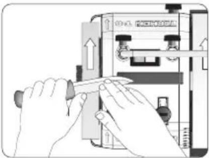
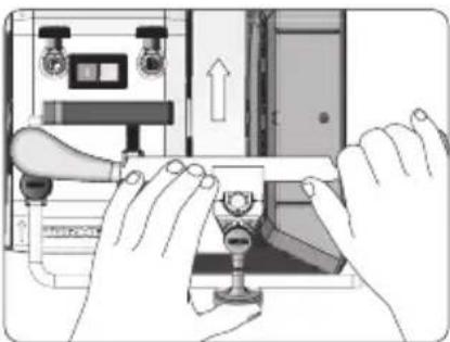
Straight drawknives and wood splitting knives
natural_image
Illustration of hands operating a device with a glass and control panel (no text or symbols visible)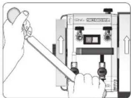
natural_image
Illustration of a hand holding a tool next to an electrical control panel (no text or symbols visible)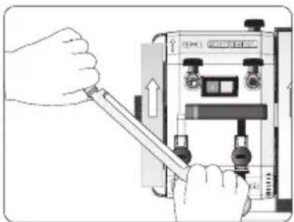
natural_image
Illustration of hands using a tool to adjust or install an electronic device (no text or symbols visible)-
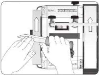
Press the jig down so that the stop is always in contact with the Universal Support. Ensure that sharpening takes place across the entire width of the grinding wheel.
-
Hone free-hand. Hold the knife diagonally to clear the grinding wheel. Hone both sides alternately
KJ-140 Wide Centering Knife Jig
natural_image
Close-up of hands using a tool to cut or apply a small object, no visible text or symbolsLONG, FLEXIBLE KNIVES
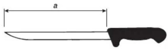
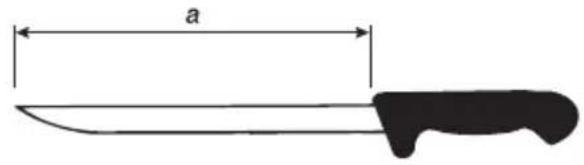
E.g. filleting knives. Minimum blade length (a) 160 mm.
text_image
aPositioning of Machine
natural_image
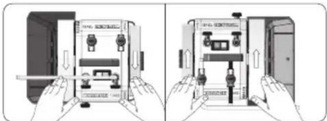
Illustration of two hands installing or adjusting a device inside an electrical enclosure (no text or symbols visible)Sharpening direction: Edge leading or edge trailing.
Design
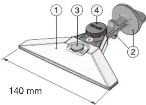
The KJ-140 Wide Centering Knife Jig comprises an adjustable clamp (1) for holding knives of varying thickness and blade geometry, and two fixed stops (2) for sharpening blades of different heights. The jig is adjusted to the knife thickness with the screw (3). The knife is screwed into the clamp with the knob (4) and locked centered in the jig.
text_image
140 mmThe KJ-140 Wide Centering Knife Jig is designed to stabilize knives with flexible blades longer than 160 mm, for even and controlled sharpening. It works in the same way as the KJ-45 Centering Knife Jig, but with a wider clamp that gives more support to flexible knife blades. Follow the instructions on pages 4-10 for installation and use instructions. Please note that the KJ-140 Wide Centering Knife Jig does not work with the SVM-00 Small Knife Holder.
KJ-45 Centrerande knivjigg
natural_image
Close-up of hands using a tool to adjust or install a mechanical component (no visible text or symbols)DE FLESTA KNIVAR
natural_image
Illustration of a knife with three different blade designs, no text or symbols presentnatural_image
Illustration of hands installing or adjusting a device panel, showing internal components and directional arrows (no text or symbols)natural_image
Hand holding a small mechanical component with a circular knob, no visible text or symbolstext_image
a a 2 1 3natural_image
Illustration of hands using a tool to adjust or install a mechanical component (no text or symbols visible)- Anpassa jiggen till kniv- bladets tjocklek med den lilla justerskruven.
natural_image
Illustration of hands using a knife to adjust or install a piece of paper (no text or symbols visible)- Dra åt ratten.
natural_image
Diagram of a medical or surgical tool with a pointed tip and two vertical bars, no text or symbols present.natural_image
Cross-sectional diagram of a mechanical component or tool (no text or symbols visible)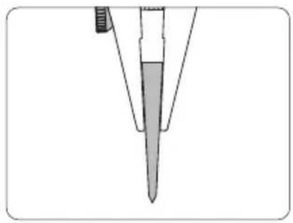
natural_image
Diagram of a pipette tip with a pointed tip and a handle, showing no text or symbolsnatural_image
Line drawing of a pen writing on a curved surface (no text or symbols)natural_image
Illustration of hands using a tool to apply a pen tip (no text or symbols visible)natural_image
Mechanical caliper component diagram showing two directional arrows indicating movement or force (no text or symbols present)natural_image
Illustration of a mechanical tool with an arrow indicating motion, showing a cross-section and directional arrows (no text or symbols)natural_image
Technical diagram of an aircraft landing gear assembly (no text or symbols visible)natural_image
Illustration of a pen writing on paper with an inset showing a cross-section (no text or symbols)natural_image
Illustration of hands operating a device with a scroll wheel and directional arrow (no text or symbols)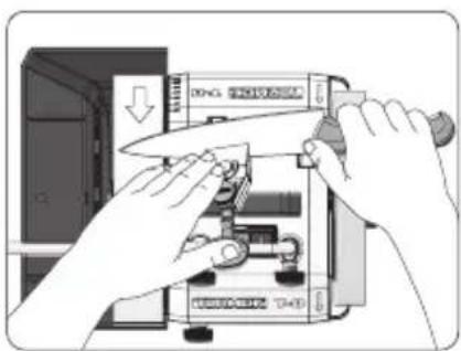
natural_image
Illustration of hands operating a device with a knife, no visible text or symbols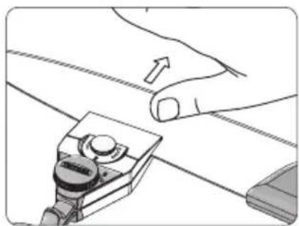
natural_image
Illustration of a hand using a tool to adjust or install a component, with no visible text or symbols.natural_image
Simple line drawing of a curved, layered shape with no text or symbolsnatural_image
Illustration of hands installing or adjusting a panel on a device (no text or symbols visible)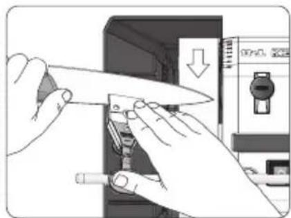
natural_image
Illustration of hands using a knife to adjust or install electronic components (no text or symbols visible)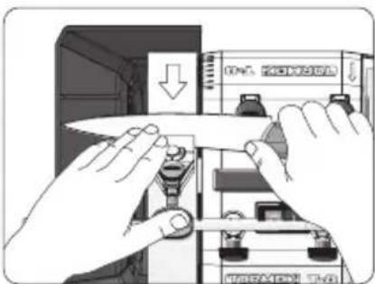
natural_image
Illustration of hands installing or adjusting a document inside a device (no text or symbols visible)text_image
Diagram showing hands operating a battery with a labeled switch and directional arrow indicating process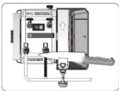
natural_image
Technical diagram of an electrical control box with switches and a lever mechanism (no text or labels visible)Bryning
natural_image
Illustration of hands operating a mechanical device with arrows indicating motion (no text or symbols)text_image
Diagram showing hands operating a mechanical device with directional arrows and labels like 'CNCL' and 'PHOCHOLICATOR'natural_image
Illustration of hands operating a device with a handle and control panel (no text or symbols visible)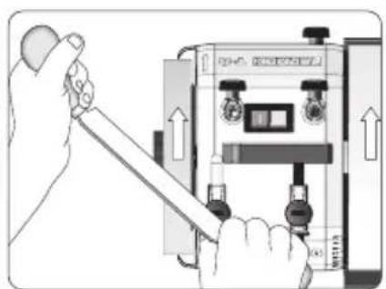
natural_image
Illustration of a hand using a tool to adjust or install a device (no text or symbols visible)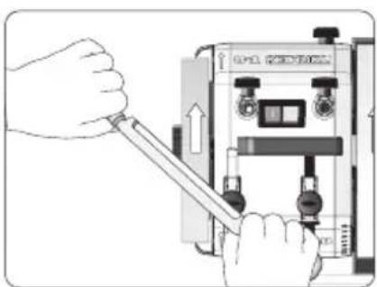
natural_image
Illustration of hands using a tool to adjust or install a device (no text or symbols visible)natural_image
Close-up of hands using a metal cutting tool to work on a flat surface (no text or symbols visible)LÅNGA BÖJLIGA KNIVAR T.ex. filéknivar. Minsta bladlängd (a) 160 mm.
text_image
anatural_image
Illustration of hands installing or adjusting a device panel inside an enclosure (no text or symbols visible)natural_image
Close-up of hands using a tool to adjust or install a mechanical component (no visible text or symbols)DIE MEISTEN MESSER
natural_image
Illustration of three different kitchen utensils: a knife, a knife with handle, and a knife blade (no text or symbols)natural_image
Illustration of two hands installing or adjusting a device panel with buttons and switches (no text or symbols visible)natural_image
Hand holding a small electronic device with a circular button, no visible text or symbolstext_image
a a 2 1 3natural_image
Illustration of hands using a knife to adjust or install a mechanical component (no text or symbols visible)natural_image
Illustration of hands using a tool to adjust or install a piece of material (no text or symbols visible)natural_image
Line drawing of a medical or surgical tool with a pointed tip and attached clip (no text or symbols)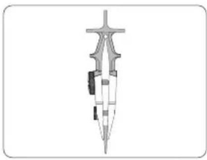
natural_image
Cross-sectional diagram of a mechanical or architectural component (no text or symbols visible)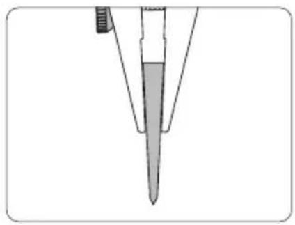
natural_image
Diagram of a pipette tip with a pointed tip and a handle, showing internal structure (no text or labels)natural_image
Pure line drawing of a pen tip and ruler on a curved surface (no text or symbols)natural_image
Illustration of hands using a tool to apply a pen tip (no text or symbols visible)natural_image
Mechanical caliper component diagram showing internal structure with two arrows indicating direction (no text or symbols)natural_image
Illustration of a sword with an arrow indicating upward and downward motion, showing a cross-section view (no text or symbols)natural_image
Technical diagram of an aircraft wing with landing gear and control components (no text or symbols)natural_image
Illustration of a pen writing on paper with an inset showing a cross-section (no text or symbols)natural_image
Illustration of hands operating a mechanical device with a downward arrow indicating action (no text or symbols present)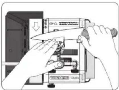
natural_image
Illustration of hands using a knife to adjust or install electronic components on a device (no text or symbols visible)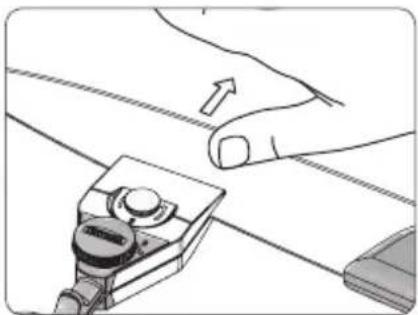
natural_image
Illustration of hands using a tool to adjust or install a component, with an arrow indicating the process (no text or symbols present)natural_image
Abstract geometric shape with curved and straight lines forming a triangular form (no text or symbols)text_image
Diagram showing hands installing or adjusting a component with a downward arrow, likely illustrating a mechanical or electrical assembly process.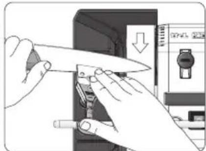
natural_image
Illustration of hands using a knife to adjust or install a device (no text or symbols visible)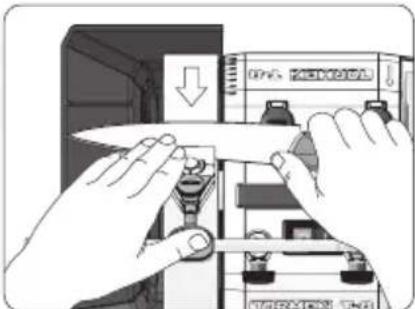
text_image
Diagram showing hands installing or adjusting a document with a downward arrow, likely illustrating a process or installation procedure.text_image
Diagram showing hands operating a device with a downward arrow and labeled components, likely illustrating a process or control mechanism.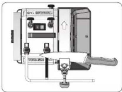
natural_image
Technical diagram of a mechanical device with control panel and lever mechanism (no visible text or symbols)Abziehen
natural_image
Illustration of hands operating a mechanical device with arrows indicating motion (no text or symbols)natural_image
Illustration of hands operating a mechanical device with arrows indicating motion (no text or symbols)natural_image
Illustration of hands operating a mechanical device with a handle and valve (no text or symbols visible)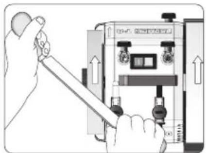
natural_image
Illustration of a hand using a tool to adjust or install an electrical meter device (no text or symbols visible)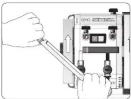
natural_image
Illustration of hands using a tool to adjust or install a device (no text or symbols visible)natural_image
Close-up of hands using a clamping tool to cut a metal component (no visible text or symbols)LANGE, DÜNNE MESSER
natural_image
Illustration of hands installing or adjusting a device panel inside a cabinet (no text or symbols visible)natural_image
Close-up of hands using a tool to adjust or install a mechanical component (no visible text or symbols)LA PLUPART DES COUTEAUX
natural_image
Illustration of three different kitchen utensils: a knife, a flat blade with handle, and a flat blade with curved handle (no text or symbols)natural_image
Two-panel illustration showing hands holding a device with internal components, no text or symbols present.natural_image
Hand holding a small mechanical component with a circular knob, no visible text or symbolsnatural_image
Illustration of hands using a tool to adjust or install a knife (no text or symbols visible)natural_image
Illustration of hands using a knife to adjust or install a piece of wood (no text or symbols visible)natural_image
Technical line drawing of a medical or surgical instrument with no visible text or symbols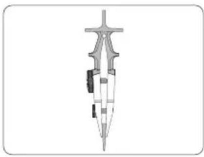
natural_image
Cross-sectional diagram of a mechanical or architectural component (no text or symbols visible)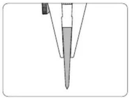
natural_image
Diagram of a pipette tip with a pointed tip and a handle (no text or symbols)natural_image
Pure line drawing of a pen writing on paper (no text or symbols)natural_image
Illustration of hands using a tool to apply a pen tip (no text or symbols visible)natural_image
Mechanical component diagram showing internal structure with two arrows indicating direction (no text or symbols)natural_image
Illustration of a pen writing on paper with an arrow indicating upward and downward motion (no text or symbols present)natural_image
Mechanical assembly diagram showing a wheel and attached components (no text or symbols visible)natural_image
Illustration of a pen writing on paper with an inset showing a cross-section (no text or symbols)natural_image
Illustration of hands operating a device with a downward arrow, no visible text or symbols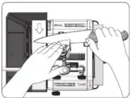
natural_image
Illustration of hands operating a device with a knife, no text or symbols visible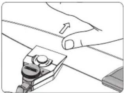
natural_image
Illustration of a hand using a tool to adjust or install a piece of paper (no text or symbols visible)natural_image
Simple line drawing of a curved, layered shape with no text or symbolsnatural_image
Illustration of hands installing or adjusting a component with a paper clip, no visible text or symbols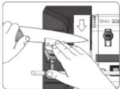
natural_image
Illustration of hands using a tool to adjust or install electronic components (no text or symbols visible)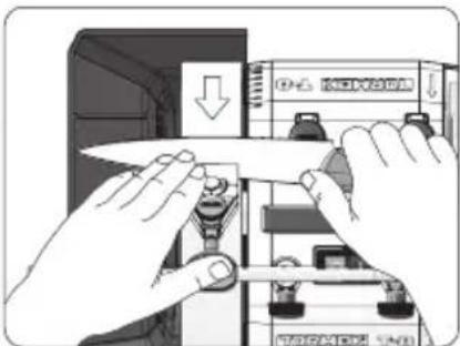
natural_image
Illustration of hands installing or adjusting a document on a device panel (no text or symbols visible)text_image
Diagram showing hands operating a mechanical device with a downward arrow and labeled components, likely illustrating a process or assembly.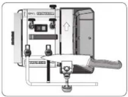
natural_image
Technical diagram of an electrical enclosure with control panel and door (no text or symbols visible)Démorfilage
natural_image
Illustration of hands operating a mechanical device with arrows indicating motion (no text or symbols)natural_image
Illustration of hands operating a mechanical device with arrows indicating motion (no text or symbols)natural_image
Illustration of hands operating a device with a glass and a handle, showing internal components (no text or symbols)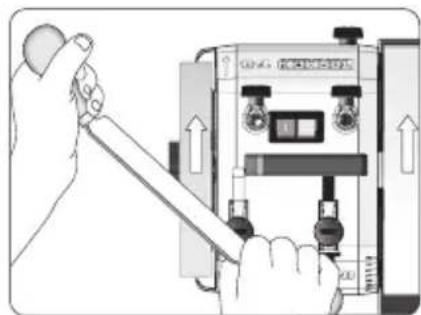
natural_image
Illustration of a hand using a tool to adjust or install an electrical control panel (no text or symbols visible)