what is the purpose of bracket A
Just bought a used Hitachi and just trying ti figure it out
Any idea also on where I can acquire a paper manual
Thks
Find the device manual for free C 10FSHC HITACHI in PDF.

1 question about this device. Answer the ones you know or ask your own.
Just bought a used Hitachi and just trying ti figure it out
Any idea also on where I can acquire a paper manual
Thks
Download the instructions for your Saw in PDF format for free! Find your manual C 10FSHC - HITACHI and take your electronic device back in hand. On this page are published all the documents necessary for the use of your device. C 10FSHC by HITACHI.
IMPROPER OR UNSAFE use of this power tool can result in death or serious bodily injury! This manual contains important information about product safety. Please read and understand this manual before operating the power tool. Please keep this manual available for other users and owners before they use the power tool. This manual should be stored in safe place.
DOUBLE INSULATION DOUBLE ISOLATION AISLAMIENTO DOBLE
Page
IMPORTANT SAFETY INFORMATION ....3
MEANINGS OF SIGNAL WORDS ....3
SAFETY 4
IMPORTANT SAFETY INSTRUCTIONS FOR
USING ALL POWER TOOLS 4
REPLACEMENT PARTS 8
USE PROPER EXTENSION CORD 8
PRACTICAL APPLICATIONS ....27
SAW BLADE MOUNTING AND DISMOUNTING ....37
MAINTENANCE AND INSPECTION ....39
SERVICE AND REPAIRS 41
PARTS LIST 126
Page
INFORMATIONS IMPORTANTES DE
SÉCURITÉ 42
SIGNIFICATION DES MOTS
D'AVERTISSEMENT 42
SECURITE 43
CONSIGNES DE SECURITE RELATIVES AUX
APPLICATIONS PRATIQUES 68
INSTALLATION ET RETRAIT DE LA LAME .....79
ENTRETIEN ET INSPECTION 81
SERVICE APRÈS-VENTE ET RÉPARATIONS .....83
LISTE DES PIECES ....126
Página
Read and understand all of the safety precautions, warnings and operating instructions in the Instruction Manual before operating or maintaining this power tool.
Most accidents that result from power tool operation and maintenance are caused by the failure to observe basic safety rules or precautions. An accident can often be avoided by recognizing a potentially hazardous situation before it occurs, and by observing appropriate safety procedures.
Basic safety precautions are outlined in the "SAFETY" section of this Instruction Manual and in the sections which contain the operation and maintenance instructions.
Hazards that must be avoided to prevent bodily injury or machine damage are identified by WARNINGS on the power tool and in this Instruction Manual.
NEVER use this power tool in a manner that has not been specifically recommended by HITACHI.
WARNING indicates a potentially hazardous situations which, if ignored, could result in death or serious injury.
CAUTION indicates a potentially hazardous situations which, if not avoided, may result in minor or moderate injury, or may cause machine damage.
NOTE emphasizes essential information.
READ ALL OF THE WARNINGS AND OPERATING INSTRUCTIONS IN THIS MANUAL BEFORE OPERATING OR MAINTAINING THIS TOOL:
WARNING: When using this electric tool, take all necessary precautions to minimize the risk of electric shock or other personal injury. In particular, always comply with the following safety rules:
ALWAYS SECURE THE WORKPIECE TO THE FENCE OR THE TABLE. Use clamps or a vise to hold the workpiece in place. It is safer than using your hand and it frees both hands to operate the tool.
NEVER OVERREACH. Always keep proper footing and balance when working with the tool.
⚠ WARNING: The following specific operating instructions must be observed when using this POWER TOOL in order to avoid injury:
6
When servicing use only identical replacement parts.
Repairs should be conducted only by a Hitachi authorized service center.
Make sure your extension cord is in good condition. When using an extension cord, be sure to use one heavy enough to carry the current your product will draw. An undersized cord will cause a drop in line voltage resulting in loss of power and overheating. Table shows the correct size to use depending on cord length and nameplate ampere rating. If in doubt, use the next heavier gage. The smaller the gage number, the heavier the cord.
MINIMUM GAGE FOR CORD SETS
| Total Length of Cord in Feet (Meter) | ||||
| 0 – 25(0 – 7.6) | 26 – 50(7.9 – 15.2) | 51 – 100(15.5 – 30.5) | ||
| Ampere Rating AWG | ||||
| More | Not More | |||
| Than | Than | |||
| 0 – 6 18 16 16 14 | ||||
| 6 – 10 18 16 14 12 | ||||
| 10 – 12 16 16 14 12 | ||||
| 12 – 16 14 12 Not Recommended | ||||

Avoid electrical shock hazard. Never use this tool with a damaged or frayed electrical cord or extension cord. Inspect all electrical cords regularly. Never use in or near water or in any environment where electric shock is possible.
8
To ensure safer operation of this power tool, HITACHI has adopted a double insulation design. "Double insulation" means that two physically separated insulation systems have been used to insulate the electrically conductive materials connected to the power supply from the outer frame handled by the operator. Therefore, either the symbol "☐" or the words and "Double insulation" appear on the power tool or on the nameplate.
Although this system has no external grounding, you must still follow the normal ele safety precautions given in this Instruction Manual, including not using the power tool in wet environments.
To keep the double insulation system effective, follow these precautions:
* Only HITACHI AUTHORIZED SERVICE CENTER should disassemble or assemble this power tool, and only genuine HITACHI replacement parts should be installed.
* Clean the exterior of the power tool only with a soft cloth moistened with soapy water and dry thoroughly.
* Never use solvents, gasoline or thinners on plastic components; otherwise the plastic may dissolve.
NOTE: The information contained in this Instruction Manual is designed to assist you in the safe operation and maintenance of the power tool. Some illustrations in this Instruction Manual may show details or attachments that differ from those on your own power tool.
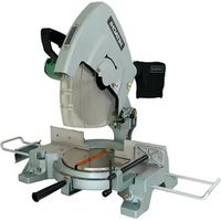
MODEL C10FSHC
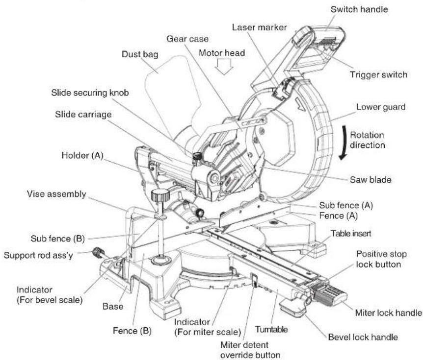
Fig. 1
10
English
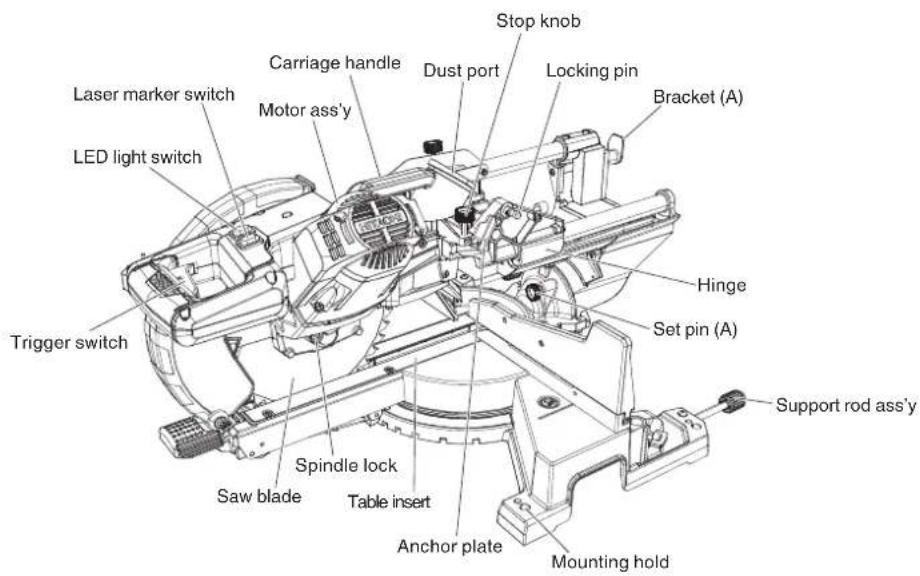
Fig. 2
SPECIFICATIONS
| Item Model C 10FSHC | ||||
| Motor Type Series commutator motor | ||||
| Power source Single-phase AC 60Hz | ||||
| Voltage (Volts) 120 | ||||
| Full-load current (Amp) 15 | ||||
| Laser Marker Maximum output | <5mW CLASS IIIa Laser Product | |||
| Wave length 630 - 660 nm | ||||
| Laser medium Laser Diode | ||||
| Applicable saw blade | Outside Dia. 10" (255 mm)Hole Dia. 5/8" (15.9 mm) | |||
| No load speed 3,200/min | ||||
| Max. sawing dimension | Head Turntable Max. sawing dimension | |||
| Miter | 0 | 0 | (With anchor plate)Max. HeightMax. Width(Without anchor plate)Max. HeightMax. Width | |
| 0 | Left 45° orRight 45° | (With anchor plate)Max. HeightMax. Width(Without anchor plate)Max. HeightMax. Width | ||
| 0 | Left 55° | (With anchor plate)Max. HeightMax. Width(Without anchor plate)Max. HeightMax. Width | ||
| 0 | Right 60° | (With anchor plate)Max. HeightMax. Width(Without anchor plate)Max. HeightMax. Width | ||
| Bevel Left 45° | 0 | (With anchor plate)Max. HeightMax. Width(Without anchor plate)Max. HeightMax. Width | 1-3/4" (45 mm)11-1/2" (292 mm)1-5/8" (41 mm)12-1/2" (318 mm) | |
| Right 45° | 0 | (With anchor plate)Max. HeightMax. Width(Without anchor plate)Max. HeightMax. Width | ||
| Compound | Left 45° | Left 45° orRight 45° | (With anchor plate)Max. HeightMax. Width(Without anchor plate)Max. HeightMax. Width | |
| Right 45° | Left 45° orRight 45° | (With anchor plate)Max. HeightMax. Width(Without anchor plate)Max. HeightMax. Width | ||
| Right 45° | Left 45° orRight 45° | (With anchor plate)Max. HeightMax. Width(Without anchor plate)Max. HeightMax. Width | ||
| Miter sawing range | Left 0° - 55° Right 0° - 60° | |||
| Bevel sawing range | Left 0° - 48° Right 0° - 48° | |||
| Compound sawing range | Left (Bevel) 0° - 45°, Left (Miter) 0° - 45° | |||
| Right (Bevel) 0° - 45°, Right (Miter) 0° - 45° | ||||
| Net weight | 45.6 lbs. (20.7 kg) | |||
| Cord | 2 Conductor type cable 6ft. (1.8 m) | |||
WARNING: Accessories for this power tool are mentioned in this Instruction Manual. The use of any other attachment or accessory can be dangerous and could cause injury or mechanical damage.
STANDARD ACCESSORIES
| ① Vise Assembly (1 piece) For how to use, refer to page 28. | ② Dust bag (1 piece) For how to use, refer to page 15. |
| ③ 13 mm Wrench (1 piece) | ④ Support rod ass'y (2 pieces) 5 mm screw (2 pieces) |
Fig. 3
NOTE: Accessories are subject to change without any obligation on the part of the HITACHI.
Wood and aluminum sash.
Make the following preparations before operating the power tool:
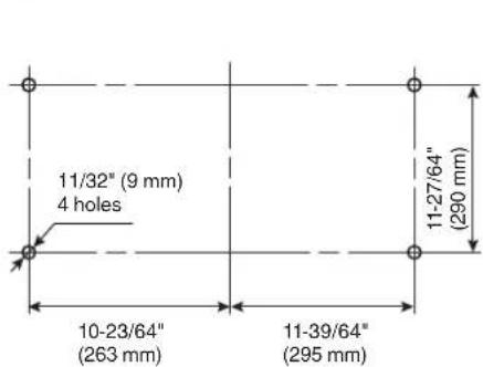
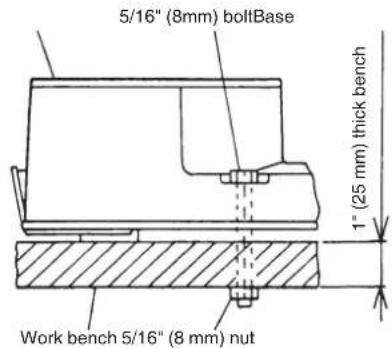
Fig. 4
Attach the power tool to a level, horizontal work bench in accordance with Fig. 4. Select 5/16" (8 mm) diameter bolts suitable in length for the thickness of the work bench. Bolt length should be at least 1-9/16" (40 mm) plus the thickness of the work bench. For example, use 2-9/16" (65 mm) or larger bolts for a 1" (25 mm) thick work bench.
The support rod ass'y attached to the rear of the base helps stabilize the power tool.
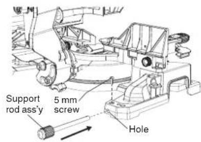
Fig. 5
Installing the support rod ass'y
Insert one support rod ass'y into the hole located at the rear of the base and push it in as far as it will go.
Thread the 5 mm screw into the hole next to the mounting hold.
Firmly tighten the 5 mm screw with a screwdriver.
Repeat the above steps for installing the other support rod ass'y.
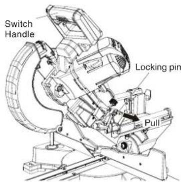
Fig. 6
When the power tool is prepared for shipping, its main parts are secured by a locking pin.
Press the handle slightly down and pull out the locking pin to disengag the cutting head.
NOTE: Lowering the handle slightly will enable you to disengage the locking pin more easily and safely. The lock position of the locking pin is for carrying and storage only.

Install the dust bag onto the dust port on the miter saw. Fit the connecting tube of dust bag and the dust port together.
To empty the dust bag, pull out the dust bag assembly from dust port. Open zipper on underside of bag and empty into waste container. Check frequently and empty the dust bag before it gets full.
NOTE: The dust bag should be angled toward the right side of the saw for best results. This will also avoid any interference during the saw operation.
Fig. 7
⚠️CAUTION: Empty the dust bag frequently to prevent the duct and the lower guard from becoming clogged.
Sawdust will accumulate more quickly than normal during cutting.
⚠ WARNING: Do not use this saw to cut and/or sand metals. the hot chips or sparks may ignite saw dust from the bag material.
(Attach the vise assembly as shown in Fig. 1, Fig. 2 and Fig. 25.)
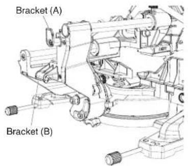
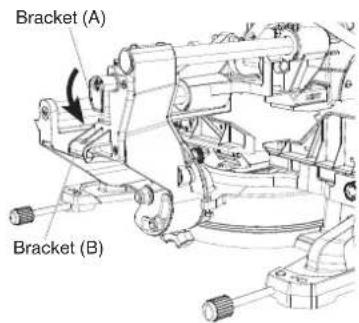
Fig. 8-a Fig. 8-b
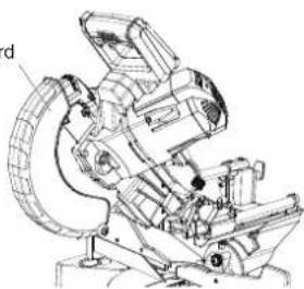
For convenience and to prevent damage to the power cord when the miter saw is not in use or is in transportation, there are two brackets at the rear side of the slide carriage for winding the cord. (Fig. 8-a)
NOTE: To rapidly release the power cord, turn the upper bracket (A) 180°. It will release the cord. (Fig. 8-b)
⚠ WARNING: Never connect the power tool unless the available AC power source is of the same voltage as that specified on the nameplate of the tool. Never connect this power tool to a DC power source.
⚠ WARNING: If the power cord is connected to the power source with the trigger switch turned ON the power tool will start suddenly and can cause a serious accident.
Confirm that the saw blade is free of cracks or other visible damage.
Using the supplied 13 mm wrench, tighten the 8 mm bolt on the saw blade spindle to secure the saw blade. For details, see Fig. 44-a, Fig. 44-b, Fig. 44-c and Fig. 44-d in the section on "SAW BLADE MOUNTING AND DISMOUNTING".
16
Lower guard
Lower guard is designed to protect the operator from coming into contact with the saw blade during operation of the tool.
Always check that the lower guard moves smoothly and covers the saw blade properly.
Fig. 9
After installing the saw blade, confirm that the spindle lock has been returned to the released position before using the power tool (see Fig. 2).
To prevent overheating, accidental stopping or intermittent operation, confirm that the power cord plug fits properly in the electrical receptacle and does not fall out after it is inserted. Repair or replace the receptacle if it is faulty.
Repair or replace the power cord if an inspection indicates that it is damaged
Always wear eye protection with side shields that meets the requirements of ANSI Standard Z87.1. Ordinary eyeglasses do not provide adequate protection because they do not contain impact resistant safety glass.
This tool is equipped with an electric brake which will typically stop the blade within 5 seconds after the trigger switch is released.
Occasionally, there will be a delay in the brake engaging which will result in a longer blade stopping time. On rare occasions, the brake may not engage at all and the saw blade will coast to a stop.
If the brake fails to engage frequently, depress and release the trigger switch to turn the tool on and off 4 or 5 times. If the brake still does not engage, have the tool serviced at a Hitachi authorized service center.
Always confirm that the saw blade has completely stopped before raising it from the workpiece.
The brake is not a substitute for a properly functioning lower guard. Check the function of the lower guard before each use. Serious personal injury may occur if the lower guard does not move smoothly and cover the blade properly.
⚠ WARNING: Please be aware of the reaction of the Motor Head (Fig.1) when the brake is activated. Braking causes the Motor Head to jerk downward and the user should be prepared for this reaction, especially when the trigger switch is released before the blade is completely down. Failure to be familiar with, and prepared for, the operational characteristics of the tool may cause serious injury.
After confirming that no one is standing behind, the power tool start and confirm that no operating abnormalities exist before attempting a cutting operation.
For precise cutting, rotate the saw blade and check for deflection to confirm that the blade is not noticeably unstable; otherwise vibrations might occur and cause an accident.
[Right angle cutting] Fig. 10-a
[Left bevel angle cutting] Fig. 10-b
[Right bevel angle cutting] Fig. 10-c
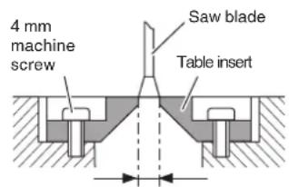
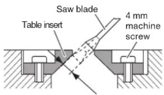
Table inserts are installed on the turntable. When shipping the tool from the factory, the table inserts are so fixed that the saw blade does not contact them. The burr of the bottom surface of the workpiece is remarkably reduced, if the table insert is fixed so that the gap between the side surface of the table insert and the saw blade will be minimum. Before using the tool, eliminate this gap in accordance with the following procedure.
Loosen the three 4 mm machine screws, then secure the left side table insert and temporarily tighten the 4 mm machine screws of both ends. Then fix a workpiece (about 7-7/8" (200 mm) wide) with the vise assembly and cut it off. After aligning the cutting surface with the edge of the table insert, securely tighten the 4 mm machine screws of both ends. Remove the workpiece and securely tighten the 4 mm center machine screw. Adjust the right hand table insert in the same way.
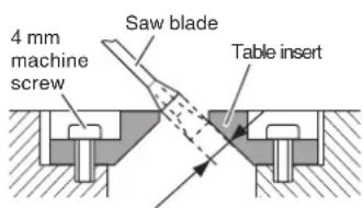
(2) Left and right bevel angle cutting
Adjust the table insert in the manner shown in Fig. 10-b and Fig. 10-c following the same procedure for right angle cutting.
⚠️ CAUTION: After adjusting the table insert for right angle cutting, the table insert will be cut to some extent if it is used for bevel angle cutting.
When bevel cutting operation is required, adjust the table insert for bevel angle cutting.
WARNING: The sub fence (A) must be extended when making any right angle bevel cut. Failure to extend the sub fence (A) will not allow enough space for the blade to pass through which could result in serious injury. At extreme miter or bevel angles the saw blade may also contact the fence.
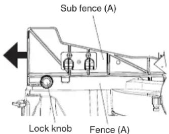
Fig. 11
This power tool is equipped with a sub fence (A).
In the case of direct angle cutting and left bevel angle cutting, use the sub fence (A). Then, you can realize stable cutting of the material with a wide back face.
When right angle cutting, loosen the lock knob, then slide the sub fence (A) outward, as shown in Fig. 11.
When you slide sub fence (A) outward, if enough space cannot be secured or the sub fence (A) comes into contact with other parts of the tool including the motor, fully remove sub fence (A) from fence (A). Also, make sure to remove the lock knob from fence (A).
NOTE: When transporting the saw, always secure the sub fence (A) in the collapsed position and lock it.
WARNING: The sub fence (B) must be extended when making any left angle bevel cut. Failure to extend the sub fence (B) will not allow enough space for the blade to pass through which could result in serious injury. At extreme miter or bevel angles the saw blade may also contact the fence.
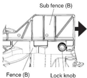
Fig. 12
This power tool is equipped with a sub fence (B). In the case of direct angle cutting and right bevel angle cutting, use the sub fence (B). Then, you can realize stable cutting of the material with a wide back face. When left angle cutting, loosen the lock knob, then slide the sub fence (B) outward, as shown in Fig. 12. When you slide sub fence (B) outward, if enough space cannot be secured or the sub fence (B) comes into contact with other parts of the tool including the lower guard, fully remove sub fence (B) from fence (B).
NOTE: When transporting the saw, always secure the sub fence (B) in the collapsed position and lock it.
WARNING: Always clamp or vise to secure the workpiece to the fence; otherwise the workpiece might be thrust from the table and cause bodily harm.
⚠ WARNING: To reduce the risk of injury, return slide carriage to the full rear position after each crosscut operation.
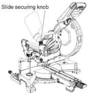
Fig. 13
For chop cutting operations on small workpieces, slide the cutting head assembly completely toward the rear of the unit and tighten the slide securing knob.
To cut wide boards up to 305 mm, the slide securing knob must be loosened to allow the cutting head slide freely.
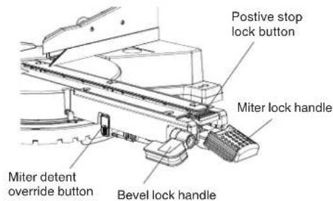
Fig. 14
If miter angles required are NOT one of the nine positive stops, the miter table can be locked at any angle between these positive stops by using the positive stop lock button and miter lock handle.
Unlock the miter table by lifting up the miter lock handle, grasp the miter lock handle and pressing down on the positive stop lock button to move the table to the desired angle, then release the positive stop lock button. Press down on the miter lock handle to lock the table in position.
20
The miter detent override button allows for the table to be micro adjusted, disengaging the positive detent stops feature. When a required miter angle is close to a positive detent stop, this override prevents the wedge on the miter arm from slipping into that detent slot on the base.
(1) Unlock the miter table by lifting up the miter lock handle.
(2) Press down on the positive stop locking button and press the miter detent override button in, then release the positive stop locking button while pressing the miter detent override in. The detent override is now engaged.
(3) Turn the table to the desired angle, secure the table at the desired angle by pressing the miter lock handle.
(4) To disengage the miter detent override button, press down again on the positive stop locking button.
⚠ WARNING: To ensure accurate cuts, alignment should be checked and adjustments made prior to use.
(1) Loosen bevel lock handle by lifting it up and tilting the cutting arm while pushing in the set pin (A) against the 0° bevel stop, please refer Fig. 15-a and 15-b. Tighten the bevel lock handle.
(2) Place a combination square on the miter table with the ruler against the table and the heel of the square against the saw blade as show in Fig. 15-a.
(3) If the blade is not 0^ to the miter table, loosen the three adjustment bolts at the rear of the unit with a 4 mm hex spanner, please refer Fig. 15-c. Unlock the bevel lock handle and adjust the cutting arm to zero degrees to the table. After alignment is achieved, tighten the three adjustment bolts and press down on the bevel lock handle to secure the cutting head.
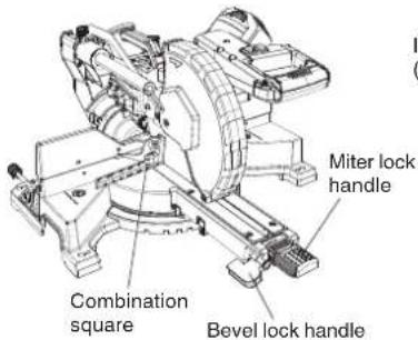
Fig. 15-a
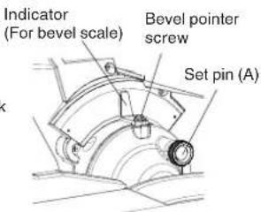
Fig. 15-b
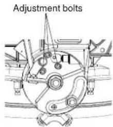
Fig. 15-c
(1) When the blade is exactly 90^ ( 0^ ) to the table, loosen the bevel pointer screw using a #2 Phillips screwdriver.
(2) Adjust Indicator to the "0" mark on the bevel scale and retighten the screw.
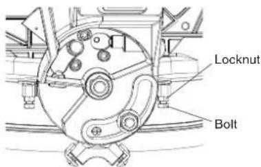
Fig. 16
(1) Fully extend the sub fence (B) completely to the left, and then pull the set pin (A) towards the front of the machine.
NOTE: When retracting the set pin (A), it may be necessary to shift the miter saw upper arm assembly to the left/right to release the holding pressure.
(2) Loosen the bevel lock handle and tilt the gear case completely to the left.
(3) Using a combination square, check to see if the blade is 45^ to the table.
(4) To adjust, tilt the gear case to 0^ , loosen the locknut, and turn the bolt in or out to increase or decrease the angle as shown in Fig. 16.
(5) Tilt the gear case back to the left, and recheck alignment.
(6) Repeat steps until the blade is 45^ to the table. Once alignment is achieved, tighten locknut and bevel lock handle when alignment is achieved.
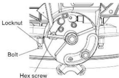
Fig. 17
(1) Set the miter angle to 0^ . Fully extend the sub fence (A) completely to the right, and then pull the set pin (A) towards the front of the machine.
NOTE: When retracting the set pin (A), it may be necessary to shift the mitre saw upper arm assembly to the left/right to release the holding pressure.
(2) Loosen the bevel lock handle and tilt the gear case completely to the right.
(3) Using a combination square, check to see if the blade is 45^ to the table.
(4) To adjust, tilt the gear case to 0^ , loosen the locknut, and turn the bolt in or out to increase or decrease the angle as shown in Fig. 17.
(5) Tilt the cutting arm back to the right, and recheck alignment.
(6) Repeat steps until the blade is 45^ to the table. Once alignment is achieved, tighten locknut and bevel lock handle when alignment is achieved.
(1) Set the mitre angle to 0^ . Fully extend both sub fences (A, B).
(2) Loosen the bevel lock handle, and tilt gear case to the 33.9° right bevel positive stop by pushing on the set pin (A) towards the rear of the machine.
(3) Using a combination square, check to see if the blade is 33.9^ to the table.
(4) To adjust, turn the hex screw in or out with a 3 mm spanner until the blade is 33.9^ to the table.
(5) Repeat the above steps and turn the hex screw for the 33.9° left bevel adjustment.
The slide compound miter saw scale can be easily read, showing miter angles from 0^ to 48^ to the left and right. The miter saw table has nine of the most common angle settings with positive stops at 0^ , 15^ , 22.5^ , 31.6^ , and 45^ . These positive stops position the blade at the desired angle quickly and accurately. Follow the process below for quickest and most accurate adjustments.
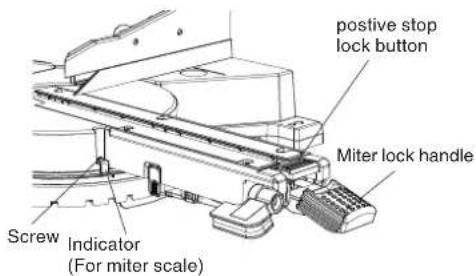
Fig. 18
Adjusting miter angles:
(1) Lift up on the miter lock handle to unlock the table.
(2) Move the table while pressing down on the positive stop lock button to align the pointer to the desired degree measurement.
(3) Lock the table into position by pressing down on the miter lock handle.
Indicator (For miter scale) adjustment:
(1) Move the table to the 0^ positive stop.
(2) Loosen the screw that holds the Indicator (For miter scale) with a Phillips screwdriver.
(3) Adjust the pointer to the 0^ mark and retighten the screw.
The maximum depth travel of the cutting head was set at the factory.
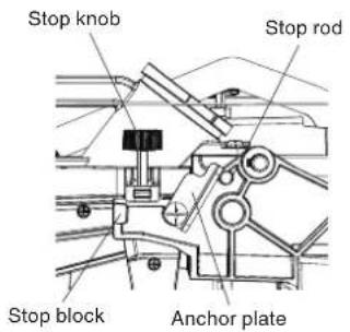
Fig. 19-a
(1) Setting the maximum width travel of the cutting head, follow the below steps: (Fig. 19-a)
Turn the stop knob counterclockwise until the stop knob is not protruding out of the stop block while moving the cutting head upward.
Rotate the anchor plate clockwise to touch the stop rod.
Recheck the blade depth by moving the cutting head front to back through the full motion of a typical cut along the control arm.
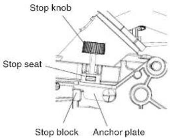
Fig. 19-b
(2) Setting the maximum height travel of the cutting head, follow the below steps: (Fig. 19-b) Turn the stop knob counterclockwise until the stop knob is not protruding out of the stop block while moving the cutting head upward. Rotate the anchor plate counterclockwise to touch the stop seat. Make sure the stop block touches the anchor plate completely.
The depth of cut can be preset for even and repetitive shallow cuts.
(1) Adjust the cutting head down until the teeth of the blade are at the desired depth.
(2) While holding the upper arm in that position, turn the stop knob until it touches the anchor plate.
(3) Recheck the blade depth by moving the cutting head front to back through the full motion of a typical cut along the control arm.
NOTE: If the anchor plate becomes loose, it can interfere with raising and lowering the cutting head. The anchor plate must be tightened in horizontal position as shown in Fig. 19-b.
⚠ WARNING: * For your own safety, never connect the plug to power source outlet until all the adjustment steps are complete and you have read and understood the safety and operational instructions.
* Your tool is equipped with a laser guide using a Class IIIa laser guide. The laser guide allows you to preview the saw blade path on the workpiece to be cut before starting the miter saw. This laser guide is powered by the transformed alternating current supply directly through the power lead. The saw must be connected to the power source and the laser on/off switch must be turned on for the laser line to show.
(1) Avoid direct eye contact
⚠ WARNING: * Laser radiated when laser guide is turned on. Avoid direct eye contact.
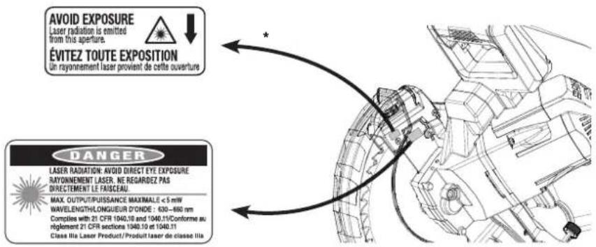
Fig. 20
CAUTION: * Use of controls or adjustments or performance of procedures may result in hazardous radiation exposure. * The use of optical instruments with this product will increase eye hazard.
⚠ WARNING: Do not attempt to repair or disassemble the laser. If unqualified persons attempt to repair this laser product, serious injury may result. Any repair required on this laser product should be performed by a qualified service dealer.
(2) Checking laser line alignment
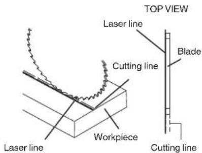
Fig. 21
(a) Set the saw to a 0^ miter and 0^ bevel setting.
(b) Use a combination square to mark a 90^ angled running across the top and down the front of a board. This line will serve as the pattern line to adjust the laser. Place the board on the saw table.
(c) Carefully lower the saw head down to align the saw blade with the pattern line. Position the saw blade to the left, side of the "pattern line" depending on your preference for the laser line location. Lock the board in place with the hold-down clamp.
(d) With the saw plugged in, turn on the laser guide. Your saw has been preset with the laser line to the left side of the blade.
⚠ WARNING: When making laser line adjustments, keep fingers away from the ON/OFF trigger switch to prevent accidental starting and possible serious injury.
(e) Slide the cutting head forward enough so that the laser line is visible on the front of the board.
(f) Looking at the front of the board, if the laser line is not parallel to the "pattern line" please follow the instructions listed below under "Front line" paragraph.
(g) Looking at the top of the board, if the laser line is not parallel to the "pattern line" please follow the instructions listed below under "Top line" paragraph.
NOTE: If the laser line is not visible on the front of a board, lower the cutting head until the laser line is visible.
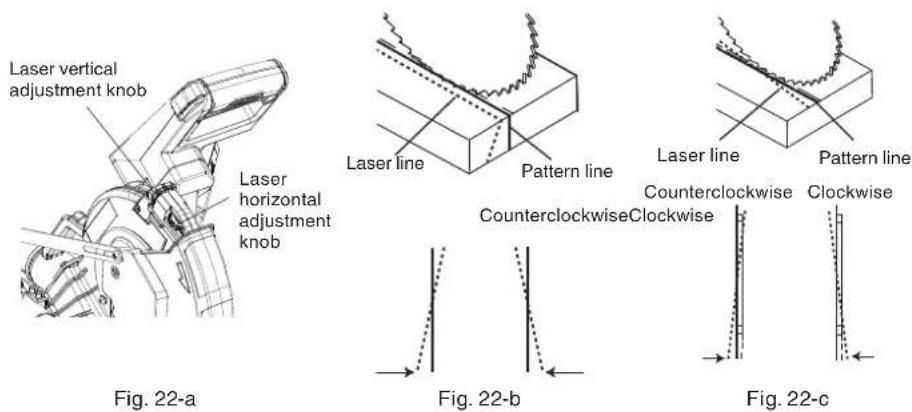
(3) Adjusting the position of the laser line
Front line
If the laser line is angled from pattern line of front side, turn the laser vertical adjustment knob to align the laser line parallel with pattern line. (Fig. 22- b)
Top line
If the laser line is angled from pattern line of top side, turn the laser horizontal adjustment knob to align the laser line parallel with pattern line. (Fig. 22-c)
NOTE: When adjusting the front line and top line, turning the adjustment knob too much will result in the laser reflecting off of the saw blade to produce two laser lines.
NOTE: After performing the above adjustments, visually check that both the front and top laser lines are parallel with pattern line.
WARNING: * To avoid personal injury, never remove or place a workpiece on the table while the tool is being operated. * Never place your limbs inside of the line next to warning sign while the tool is being operated. This may cause hazardous conditions (see Fig. 23).
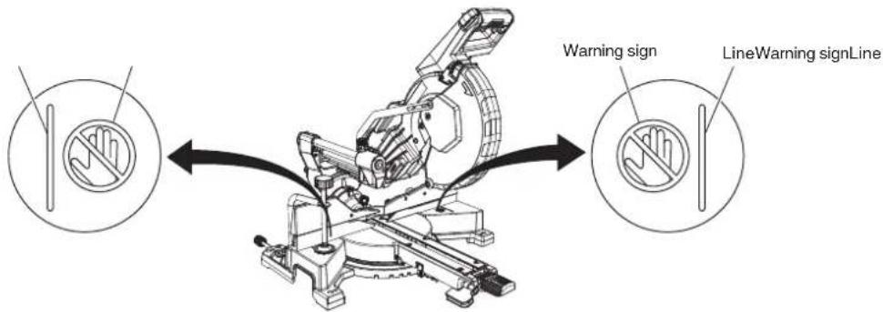
Fig. 23
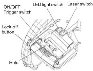
Fig. 24
(1) Turning the saw on This miter saw is equipped with trigger switch (2). With the lock-off button pressed, squeeze the trigger switch to turn the miter saw ON. Release the trigger switch to turn the saw OFF.
(2) Turning the laser guide / LED light on Press the laser switch to turn it ON, and press again to turn it OFF. Press the the LED light switch to turn it ON, and press again to turn it OFF.
⚠ WARNING: Make the ON/OFF switch childproof. Insert a padlock, or chain with padlock, through the hole in the trigger and lock the tool's switch, preventing children and other unqualified users from turning the machine on.
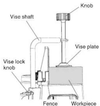
Fig. 25
(1) The vise assembly can be mounted on the base.
(2) Turn the upper knob and securely fix the workpiece in position (Fig. 25).

Fig. 26
(1) As shown in Fig. 26 the width of the saw blade is the width of the cut. Therefore, slide the workpiece to the right (viewed from the operator's position) when length ⑥ is desired, or to the left when length ④ is desired. If a laser marker is used, align the laser line with the left side of the saw blade, and then align the ink line with the laser line.
(2) Once the saw blade reaches maximum speed, push the handle down carefully until the saw blade approaches the workpiece.
(3) Once the saw blade contacts the workpiece, push the handle down gradually to cut into the workpiece.
(4) After cutting the workpiece to the desired depth, turn the power tool OFF and let the saw blade stop completely before raising the handle from the workpiece to return it to the full retract position.
⚠️ CAUTION: Increased pressure on the handle will not increase the cutting speed. On the contrary, too much pressure may result in overload of the motor and/or decreased cutting efficiency.
⚠ WARNING: * Confirm that the trigger switch is turned OFF and the power plug has been removed from the receptacle whenever the tool is not in use. * Always turn the power off and let the saw blade stop completely before raising the handle from the workpiece. If the handle is raised while the saw blade is still rotating, the cut-off piece may become jammed against the saw blade causing fragments to scatter about dangerously. * Every time one cutting or deep-cutting operation is finished, turn the trigger switch off, and check that the saw blade has stopped. Then raise the handle, and return it to the full retract position. * Be absolutely sure to remove the cut material from the top of the turntable, and then proceed to the next step. * Continued cutting operation can result in overload of the motor. Touch the motor and if it's hot, stop your cutting operation at once and rest for 10 minutes or so, and then restart your cutting operation.
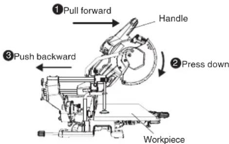
Fig. 27
(1) Workpieces up to 3-1/2" (89 mm) high and 11-1/2" (292 mm) wide: Loosen the slide securing knob (see Fig. 1), grip the handle and slide the saw blade forward. Then press down on the handle and slide the saw blade backward to cut the workpiece as indicated in Fig. 27. This facilitates cutting of workpieces of up to 3-1/2" (89 mm) in height and 11-1/2" (292 mm) in width.
(2) Workpieces up to 2-1/2" (64 mm) high and 12-1/2" (318 mm) wide: Workpieces of up to 2-1/2" (64 mm) in height and up to 12-1/2" (318 mm) in width can be cut in the same manner as described in paragraph 4-(1) above on page 29.
* If the handle is pressed down with excessive or lateral force, the saw blade may vibrate during the cutting operation and cause unwanted cutting marks on the workpiece, thus reducing the quality of the cut.
Accordingly, press the handle down gently and carefully.
* In slide cutting, gently push the handle back (rearwards) in a single, smooth operation.
Stopping the handle movement during the cut will cause unwanted cutting marks on the workpiece.
* For slide cutting, follow the procedures indicated above in Fig. 27. Forward slide cutting (toward the operator) is very dangerous because the saw blade could kick upward from the workpiece. Therefore, always slide the handle away from the operator.
* Always return the carriage to the full rear position after each crosscut operation in order to reduce the risk of injury.
* Never put your hand on the side handle during the cutting operation because the saw blade comes close to the miter lock handle when the motor head is lowered.
The sub fences must be extended when making any bevel cut. Failure to extend the sub fences will not allow enough space for the blade to pass through which could result in serious injury. At extreme miter or bevel angles the saw blade may also contact the fence.
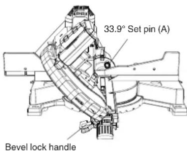
Fig. 28
(1) When a bevel cut is required, loosen the bevel lock handle.
(2) Tilt the cutting head to the desired angle while pulling the set pin (A), as shown on the bevel scale.
(3) The blade can be positioned at any angle, from a 90^ straight cut ( 0^ on the scale) to a 45^ . Tighten the bevel lock handle to lock the cutting head in position. Positive stops are provided at 0^ , 33.9^ and 45^ .
NOTE: The saw comes with a 33.9° set pin (A) for setting up crown moulding cuts when the angle of the walls equals 90°.
(4) Turn the laser guide on and position the workpiece on the table for pre-alignment of your cut.
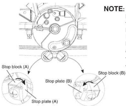
NOTE: If 48^ left bevel is necessary, slide the bevel stop plate (A) clockwise away from the stop block (A) to achieve 48^ left bevel.
If 48^ right bevel is necessary, slide the bevel stop plate (B) counterclockwise away from the stop block (B) to achieve 48^ right bevel.
Also, use anchor plate. (see Fig. 19-b)
Fig. 29
⚠ WARNING: When the workpiece is secured on the left or right side of the blade, the short cut-off portion will come to rest on the right or left side of the saw blade. Always turn the power off and let the saw blade stop completely before raising the handle from the workpiece.
If the handle is raised while the saw blade is still rotating, the cut-off piece may become jammed against the saw blade causing fragments to scatter about dangerously.
When stopping the bevel cutting operation halfway, start cutting after pulling back the motor head to the initial position.
Starting from halfway, without pulling back, causes the lower guard to be caught in the cutting groove of the workpiece and to contact the saw blade.
⚠️ CAUTION: * If not tightened firmly enough the motor head might suddenly move or slip, causing injuries. Be sure to tighten the motor head section enough so it will not move.
* Always check that the bevel lock handle is secured and the motor head is clamped. If you attempt angle cutting without clamping the motor head, then the motor head might shift unexpectedly causing injuries.
(1) Push the bevel set pin (A) in towards the rear of the machine.
(2) Loosen the bevel locking handle.
(3) Tilt the cutting head until the set pin (A) stops the bevel angle at 33.9^ on the bevel scale.
(4) Tighten the bevel locking handle to lock the cutting head in position. (see Fig. 28)
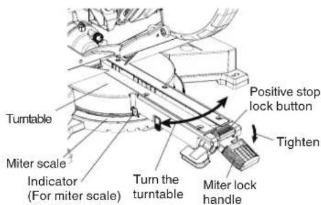
Fig. 30
(1) Unlock the miter table by lifting up on the miter lock handle.
(2) While pressing down on the positive stop lock button, grasp the miter lock handle and rotate the table left or right to the desired angle.
(3) Once the desired miter angle is achieved, release the positive stop lock button and press down on the miter lock handle to secure the table into position.
(4) If the desired miter angle is NOT one of the nine positive stops noted below, please see the Miter detent override button section on page 21.
(5) Turn the laser guide on and position the workpiece on the table for pre-alignment of your cut.
CAUTION: Always check that the miter lock handle is secured and the turntable is clamped. If you attempt angle cutting without clamping the turntable, then the turntable might shift unexpectedly causing injuries.
NOTE: * Positive stops are provided at the right and left of the 0° center setting, at 15°, 22.5°, 31.6° and 45° settings.
Check that the miter scale and the tip of the indicator are properly aligned.
* Operation of the saw with the miter scale and indicator out of alignment will result in poor cutting precision.
Compound cutting can be performed by following the instructions in 5 to 7 above. For maximum dimensions for compound cutting, refer to "SPECIFICATIONS" table on page 12.
⚠️ CAUTION: Always secure the workpiece with the right or left hand and cut it by sliding the round portion of the saw backwards with the left hand.
It is very dangerous to rotate the turntable to the left during compound cutting because the saw blade may come into contact with the hand that is securing the workpiece.
In case of compound cutting (angle + bevel) by left bevel, extend the sub-fence (B) fully before cutting operation.
In case of compound cutting (angle + bevel) by right bevel, extend the sub-fence (A) fully before cutting operation.
Please confirm that sub fence (A) (B) does not interfere with other parts before attempting compound cutting. If there is any interference, remove either sub fence (A) or (B).
32
Fig. 31 shows two common crown molding types having angles of (θ) 38° and 45°.
For the typical crown molding fittings, see Fig. 32.
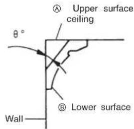
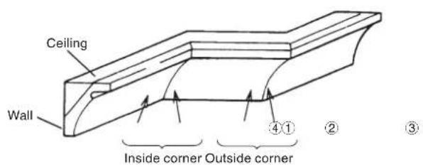
Fig. 31 Fig. 32
The table below shows the miter angle and the bevel angle settings that are ideal for the two crown molding types.
NOTE: For convenience, positive stops are provided for the miter setting (left and right 31.6°) positions.
If the turntable has been set to either of the angles described, move the turntable adjusting miter lock handle a little to the right and left to stabilize the position and to properly align the miter angle scale and the tip of the indicator before the operation starts.
Tighten the bevel lock handle and check that the position is stable and that the bevel angle scale and the tip of the indicator are properly aligned. Then tighten the clamp lever.
| Type of Crown Molding | To process crown molding at positions 1 and 4 in Fig. 32. | To process crown molding at positions 2 and 3 in Fig. 32. | ||
| Miter Angle Setting | Bevel Angle Setting | Miter Angle Setting | Bevel Angle Setting | |
| 45^ Type right 35.3^ left 30^ left 35.3^ | left 30^ | |||
| 38^ Type | right 31.6^ | left 33.9^ | left 31.6^ | left 33.9^ |
(1) Setting to cut crown moldings at positions ① and ④ in Fig. 32 (see Fig. 33; tilt the motor head to the left):
① Turn the turntable to the right and set the Miter Angle as follows:
* For 45° type crown moldings: 35.3°
* For 38° type crown moldings: 31.6°
② Tilt the motor head to the left and set the Bevel Angle as follows:
* For 45° type crown moldings: 30°
* For 38° type crown moldings: 33.9°
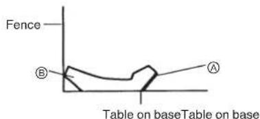
③ Position the crown molding so that the upper surface (A in Fig. 31) contacts the fence as indicated in Fig. 35.
(2) Setting to cut crown moldings at positions ② and ③ in Fig. 32 (see Fig. 34; tilt the head to the left):
① Turn the turntable to the left and set the Miter Angle as follows:
* For 45° type crown moldings: 35.3°
* For 38° type crown moldings: 31.6°
② Tilt the head to the left and set the Bevel Angle as follows:
* For 45° type crown moldings: 30°
* For 38° type crown moldings: 33.9°
③ Position the crown molding so that the lower surface (® in Fig. 31) contacts the fence as in Fig. 36.
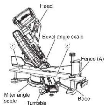
Fig. 33
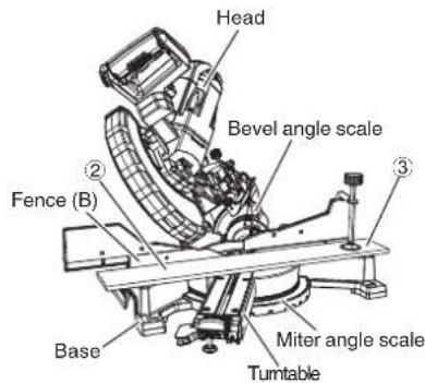
Fig. 34
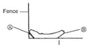
Fig. 35 Fig. 36
(3) Setting to cut crown moldings at positions ① and ④ in Fig. 32 (see Fig. 37; tilt the head to the right):
① Turn the turntable to the right and set the Miter Angle as follows:
* For 45° type crown moldings: 35.3°
* For 38° type crown moldings: 31.6°
② Tilt the head to the right and set the Bevel Angle as follows:
* For 45° type crown moldings: 30°
* For 38° type crown moldings: 33.9°
③ Position the crown molding so that the upper surface (® in Fig. 31) contacts the fence as indicated Fig. 39.
(4) Setting to cut crown moldings at positions ② and ③ in Fig. 32 (see Fig. 38; tilt the head to the right):
① Turn the turntable to the left and set the Miter Angle as follows:
* For 45° type crown moldings: 35.3°
* For 38° type crown moldings: 31.6°
② Tilt the head to the right and set the Bevel Angle as follows:
* For 45° type crown moldings: 30°
* For 38° type crown moldings: 33.9°
③ Position the crown molding so that the lower surface (A in Fig. 31) contacts the fence as in Fig. 40.
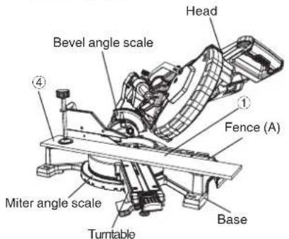
Fig. 37
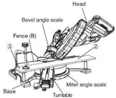
Fig. 38
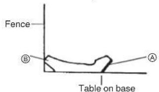
Fig. 39
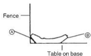
Fig. 40
WARNING: Always firmly clamp or vise to secure the crown molding to the fence; otherwise the crown molding might be thrust from the table and cause bodily harm.
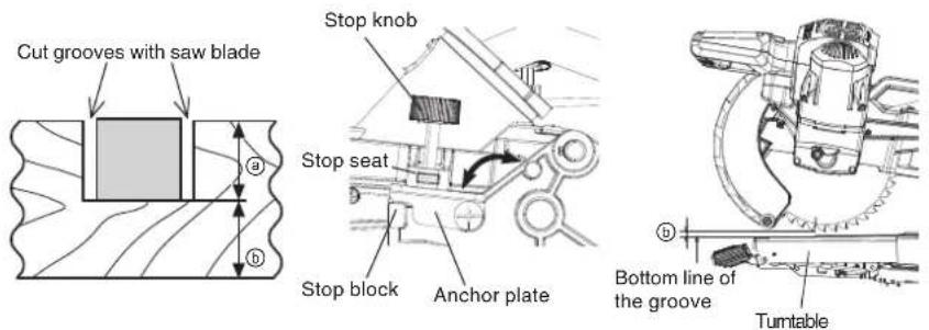
Fig. 41
Fig. 42
Grooves in the workpiece can be cut as indicated in Fig. 41 by adjusting the stop knob.
(1) Turn the anchor plate on the direction shown in Fig. 42.
Lower the motor head, and turn the stop knob by hand. (Where the head of the stop knob contacts the anchor plate.)
(2) Adjust to the desired cutting depth by setting the distance between the saw blade and the surface of the turntable (see ⑥ in Fig. 42).
NOTE: When cutting a single groove at either end of the workpiece, remove the unneeded portion with a chisel.
Materials such as aluminum sash can easily deform when tightened too much in a vise assembly. This will cause inefficient cutting and possible overload of the motor.
When cutting such materials, use a wood plate to protect the workpiece as shown in Fig. 43-a. Set the wood plate near the cutting section.
When cutting aluminum materials, coat the saw blade with cutting oil (non-combustible) to achieve smooth cutting and a fine finish.
In addition, in case of a U-shaped workpiece, use the wood plate as shown in Fig. 43-b to ensure stability in the lateral direction, and clamp it near the cutting section of the workpiece and tighten it using both the vise assembly and the clamp available in the market.
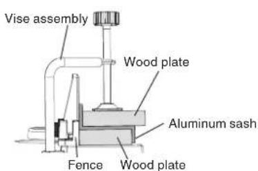
Fig. 43-a
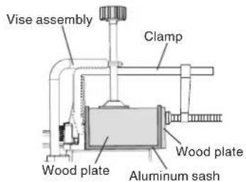
Fig. 43-b
⚠ WARNING: * To prevent an accident or personal injury, always turn off the trigger switch and disconnect the power plug from the receptacle before removing or installing a saw blade. If cutting work is done in a state where the 8 mm bolt is not sufficiently tightened, the 8 mm bolt can get loose, the blade can come off, and the lower guard can get damaged, resulting in injuries.
Also, check that the 8 mm bolts are properly tightened before plugging the power plug into the receptacle.
* If the 8 mm bolts are attached or detached using tools other than the 13 mm wrench (standard accessory), excessive or improperly tightening occurs, resulting in injury.
(1) Unplug the power cord from the outlet.
(2) Raise the cutting head to the upright position and slide the cutting head completely toward the rear of the unit and tighten the slide securing knob.
(3) Raise the lower guard to the up position.
(4) Remove the cover plate screw with a Phillips screwdriver.
(5) Place the blade end spanner over the 8 mm bolt.
(6) Locate the spindle lock on the motor.
(7) Press the spindle lock, holding it in firmly while turning the blade clockwise. The spindle lock will then engage and lock the arbour. Continue to hold the spindle lock, while turning the spanner clockwise to loosen the 8 mm bolt.
(8) Remove the 8 mm bolt, washer (B) and the blade. Do not remove the washer (A).
NOTE: If the spindle lock cannot be easily pressed in to lock the spindle, turn the 8 mm bolt with 13 mm wrench (standard accessory) while applying pressure on the spindle lock.
The saw blade spindle is locked when the spindle lock is pressed inward.
NOTE: Pay attention to the pieces removed, noting their position and direction they face. Wipe the washer (B) clean from any sawdust before installing a new blade.
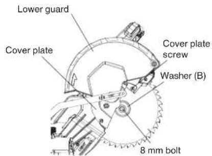
Fig. 44-a
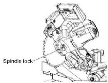
Fig. 44-b
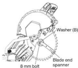
Fig. 44-c
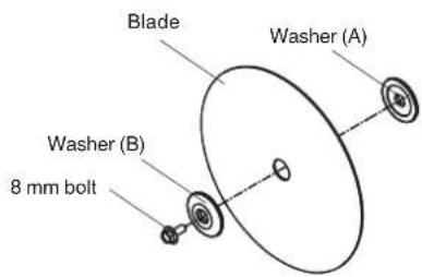
Fig. 44-d
WARNING: When mounting the saw blade, confirm that the rotation indicator mark on the saw blade and the rotation direction of the lower guard (see Fig. 1) are properly matched.
CAUTION: * Confirm that the spindle lock has returned to the retract position after installing or removing the saw blade. * Tighten the 8 mm bolt so it does not come loose during operation. Confirm the 8 mm bolt has been properly tightened before the power tool is started.
⚠ WARNING: Unplug the mitre saw before changing/installing the blade.
(1) Select a 255 mm blade, making sure the rotation arrow on the blade matches the clockwise rotation arrow on the lower guard, and the blade teeth are pointing downward.
(2) Place the blade, washer (B) against the blade. Thread the 8 mm bolt in a counterclockwise direction.
NOTE: Make sure the flats of the blade collars are engaged with the flats on the arbour shaft. Also, the flat side of the blade collar must be placed against the blade.
(3) Place the blade spanner on the 8 mm bolt.
(4) Press the spindle lock, holding it in firmly while turning the blade counterclockwise. When it engages, continue to press the spindle lock in, while tightening the 8 mm bolt securely.
(5) Replace the cover plate screw and tighten with a Phillips screwdriver.
(6) Rotate the cover plate and lower guard back to its original position.
(7) Verify the operation of the lower guard does not bind or stick.
(8) Be sure the spindle lock is released so the blade turns freely.
⚠️ CAUTION: Never attempt to install saw blades larger than 10" (255 mm) in diameter. Always install saw blades that are 10" (255 mm) in diameter or less.
⚠ WARNING: To avoid an accident or personal injury, always confirm that the trigger switch is turned OFF and the power plug has been disconnected from the receptacle before performing any maintenance or inspection of this tool.
Always replace the saw blade immediately upon the first sign of deterioration or damage. A damaged saw blade can cause personal injury and a worn saw blade can cause ineffective operation and possible overload to the motor.
CAUTION: Never use a dull saw blade. When a saw blade is dull, its resistance to the hand pressure applied by the tool handle tends to increase, making it unsafe to operate the power tool.
The carbon brushes in the motor are expendable parts.
If the carbon brushes become excessively worn, motor trouble might occur.
Therefore, inspect the carbon brushes periodically and replace them when they have become worn to the wear limit line as shown in Fig. 45.
Also, keep the carbon brushes clean so that they will slide smoothly within the brush holders.
Remove the two securing screws and the motor rear cover from the motor. Carefully remove the brush cap on the side of the motor. Third, pull out the carbon brush and replace. The ears on the metal end of the assembly go in the same hole the carbon part fits into. Last, tighten the cap snugly, but do not overtighten. Repeat above procedure for the carbon brush located on the other side of the motor.
NOTE: When replacing the carbon brushes, use only Hitachi carbon brushes having "463" of Code No. (see Fig. 45). If you use other carbon brushes, the electric brake will not operate.

Fig. 45
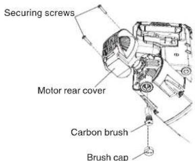
Fig. 46
Winding of the motor is said to be the heart of this tool. Exercise utmost caution not to damage the winding by exposing it to wash oil or water.
NOTE: Accumulation of dust and the like inside the motor can result in a malfunction.
After using the motor for 50 hours or so, carry out no-load running, and blow in the dry air from a wind hole at the motor's rear. Such action is effective to discharge dust and the like.
Regularly inspect each component of the power tool for looseness.
Re-tighten screws on any loose part.
⚠ WARNING: To prevent personal injury, never operate the power tool if any components are loose.
Before each use of the tool, test the lower guard (see Fig. 9) to assure that it is in good condition and that it moves smoothly.
Never use the tool unless the lower guard operates properly and it is in good mechanical condition.
After operation of the tool has been completed, check that the following has been performed:
(1) Trigger switch is in OFF position,
(2) Power plug has been removed from the receptacle,
When the tool is not in use, keep it stored in a dry place out of the reach of children.
Lubricate the following sliding surfaces once a month to keep the power tool in good operating condition for a long time (see Fig. 1 and Fig. 2). Use of machine oil is recommended.
40
* Rotary portion of hinge
* Rotary portion of vise assembly
* Rotary portion of holder (A)
Periodically remove chips, dust and other waste material from the surface of the power tool, especially from the inside of the lower guard with a damp, soapy cloth. To avoid a malfunction of the motor, protect it from contact with oil or water.
If the laser line becomes invisible due to chips and the like adhered onto the window of the laser marker's light-emitting section, wipe and clean the window with a dry cloth or a soft cloth moistened with soapy water, etc.
A: HKU#
B: I.D. No.
C: Description
D: Size
E: Q'ty

CAUTION: Repair, modification and inspection of Hitachi Power Tools must be carried out by a Hitachi Authorized Service Center.
This Parts List will be helpful if presented with the tool to the Hitachi Authorized Service Center when requesting repair or other maintenance. In the operation and maintenance of power tools, the safety regulations and standards prescribed in each country must be observed.
Hitachi Power Tools are constantly being improved and modified to incorporate the latest technological advancements.
Accordingly, some parts (i.e. code numbers and/or design) may be changed without prior notice.
All quality power tools will eventually require servicing or replacement of parts because of wear from normal use. To assure that only authorized replacement parts will be used and that the double insulation system will be protected, all service (other than routine maintenance) must be performed by an AUTHORIZED HITACHI POWER TOOL REPAIR CENTER ONLY.
NOTE: Specifications are subject to change without any obligation on the part of HITACHI.
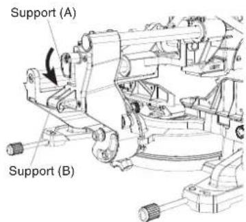
Fig. 8-a Fig. 8-b

A: HKU#
B: I.D. No.
C: Description
D: Taille
E: Qté

Fig. 32
126
SLIDE COMPOUND MITER SAW MODEL NO. C 10FSHC PARTS LIST
| A | B | C | D | E | A | B | C | D | E |
| 372093 083Z CORD CLAMP 1 372499 32RA NUT CHUCK M6*1.0 T=6 | 2 | ||||||||
| 372441 0CES COMPRESSION SPRING 1 372500 32RC NUT CHUCK | M12*1.75 T=12 | 1 | |||||||
| 372442 0CPD CENTER BOLT | 1 372501 33N7 | FLAT WASHER | 6'16-1.5 | 2 | |||||
| 372443 0D9A ANCHOR BLOCK | 1 372502 34BN COMPRESSION SPRING 1 | ||||||||
| 372444 0DT4 ROLLING WHEEL | 2 372503 387B | HEX. SOC. TRUSS HD. & WASHER ASSY | M6*1.0-12 | 2 | |||||
| 372445 0DT7 BEARING | 2 372504 39XD COMPRESSION SPRING 1 | ||||||||
| 372446 0DVJ BLADE WRENCH | 1 372505 3ADS HEX. NUT | M6*1.0 T=52 | |||||||
| 726478 0J4F FLAT WASHER | 8'16-2.5 | 1 | 339796 3ADZ | NUT CHUCK | M10*1.5, T=10 | 1 | |||
| 327352 0J66 FLAT WASHER | 4'10-1 | 1 | 339832 3AE3 | FLAT WASHER | 10'20-3 | 1 | |||
| 949434 0J7K FLAT WASHER | 3/8*29/32-5/64 | 1 | 372508 3AZ7 | CR. RE. PAN HD. SCREW | M5*0.8-16 | 3 | |||
| 372450 0JA7 EXTERNAL TOOTH LOCK WASHER | 6 | 3 3 | 372509 3BKD HINGE | 1 | |||||
| 372018 0JAZ WAVE WASHER | 2 | 372510 3DJ8 | LOCATING BAR | 1 | |||||
| 327354 0JB0 WAVE WASHER | 2 3 | 372511 3DJ9 | FRAME ENDCAP | 1 | |||||
| 372453 0JBG DISC SPRING WASHER | 12 | 1 | 372512 3DJA | WASHER BEARING | 1 | ||||
| 372454 0JE7 C-RING | 1 372513 3DJG SPACER | 2 | |||||||
| 372455 0JFB SELF-LOCKING RING | 2 | 372514 3DJL | SET PLATE | 1 | |||||
| 372456 0JMN O-RING | 1 | 372515 3DJP | SLIDE CARRIAGE ASSY | 1 | |||||
| 372050 0JMP O-RING | 1 | 372516 3DJR | SLIDE CARRIAGE | 1 | |||||
| 372458 0JNR O-RING ROD | 2 | 372517 3DKF | SHAFT-PIVOT | 1 | |||||
| 372459 0JPE HEX. HD. BOLT | M6*1.0-20 | 2 | 372518 3DKJ | TORSION SPRING | 1 | ||||
| 372460 0JUK HEX. SOC. HD. CAP BOLT | M6*1.0-16 | 1 | 372519 3DMM | BEARING COVER | 3 | ||||
| 968247 0JX9 HEX. SOC. SET SCREW | M6*1.0-10 | 1 | 372520 3DTM | SHAFT SLEEVE | 1 | ||||
| 726318 0K05 HEX. SOC. TRUSS HD. SCREW | M8*1.25-20 | 4 3 | 372521 3DTZ RUBBER PAD | 1 | |||||
| 726539 0K2B HEX SOC. HD. CAP SCREW | M6*1.0-16 | 1 | 372522 3DWT | INSERT | 1 | ||||
| 372464 0K4S CR. RE. TRUSS HD. SCREW | M5*0.8-16 | 2 | 372523 3DXM | LINEAR MOTION BEARING | 1 | ||||
| 372465 0K5E CR. RE. COUNT HD. SCREW | M6*1.0-25 | 1 | 372524 3FJH | SET PLATE | 1 | ||||
| 372466 0KD8 CR. RE. PAN HD. SCREW | M4*0.7-12 | 1 | 372525 3FJQ | WRENCH SET | 1 | ||||
| 949236 0KDH CR. RE. PAN HD. SCREW | M5*0.8-8 | 1 | 372730 3FQM | SPACER | 1 | ||||
| 726615 0KQW LOCK NUT | M5*0.8,T=5 | 1 | 372526 3FVK | LASER_COVER | 1 | ||||
| 339840 0KQX NUT | M6*1.0,T=6 | 1 | 372527 3FVL | COVERLASER_COVER | 1 | ||||
| 372073 0KQY LOCK NUT | M8*1.25,T=8 | 1 | 372528 3FVM | LEVELING PAD | 1 | ||||
| 314474 0KR3 LOCK NUT | M6*1.0 T=6 1 372529 3FVQ ADJUSTABLE NUT | 1 | |||||||
| 372472 0KTP CABLE CLAMP | 1 372530 3G3T | MITER DETENT OVERRIDE BUTTON | 1 | ||||||
| 726627 0KUW TERMINAL | 4 | 372531 3G4S | VISE ASSY | 1 | |||||
| 372474 10KD ROLL PIN | 2 | 372532 3GGH | SPECIAL BOLT | 1 | |||||
| 372475 22A4 LOCKING CABLE TIE | 1 | 372533 3GGQ | ARM MITER COVER | 1 | |||||
| 372476 23NX GUARD-CORD | 1 | 372534 3GGS | BRACKET(B) | 1 | |||||
| 372477 25B1 CR. RE. TRUSS HD. SCREW | M5*0.8-25 | 1 | 372535 3GGT | BRACKET(A) | 1 | ||||
| 372478 27PF COMPRESSION SPRING | 1 | 372536 3GJ8 | INDICATOR (FOR BEVEL SCALE) | 1 | |||||
| 372479 2B7H HEX. SOC. SET SCREW | 2 3 | 372537 3H38 | LOCK-OFF BUTTON | 1 | |||||
| 372480 2E35 TRIGGER SWITCH | 1 | 372538 3H3E | TORSION SPRING | 1 | |||||
| 372481 2F39 LOCKING PIN | 1 372539 3H9P POWER CABLE | 1 | |||||||
| 372024 2JHZ CR. RE. PAN HD. TAPPING SCREW | M5*0.8-12 | 3 | 372540 3H9U | LEAD WIRE ASSY | 1 | ||||
| 372483 2JTR INSULATING SLEEVE | 1 | 372541 3HHM | CR. RE. COUNT HD. SCREW | M4*0.7-8 | 4 | ||||
| 372484 2MOS LIMIT SWITCH | 1 | 372542 3HHT | CR. RE. TRUSS HD. SCREW | M6*1.0-8 | 1 | ||||
| 372485 2MX6 CR. RE. PAN HD. SCREW & WASHER | M6*1.0-20 | 4 | 372543 3HHU | CR. RE. TRUSS HD. SCREW | M5*0.8-6 | 3 | |||
| 372486 2NAH CR. RE. TRUSS HD. SCREW | M4*0.7-8 | 1 | 372544 3HHX | CR. RE. PAN HD. TAPPING SCREW | M4*18-16 | 3 | |||
| 372487 2RXR CR. RE. PAN HD. SCREW | M4*0.7-8 | 1 | 372545 3HHZ | CR. RE. PAN HD. TAPPING SCREW | M4*18-25 | 1 | |||
| 372488 2RYJ CR. RE. PAN HD. TAPPING SCREW | M4*16-20 | 3 3 | 372546 3HJ0 | CR. RE. PAN HD. TAPPING SCREW | M3*24-8 | 4 | |||
| 372489 2VEP SHAFT | 1 372547 3HJ3 | CR. RE. PAN HD. ROUND NECK SCREW | M6*1.0-12 | 1 | |||||
| 372490 2VH6 LINEAR MOTION BEARING | 2 | 372548 3HJ5 | CR. RE. PAN HD. SCREW | M5*0.8-6 | 1 | ||||
| 372491 2VN7 BLANKET WASHER | 4 | 372549 3HJ7 | CR. RE. PAN HD. SCREW | M5*0.8-8 | 8 | ||||
| 372492 2VS0 LEAD WIRE ASSY | 1 | 372550 3HJ8 | CR. RE. PAN HD. SCREW | M5*0.8-55 | 2 | ||||
| 372493 2WK0 COMPRESSION SPRING | 1 | 372551 3HJA | CR. RE. PAN HD. SCREW | M5*0.8-25 | 1 | ||||
| 372494 2WX6 WASHER (A)/(B) | 2 | 372552 3HJB | CR. RE. PAN HD. SCREW | M5*0.8-10 | 6 | ||||
| 372495 2XSF CR. RE. COUNT HD. TAPPING SCREW | M5*16-8 | 3 | 372553 3HJF | HEX. SOC. SET SCREW | M6*1.0-16 | 2 | |||
| 372496 2YR6 SPRING GUARD | 1 | 372554 3HJG | HEX. SOC. SET SCREW | M6*1.0-10 | 2 | ||||
| 372497 306G BUSHING | 1 | 372555 3HJH | HEX. SOC. HD.CAP SCREW | M5*0.8-40 | 2 | ||||
| 372498 31VX CR. RE. TRUSS HD. ROUND NECK SCREW | M6*1.0-14 | 1 | |||||||
SLIDE COMPOUND MITER SAW MODEL NO. C 10FSHC PARTS LIST
| A | B | C | D | E | A | B | C | D | E |
| 372556 | 3HJP | HEX. SOC. TRUSS HD. & WASHER ASS'Y | M6*1.0-16 2 | 3725 | 97 | 3TU2 COVER PLATE 1 | |||
| 372557 | 3HJU | HEX. WASHER HD. BOLT M8*1.25-20 1 | 372598 | 3TU3 | LOWER GUARD 1 | ||||
| 372558 | 3HJW | HEX. NUT M5*0.8,T=4 1 | 372599 | 3TU4 | BRACING PLATE | 1 | |||
| 372559 | 3HK1 | FLAT WASHER | 12^21-1 | 1 | 372600 | 3TU6 | CABLE COVER | 1 | |
| 372560 | 3HK2 | FLAT WASHER | 5^14-1 | 1 | 372601 | 3TU7 | LAMP SOCKET | 1 | |
| 372561 | 3HK3 | FLAT WASHER | 6^12-1 | 2 | 372602 | 3TU8 | SWITCH HANDLE(RIGHT) | 1 | |
| 372562 | 3HKB | HEX. SOC. SET SCREW | M6*1.0-12 | 1 | 372603 | 3TU9 | SWITCH HANDLE(LEFT) | 1 | |
| 372563 | 3J7N | CR.RE. PAN HD. TAPPING SCREW | M4*16-16 | 1 | 372604 | 3TWF | CONTROLLER ASS'Y | 1 | |
| 372564 | 3JE7 | HEX. SOC. HD. CAP SCREWS | M5*0.8-20 | 1 | 372605 | 3TWK | LED LIGHT | 1 | |
| 372565 | 3VUA | CAUTION LABEL | 1 | 372606 | 3TWL | INSERT | 1 | ||
| 372566 | 3KOU | ANCHOR PLATE | 1 | 372607 | 3TWW | MOTOR ASS'Y | 1 | ||
| 372567 | 3KOV | CR. RE. TRUSS HD. ROUND NECK SCREW | M6*1.0-10 1 | 372608 | 3U2U | STOP KNOB | 1 | ||
| 372568 | 3KJ1 | INSULATING SLEEVE | 8.5-50 | 1 | 372609 | 3U6Q | LABLE LINE COVER | 1 | |
| 372569 | 3M9D | SET PLATE | 1 | 372610 | 3UG6 | TABLE INSERT | 2 | ||
| 372570 | 3MAR | SUPPORT ROD PAD | 2 | 372611 | 3UMM | LABEL | 1 | ||
| 372571 | 3MAS | SUPPORT ROD | 2 | 372612 | 3UMN | MITER SCALE | 1 | ||
| 372572 | 3MFB | ALLEN BOLT | M5*0.8-35 | 1 | 372613 | 3UMQ | CAUTION LABEL | 1 | |
| 372573 | 3R9Z | CR. RE. PAN HD. TAPPING SCREW | M5*0.8-35 1 | 3726 | 14 | 3UMR | CAUTION LABEL | 1 | |
| 372574 | 3S85 | SLIDE PLATE | 1 | 372615 | 3UMS | CAUTION LABEL | 1 | ||
| 372575 | 3S9R | NEEDLE ROLLER | 8 | 372616 | 3UMT | WARNING LABEL | 1 | ||
| 372576 | 3SG0 | INDICATOR (FOR MITER SCALE) | 1 | 372617 | 3UMU | WARNING LABEL | 1 | ||
| 372577 | 3TMD | HEX. SOC. HD. CAP SCREW | M6*1.0-14 3 | 3726 | 18 | 3UMV | WARNING LABEL | 1 | |
| 372578 | 3TRD | DUST BUG | 1 | 372619 | 3UMW | INSTRUCTIONS MANUAL | 1 | ||
| 372579 | 3TTF | BASE | 1 | 372620 | 3UN5 | CABLE SHIELD | 1 | ||
| 372580 | 3TTG | FENCE | 1 | 372621 | 3UNA | LASER ASS'Y | 1 | ||
| 372581 | 3TTH | SUB FENCE(B) | 1 | 372622 | 3V10 | STOP PLATE(A) | 1 | ||
| 372582 | 3TTJ | SUB FENCE(A) | 1 | 372623 | 3V11 | STOP PLATE(B) | 1 | ||
| 372583 | 3TTK | CLAMP BOLT | 1 | 372624 | 3V19 | HOLDER(A) | 1 | ||
| 372584 | 3TTL | LOCK KNOB | 2 | 372625 | 3V1R | CR. RE. TRUSS HD. ROUND NECK SCREW | M5*0.8-12 2 | ||
| 372585 | 3TTM | SLIDE SECURING KNOB | 1 | 372626 | 3VAC | LASER STICKER | 1 | ||
| 372586 | 3TTN | VISE LOCK KNOB | 2 | 372627 | 3VAD | WARNING LABEL | 1 | ||
| 372587 | 3TTP | TURN TABLE | 1 | 372628 | 3VAE | TILTING SCALE | 1 | ||
| 372588 | 3TTQ | POSITIVE STOP LOCK BUTTON | 1 | 372629 | 3VKC | ROLL PIN | 1 | ||
| 372589 | 3TTR | MITER LOCK HANDLE | 1 | 372630 | 3VLV | CARRIAGE HANDLE | 1 | ||
| 372590 | 3TTS | BEVEL LOCK HANDLE | 1 | 372631 | 3VMT | BUSH | 4 | ||
| 372591 | 3TTT | PLUNGER HANDLE | 1 | 372632 | 3VN4 | SAW BLADE | 1 | ||
| 372592 | 3TTV | SPECIAL NUT | 1 | 372633 | 3VQA | LED/LASER SWITCH ASS'Y | 2 | ||
| 372593 | 3TTW | LOCATING BAR | 1 | 372634 | 3VQB | CAUTION LABEL | 1 | ||
| 372594 | 3TTY | LOCKING ROD | 1 | 372635 | 3VTE | STOP PLATE | 1 | ||
| 372595 | 3TTZ | BRACKET STOP | 1 | 372635 | Y43S | CR. RE. TRUSS HD. ROUND NECK SCREW | M6*1.0-15 1 | ||
| 372596 | 3TU1 | LEVER | 1 | ||||||

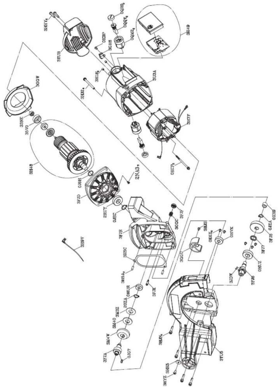
SLIDE COMPOUND MITER SAW MODEL NO. C 10FSHC SCHEMATIC
130
SLIDE COMPOUND MITER SAW MODEL NO. C 10FSHC PARTS LIST
| A | B | C | D | E |
| 372389 | 0HUR | BALL BEARING 1 | ||
| 372390 | 0HUZ | BALL BEARING 1 | ||
| 372391 | 0HVK | BALL BEARING 1 | ||
| 326905 | 0HX9 | NEEDLE BEARING 1 | ||
| 372393 | 0J6H | FLAT WASHER 15.02*19.2-11 | ||
| 317578 | 0JEA | C-RING 1 | ||
| 726512 | 0JEC | C-RING 1 | ||
| 372396 | 0JG7 | PARALLEL KEY 1 | ||
| 372397 | 0K6X | CR. RE. TRUSS HD. SCREW M4*0.7-65 | ||
| 372398 | 0KBP | CR. RE. PAN HD. TAPPING SCREW | M4*18-81 | |
| 372399 | 0KCP | CR. RE. PAN HD. TAPPING & WASHER SCREW | M5*12-60 | 2 |
| 326910 | 0QM2 | BRUSH HOLDER ASS'Y | 27*26.5 | 2 |
| 372085 | 0QQT | CARBON BRUSH | 2 | |
| 372402 | 0QR0 | BRUSH CAP | 2 | |
| 372403 | 20ZA | C-RING | 1 | |
| 372404 | 2NA3 | CR. RE. TRUSS HD. SCREW | M5*.8-10 | 3 |
| 372405 | 2RUY | BALL BEARING 1 | ||
| 372406 | 33NE | MAGNET | 1 | |
| 372407 | 35V0 | BEARING BUSHING | 1 | |
| 372408 | 3FJ6 | CUTTER SHAFT | 1 | |
| 372409 | 3FJ7 | COLLAR | 1 | |
| 372410 | 3FJ8 | HELIX GEAR | 1 | |
| 372411 | 3FJA | GEAR SHAFT | 1 | |
| 372412 | 3FJD | FRONT HOUSINT | 1 | |
| 372413 | 3FJE | SPINDLE LOCK 1 | ||
| 372414 | 3FJF | LOCK KNOB | 1 | |
| 372415 | 3FJR | GEAR BOX | 1 | |
| 372416 | 3GGC | COMPRESSION SPRING | 1 | |
| 372417 | 3GGU | OIL CAP | 1 | |
| 372418 | 3GGW | FLOW GUIDE | 1 | |
| 372419 | 3GH6 | HALL SENSOR ASS'Y | 1 | |
| 372420 | 3H48 | ARMATURE ASS'Y | 1 | |
| 372421 | 3H49 | CONTROLLER ASS'Y | 1 | |
| 372422 | 3H5A | NEEDLE ROLLER | 2 | |
| 372423 | 3H5C | OIL PAPER | 1 | |
| 372424 | 3H7F | FIELD ASS'Y | 1 | |
| 372425 | 3H9V | LEAD WIRE ASS'Y | 1 | |
| 372426 | 3HHY | CR. RE. PAN HD. TAPPING SCREW | M5*16-25 | 2 |
| 372427 | 3HJ2 | CR. RE. PAN HD. SCREW & WASHER | M5*0.8-60 | 4 |
| 372428 | 3HJN | HEX. SOC. HD. CAP SCREWS | M5*0.8-25 | 4 |
| 372429 | 3HJS | HEX. SOC. TRUSS HD. SCREW | M4*0.7-61 | |
| 372430 | 3HK5 | FLAT WASHER | 5*16-2 | 1 |
| 372431 | 3HLH | HEX. SOC. SET SCREW | M5*0.8-62 | |
| 372432 | 3HYZ | HEX. SOC. HD. CAP BOLT | M5*0.8-10 | 1 |
| 372433 | 3JDW | PARALLEL KEY | 1 | |
| 372434 | 3M3Z | CENTER SHAFT WASHER | 1 | |
| 372435 | 3M40 | BUMPER | 1 | |
| 372436 | 3M4W | STRAIGHT BEVEL GEAR | 1 | |
| 372437 | 3TU5 | GEAR CASE | 1 | |
| 372438 | 3TUB | MOTOR REAR COVER | 1 | |
| 372439 | 3U3A | MOTOR COVER | 1 |
Some dust created by power sanding, sawing, grinding, drilling, and other construction activities contains chemicals known to the State of California to cause cancer, birth defects or other reproductive harm. Some examples of these chemicals are:
- Lead from lead-based paints,
- Crystalline silica from bricks and cement and other masonry products, and
- Arsenic and chromium from chemically-treated lumber.
Your risk from these exposures varies, depending on how often you do this type of work. To reduce your exposure to these chemicals: work in a well ventilated area, and work with approved safety equipment, such as those dust masks that are specially designed to filter out microscopic particles.
Minato-ku, Tokyo 108-6020, Japan
Distributed by
PO Box 970
Braselton, GA 30517
450 Export Blvd. Unit B,
Mississauga ON L5S 2A4
706
Code No. C99231261
Printed in China