C 15FB - Saw HITACHI - Free user manual and instructions
Find the device manual for free C 15FB HITACHI in PDF.

User questions about C 15FB HITACHI
0 question about this device. Answer the ones you know or ask your own.
Ask a new question about this device
Download the instructions for your Saw in PDF format for free! Find your manual C 15FB - HITACHI and take your electronic device back in hand. On this page are published all the documents necessary for the use of your device. C 15FB by HITACHI.
USER MANUAL C 15FB HITACHI
natural_image
Technical line drawing of a mechanical cutting tool assembly (no text or symbols)INSTRUCTION MANUAL AND SAFETY INSTRUCTIONS
WARNING
Improper and unsafe use of this power tool can result in death or serious bodily injury! This manual contains important information about product safety. Please read and understand this manual before operating the power tool. Please keep this manual available for others before they use the power tool.
MODE D'EMPLOI ET INSTRUCTIONS DE SECURITE
⚠ AVERTISSEMENT
IMPORTANT INFORMATION ....3
MEANINGS OF SIGNAL WORDS....3
SAFETY
IMPORTANT SAFETY INSTRUCTIONS
FOR USING ALL POWER TOOLS ....3
REPLACEMENT PARTS 6
USE PROPER EXTENSION CORD....6
DOUBLE INSULATION FOR
AND DISMOUNTING ....16
MAINTENANCE AND INSPECTION ....17
SERVICE AND REPAIRS 18
TABLE DES MATIERES
Français
Page
INFORMATIONS IMPORTANTES ....19
SIGNIFICATION DES MOTS D'AVERTISSEMENT ..... 19
SECURITE
CONSIGNES DE SÉCURITÉ RELATIVES AUX OUTILS
ÉLECTRIQUES 19
PIECES DE RECHANGE....22
UTILISER LE CORDON DE RALLONGE
APPROPRIÉ 23
DOUBLE ISOLATION POUR UN
FONCTIONNEMENT PLUS SUR 23
UTILISATION ET ENTRETIEN
NOM DES PIÈCES 24
Page
SPÉCIFICATIONS 25
APPLICATIONS....26
PRÉPARATION AVANT L'UTILISATION .....26
AVANT L'UTILISATION ....27
AVANT LA COUPE 28
APPLICATIONS PRATIQUES ....30
INSTALLATION ET RETRAIT DE LA LAME .... 32
ENTRETIEN ET INSPECTION....33
SERVICE APRÈS-VENTE ET RÉPARATIONS .....34
ÍNDICE
Español
Página
Read and understand all of the operating instructions, safety precautions and warnings in the Manual before operating or maintaining this power tool.
Most accidents that result from tool operation and maintenance are caused by the failure to observe basic safety rules or precautions. An accident can often be avoided by recognizing a potentially hazardous situation before it occurs and by observing appropriate safety procedures.
Basic safety precautions are outlined in the SAFETY section of this manual and in the sections which contain the operation and maintenance instructions.
Hazards that must be avoided to prevent bodily injury or machine damage are identified by WARNINGS on the tool and in this Manual.
Never use this tool in a manner that has not been specifically recommended by HITACHI, unless you first confirm that the planned use will be safe for you and others.
MEANINGS OF SIGNAL WORDS
⚠ WARNING: indicates a potentially hazardous situation which, if ignored, could result in serious personal injury.
CAUTION: indicates a hazardous situation which, if ignored, could result in a moderate personal injury, or could cause machine damage.
NOTE emphasizes essential information.
SAFETY
IMPORTANT SAFETY INSTRUCTIONS FOR USING ALL POWER TOOLS
READ ALL OF THE WARNINGS AND OPERATING INSTRUCTIONS IN THIS MANUAL BEFORE OPERATING OR MAINTAINING THIS TOOL:
⚠ WARNING: When using this electric tool, take all necessary precautions to minimize the risk of electric shock or other personal injury. xIn particular, always comply with the following safety rules:
- ALWAYS KEEP GUARDS IN PLACE and in working order.
- ALWAYS REMOVE ADJUSTING KEYS AND WRENCHES BEFORE STARTING TOOL. Always confirm that all keys and adjusting wrenches have been removed from the tool before it is turned on.
- ALWAYS KEEP WORK AREA CLEAN. Avoid injuries by not cluttering the work areas and work benches.
-
NEVER USE TOOL IN HAZARDOUS ENVIRONMENTS. Never use the power tool in damp or wet places and never expose it to rain. Always keep the work area well lighted.
-
NEVER PERMIT CHILDREN OR OTHERS TO LOITER NEAR THE WORK AREA. Keep all people (especially children) away from the work area. Always unplug unattended tools and keep the work place tamper-proof by installing locks on the doors and on the master switches. Always remove the lock-off button from the tool and store it in a secure place, when the tool is not in use.
-
NEVER FORCE THE TOOL. It will do the job better and more safely if it is operated at the rate for which it was designed.
-
ALWAYS USE THE RIGHT TOOLS. Never force a tool or an attachment to do a job for which it was not designed.
-
ALWAYS WEAR PROPER APPAREL WHEN WORKING WITH THE TOOL. Never wear loose clothing, gloves, neckties, rings, bracelets or other jewelry which may get caught in the moving parts. Always wear non-slip footwear, preferably with steel toes. Wear protective hair covering to contain long hair.
-
ALWAYS USE EYE PROTECTION WHEN WORKING WITH THE TOOL TO PREVENT EYE INJURY. Ordinary eyeglasses do not provide adequate protection because the lenses are not made of safety glass. Also, use a face mask for additional safety and wear a dust mask if the cutting operation produces dust.
-
ALWAYS SECURE THE WORKPIECE TO THE FENCE OR THE TABLE. Use clamps or a vise to hold the workpiece in place. It is safer than using your hand and it frees both hands to operate the tool.
-
NEVER OVERREACH. Always keep proper footing and balance when working with the tool.
-
ALWAYS MAINTAIN TOOLS WITH CARE. Always keep tools sharp and clean for the best and safest performance. Always follow instructions for lubricating the tool and for changing accessories.
-
ALWAYS DISCONNECT THE TOOL before servicing and before changing blades or other accessories.
-
NEVER RISK UNINTENTIONAL STARTING WHEN PLUGGING IN THE TOOL. Always confirm that the switch is in the OFF position before inserting the power plug into the receptacle.
-
ALWAYS USE RECOMMENDED ACCESSORIES ONLY WHEN OPERATING THIS TOOL. Consult this instruction manual for descriptions of recommended accessories. To avoid personal injuries, use only recommended accessories in conjunction with this tool.
-
NEVER STAND ON THE TOOL. Prevent serious injury by not tipping the tool and by not risking unintentional contact with the saw blade.
-
ALWAYS CHECK FOR DAMAGED PARTS BEFORE USING THE TOOL. Always check the guard and all other components for damage before using the tool to assure that they will function properly. Check all moving parts for proper alignment, freedom from binding and other conditions that might affect proper operation. Always repair or replace any damaged guards or other damaged components before using the tool.
-
ALWAYS CONFIRM THE ROTATION DIRECTION OF THE BLADE BEFORE USING THE TOOL. Always feed work into the tool against the rotation direction of the blade in order to prevent possible injury.
-
NEVER LEAVE THE TOOL RUNNING WHILE UNATTENDED. TURN POWER OFF. Do not leave tool until it comes to a complete stop. Always turn the power off when the tool is not in use. Always unplug the power cord when the tool is not in use.
-
This tool was not designed to be used for mass-production applications and should not be used in mass-production environments.
-
When servicing this tool, use only authorized replacement parts.
-
Apply 115 volts AC only to this tool. Applying the wrong voltage or applying DC power can cause the POWER TOOL to operate improperly and cause serious personal injury or damage to the tool.
-
Never raise the saw blade from the workpiece until it has first come to a complete stop.
-
Always use outboard stands to provide support for long workpieces that overhang the table of the slide compound saw.
-
POLARIZED PLUGS To reduce the risk of electric shock, this equipment has a polarized plug (one blade is wider than the other). This plug will fit in a polarized outlet only one way. If the plug does not fit fully in the outlet, reverse the plug. If it still does not fit, contact a qualified electrician to install the proper outlet. Do not change the plug in any way.
Specific Safety Rules for Use of this Power Tool
⚠ WARNING: The following specific operating instructions must be observed when using this POWER TOOL in order to avoid injury:
DO's
ALWAYS OBSERVE THE FOLLOWING RULES TO ASSURE SAFE USE OF THIS TOOL:
- Review this Manual and familiarize yourself with the safety rules and operating instructions for this POWER TOOL before attempting to use it.
- Always confirm that the POWER TOOL is clean before using it.
-
Always wear snug-fitting clothing, non-skid footwear (preferably with steel toes) and eye protection when operating the POWER TOOL.
-
Always handle the POWER TOOL carefully. If the POWER TOOL falls or strikes against a hard object, it might become deformed or cracked or sustain other damage.
- Always cease operating the saw at once, if you notice any abnormality whatsoever.
- Always confirm that all components are mounted properly and securely before using the tool.
- When replacing the saw blade, always confirm that the rpm rating of the new blade is correct for use on this tool.
- Always shut off the power and wait for the saw blade to completely stop rotating before doing any maintenance or adjustments.
- Always clamp or otherwise secure the workpiece to the fence; otherwise the workpiece might be thrust form the table and cause bodily harm.
- During miter cutting, always wait for the rotation of the blade to stop completely before lifting the saw blade.
- Always make a trial run first before attempting any new use of the saw.
- Always handle the saw blade with care when dismounting and mounting it.
- Always confirm that the workpiece is free of nails or other foreign objects before beginning a cut.
- Always keep your hands out of the path of the saw blade.
- Always confirm that the safety cover is in the proper place before using the saw.
- Inspect the tool power cords periodically.
- Always confirm that the proper lengths and types of extension cords are being utilized, if necessary, before starting the tool.
- Always confirm that the motor air vents are fully open before using the tool.
- Always wait until the motor has reached full speed before starting a cut.
- Always keep the handles dry, clean and free of oil and grease. Hold the tool firmly when in use.
- Always use outboard stands to provide support for long workpieces that overhang the table of the slide compound saw.
- Always operate the tool after ensuring the workpiece is fixed properly with a vise assembly.
- The operating instructions provided with the tool shall direct the user to secure the tool to supporting structure if, during normal operation, there is a tendency for the tool to tip over, slide, or walk on the supporting surface.
DON'Ts
NEVER VIOLATE THE FOLLOWING RULES TO ASSURE SAFE USE OF THIS TOOL:
- Never operate the POWER TOOL unless you fully understand the operating instructions contained in this Manual.
- Never leave the POWER TOOL unattended without first unplugging the power cord.
- Never operate the POWER TOOL when you are tired, after you have taken any medications, or have consumed any alcoholic beverages.
- Never use the POWER TOOL for applications not specified in the instruction manual.
- Never operate the tool while wearing loose clothing, a necktie or jewelry, or while your hair is uncovered, to protect against getting caught in the moving machinery.
- Never reach around the saw blade.
- Never touch any moving parts, including the blade, while the saw is in use.
- Never remove guard (including safety cover, sub cover (A), saw cover and so on) from the tool body when you operate it.
- Never remove any safety devices or blade guards; use of the tool without them would be hazardous.
- Never lock the safety cover; always confirm that it slides smoothly before using the tool.
- Never damage the power cord of the tool.
- Never attempt to move a plugged-in POWER TOOL while your finger is on the starting switch.
-
Never use the POWER TOOL if the starting switch does not turn on and off properly.
-
Never use the POWER TOOL if the plastic housing or the handle is cracked or deformed.
- Never use the POWER TOOL near flammable liquids or gases because sparking can cause an explosion.
- Never clean plastic components with solvents because the plastic may dissolve.
- Never operate the saw unless all the blade guards are in place.
- Never raise the saw blade from the workpiece until it has first come to a complete stop.
- Never place your limbs inside of the line next to warning sign " 🔒" while the tool is being operated. This may cause hazardous conditions.
- Never use abrasive type blades on this saw.
- Never expose to rain or use in damp locations.
- Never cut ferrous metals or masonry.
WARNING
FOR YOUR OWN SAFETY READ THIS INSTRUCTION MANUAL BEFORE OPERATING THE MITER SAW.
- Always wear eye protection when using the miter saw.
- Always keep hands out of the path of the saw blade.
- Never operate the saw without the guards in place.
- Never perform any freehand operation with the miter saw.
- Never reach around the saw blade.
- Always turn off tool and wait for saw blade to stop before moving workpiece or changing settings.
- Always disconnect power before changing blade or servicing.
- Saw blade diameter is 15" (380 mm).
- No load speed is 3400 rpm.
REPLACEMENT PARTS
When servicing use only identical replacement parts.
Repairs should be conducted only by a Hitachi authorized service center.
USE PROPER EXTENSION CORD
Make sure your extension cord is in good condition. When using an extension cord, be sure to use one heavy enough to carry the current your product will draw. An undersized cord will cause a drop in line voltage resulting in loss of power and overheating. Table shows the correct size to use depending on cord length and nameplate ampere rating. If in doubt, use the next heavier gage. The smaller the gage number, the heavier the cord.
MINIMUM GAGE FOR CORD SETS
| Total Length of Cord in Feet (Meter) | ||||
| 0 – 25(0 – 7.6) | 26 – 50(7.9 – 15.2) | 51 – 100(15.5 – 30.5) | 101 – 150(30.8 – 45.7) | |
| Ampere Rating AWGMore Not MoreThan Than | ||||
| 0 – 6 | 1 | 8 | 1 | 6 |
| 6 – 10 | 18 | 16 | 14 | 12 |
| 10 – 12 | 16 | 16 | 14 | 12 |
| 12 – 16 | 14 | 12 | Not Recommended | |

WARNING: Avoid electrical shock hazard. Never use this tool with a damaged or frayed electrical cord or extension cord.
Inspect all electrical cords regularly. Never use in or near water or in any environment where electric shock is possible.
To ensure safer operation of this power tool, HITACHI has adopted a double insulation design. "Double insulation" means that two physically separated insulation systems have been used to insulate the electrically conductive materials connected to the power supply from the outer frame handled by the operator. Therefore, either the symbol "☐" or the words and "Double insulation" appear on the power tool or on the nameplate. Although this system has no external grounding, you must still follow the normal electrical safety precautions given in this Instruction Manual, including not using the power tool in wet environments.
To keep the double insulation system effective, follow these precautions:
* Only HITACHI AUTHORIZED SERVICE CENTER should disassemble or assemble this power tool, and only genuine HITACHI replacement parts should be installed.
* Clean the exterior of the power tool only with a soft cloth moistened with soapy water and dry thoroughly.
* Never use solvents, gasoline or thinners on plastic components; otherwise the plastic may dissolve.
SAVE THESE INSTRUCTIONS AND
MAKE THEM AVAILABLE TO
OTHER USERS OF THIS TOOL!
NOTE: The information contained in this Instruction Manual is designed to assist you in the safe operation and maintenance of the power tool. Some illustrations in this Instruction Manual may show details or attachments that differ from those on your own power tool.
NAME OF PARTS
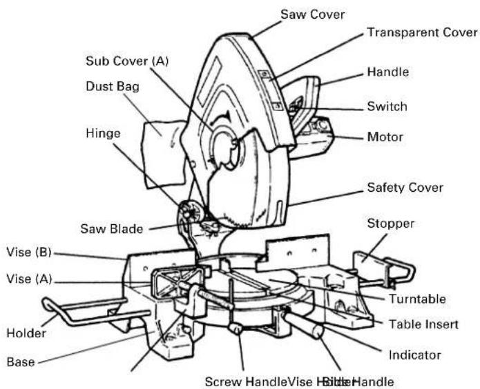
text_image
Saw Cover Transparent Cover Handle Switch Motor Sub Cover (A) Dust Bag Hinge Safety Cover Stopper Saw Blade Vise (B) Vise (A) Turntable Table Insert Indicator Holder Base Screw Handle Vise Handle HandleFig. 1
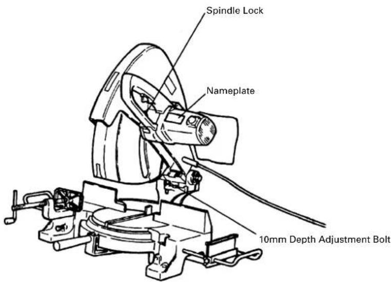
text_image
Spindle Lock Nameplate 10mm Depth Adjustment BoltFig. 2
SPECIFICATIONS
| Item Model C 15FB | ||
| Motor Type Series commutator motor | ||
| Power source Single-phase AC 60Hz | ||
| Voltage (Volts) 115 | ||
| Full-load current (Amp) 15 | ||
| Applicable Outside Dia. 15" (380 mm)saw blade Hole Dia. 1" (25.4 mm) | ||
| No load speed 3400 rpm | ||
| Max. sawing dimension | 90° | Max. Height 4 - 3/4" (122 mm) Max. Width 7 - 1/4" (185 mm)* Height 1 - 3/4" (45 mm)Width 9 - 7/16" (240 mm) |
| 45° | Max. Height 4 - 3/4" (122 mm) Max. Width 5 - 7/16" (139 mm)* Height 5 - 7/8" (150 mm)Width 1 - 3/4" (45 mm) | |
| Miter sawing range | Right and left 0° – 57° | |
| Max. opening of vise 7 - 1/4" (185 mm) | ||
| Net weight | 55 lbs. (25 kg) | |
| Cord | 2 conductor type cable 8 ft. (2.5 m) | |
For how to cut materials marked “*”, refer to page 15: 4. Cutting wide workpiece.
APPLICATIONS
Wood and aluminum sash.
Make the following preparations before operating the power tool:
1. Installation
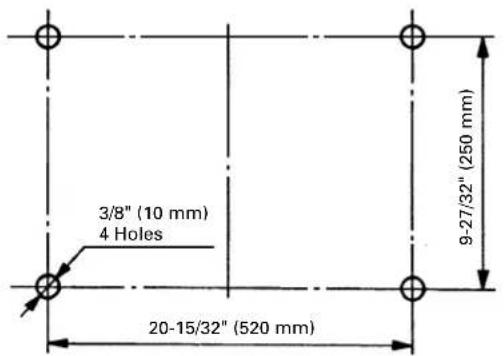
text_image
3/8" (10 mm) 4 Holes 20-15/32" (520 mm) 9-27/32" (250 mm)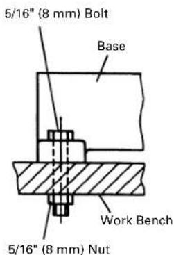
text_image
5/16" (8 mm) Bolt Base Work Bench 5/16" (8 mm) NutFig. 4
Attach the power tool to a level, horizontal work bench in accordance with Fig. 4. Select 5/16" (8 mm) diameter bolts suitable in length for the thickness of the work bench. Bolt length should be at least 2" (50 mm) plus the thickness of the work bench. For example, use 5/16" (8 mm) × 3" (75 mm) for a 1" (25 mm) thick work bench.
2. Releasing the locking pin
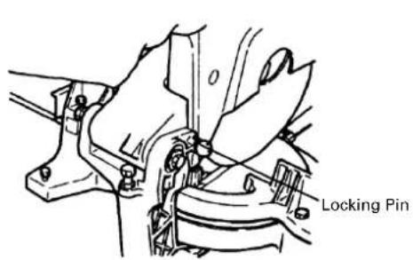
text_image
0 Locking Pin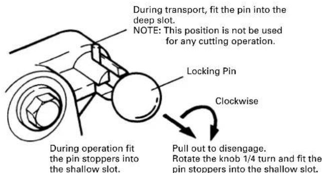
text_image
During transport, fit the pin into the deep slot. NOTE: This position is not be used for any cutting operation. Locking Pin Clockwise Pull out to disengage. During operation fit the pin stoppers into the shallow slot. Rotate the knob 1/4 turn and fit the pin stoppers into the shallow slot.Fig. 5-a Fig. 5-b
When the power tool is prepared for shipping, its main parts are secured by a locking pin. Move the handle (see Fig. 1) slightly so that the locking pin can be disengaged and adjusted as indicated in Fig. 5-b.
NOTE: Lowering the handle (see Fig. 1) slightly will enable you to disengage the locking pin more easily and safely. The lock position of the locking pin is for carrying and storage only.
3. Installing the dust bag, holder, stopper and vises.
(The dust bag, holder, stopper and vise assembly are standard accessories). Attach the dust bag, holder, stopper and vise assembly, as indicated in Fig. 1.
BEFORE USING
- Make sure the power source is appropriate for the tool.
⚠ WARNING: Never connect the power tool unless the available AC power source is of the same voltage as that specified on the nameplate of the tool. Never connect this power tool to a DC power source.
- Make sure the trigger switch is turned OFF.
⚠ WARNING: If the power cord is connected to the power source with the trigger switch turned ON the power tool will start suddenly and can cause a serious accident.
- Check the saw blade for visible defects.
Confirm that the saw blade is free of cracks or other visible damage.
- Confirm that the saw blade is attached securely to the power tool.
Using the supplied 17 mm box wrench, tighten the bolt on the saw blade spindle to secure the saw blade.
For details, see Fig. 24-a and Fig. 24-b in the section on "SAW BLADE MOUNTING AND DISMOUNTING".
- Check the safety cover for proper operation.
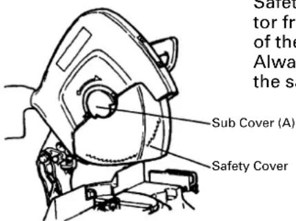
text_image
Sub Cover (A) Safety CoverFig. 6
Safety cover and sub cover (A) are designed to protect the operator from coming into contact with the saw blade during operation of the tool.
Always check that the safety cover moves smoothly and covers the saw blade properly.
⚠ WARNING: NEVER OPERATE THE POWER TOOL if the safety cover does not function smoothly.
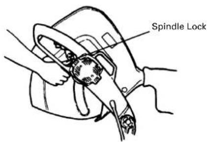
- Confirm the position of the spindle lock before using the tool.
After installing the saw blade, confirm that the spindle lock has been returned to the retract position before using the power tool (see Fig. 2).
- Check the lower limit position of the Saw Blade.
Although it was adjusted before shipment, carefully check the height of the saw blade. Confirm that the saw blade can be lowered 1-1/4" to 1-5/16" (32 mm to 33 mm) below the table insert. For details, see the section on "Checking the saw blade lower limit position".
- Check the Power Receptacle.
To prevent overheating, accidental stopping or intermittent operation, confirm that the power cord plug fits properly in the electrical receptacle and does not fall out after it is inserted. Repair or replace the receptacle if it is faulty.
- Confirm the tool's power cord is not damaged.
Repair or replace the power cord if an inspection indicates that it is damaged.
AFTER CONNECTING THE POWER PLUG TO AN APPROPRIATE AC POWER SOURCE, CHECK THE OPERATION OF THE TOOL AS FOLLOWS:
- Trial Run
After confirming that no one is standing behind, the power tool start and confirm that no operating abnormalities exist before attempting a cutting operation.
- Inspect the rotating stability of the saw blade.
For precise cutting, rotate the saw blade and check for deflection to confirm that the blade is not noticeably unstable; otherwise vibrations might occur and cause an accident.
BEFORE CUTTING
1. Cutting a groove on the table insert
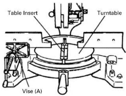
text_image
Table Insert Turntable Vise (A)Fig. 7
A groove has to be cut in the table insert, before starting operation. Secure a piece of wood about 5" (125 mm) wide to the turntable with the vise (A), to prevent the breakage of the table insert. After the switch has been turned on and the saw blade has reached its maximum speed, slowly lower the handle to cut the piece of wood, and then a groove on the table insert.
⚠️ CAUTION: Do not cut the groove too quickly; otherwise the guard might become damaged.
2. Checking the saw blade lower limit position
text_image
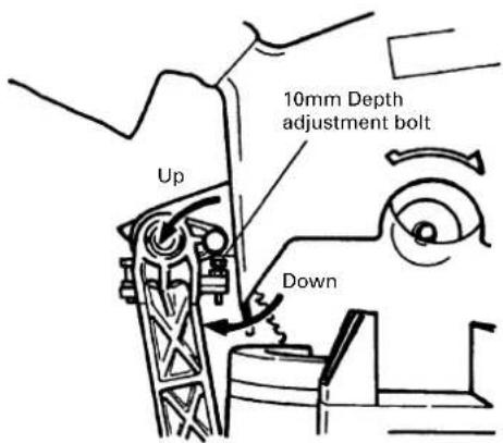
10mm Depth adjustment bolt Up DownFig. 8
Check that the saw can be lowered 1 - 1/4" to 1 - 5/16" (32 mm to 33 mm) below the table insert. If necessary, adjust as follows:
(1) Loosen the 10mm lock nut on the 10mm depth adjustment bolt.
(2) Turn the 10mm depth adjustment bolt as necessary to set the lower limit position. The saw blade goes up when the 10mm depth adjustment bolt is turned counterclockwise and down when it is turned clockwise.
(3) Once the adjustment is complete, fully tighten the 10mm lock nut.
NOTE: Before tightening the 10mm lock nut, confirm that the saw blade is adjusted so that it will not cut into the turntable. Allow a space of 3/16" (4 - 5 mm) between the saw blade and the turntable.
3. Securing the workpiece
WARNING: Always clamp or vise to secure the workpiece to the fence; otherwise the workpiece might be thrust from the table and cause bodily harm.
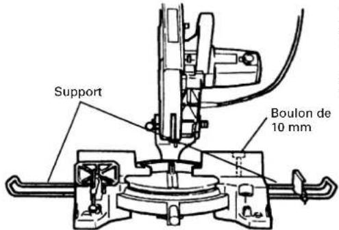
4. Installing the holders (Standard accessory)
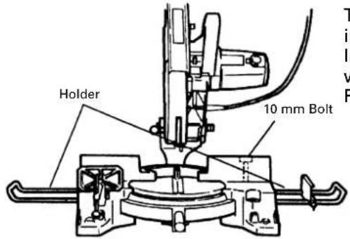
text_image
Holder 10 mm BoltFig. 9
The holders help keep longer workpieces stable and in place during the cutting operation. Install them on the right and left sides of the base and fix them with 10 mm bolts. For moving the holders, loosen the 10 mm bolts.
5. Stopper for precision cutting (Standard accessory)
The stopper facilitates continuous precision cutting in lengths of 11 - 5/8" to 18 - 1/2" (295 mm to 470 mm).
To install the stopper, attach it to the holder with the 6 mm wing bolt as shown in Fig. 10.
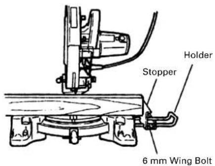
text_image
Holder Stopper 6 mm Wing BoltFig. 10
6. Handle position adjustment
text_image
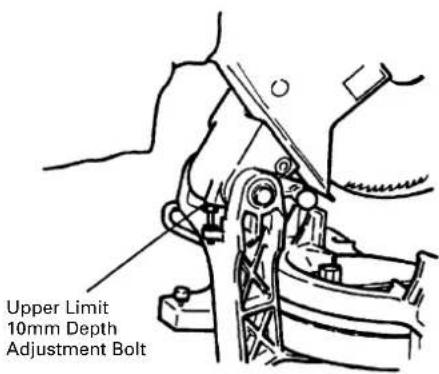
Upper Limit 10mm Depth Adjustment BoltFig. 11
During cutting operation, adjusting the upper limit 10mm depth adjustment bolt according to workpiece height as illustrated in Fig. 11, reduces the up - down handle movement range for a higher operating efficiency.
Loosen the 10 mm lock nut which fixes the upper limit 10mm depth adjustment bolt and move the handle up and down to allow the 10mm depth adjustment bolt to be set in a position suitable for the height of the workpiece to be cut. Then tighten the 10 mm lock nut.
7. Using an ink line
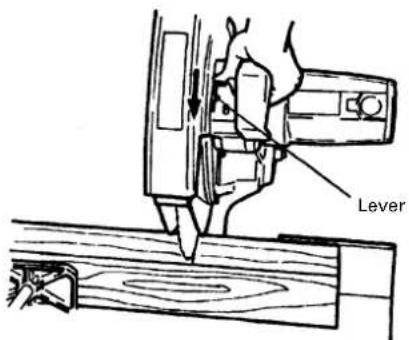
text_image
LeverFig. 12
For cutting along a pre - marked line on the workpiece, lift the safety cover by operating the lever as shown in Fig. 12, and align the saw blade with the pre - marked line, before starting cutting operation.
⚠ WARNING: Never operate the lever while the saw blade is rotating.
PRACTICAL APPLICATIONS
⚠ WARNING: * To avoid personal injury, never remove or place a workpiece on the table while the tool is being operated.
* Never place your limbs inside of the line next to warning sign while the tool is being operated. This may cause hazardous conditions (see Fig. 13).
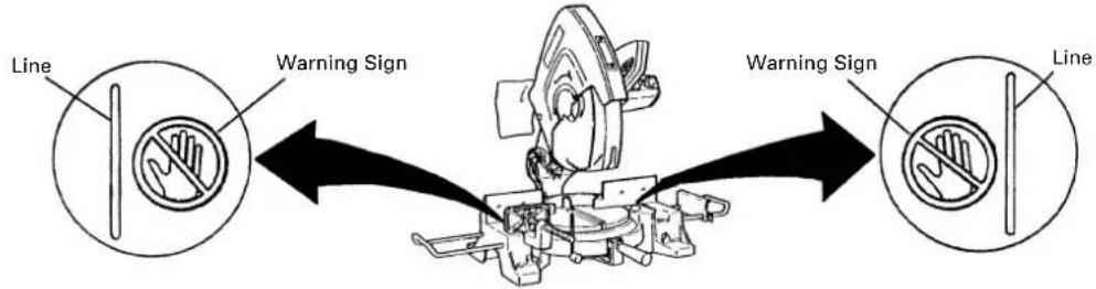
text_image
Line Warning Sign Warning Sign LineFig. 13
1. Switch operation
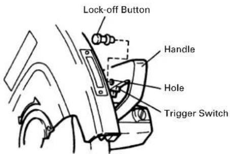
text_image
Lock-off Button Handle Hole Trigger SwitchFig. 14
The trigger switch lock-off button is designed to prevent inadvertent operation of the power tool. To operate the power tool, it is necessary to first fully insert the lock-off button into the hole on the handle as shown in Fig. 14.
The trigger switch will not operate unless the lock-off button has been pushed in.
When the trigger switch is released, the power goes off and the lock-off button automatically returns to its initial position, locking the trigger switch.
WARNING: Always remove the lock-off button from the handle when the power tool is not in use. This will ensure that the power tool cannot be turned on accidentally or by someone (especially a child) who is not qualified to use the power tool. If the lock-off button is left in the handle, serious personal injury can result. Since the lock-off button fits rather tightly, it may be necessary to turn it to the left and right during mounting and removing.
2. Cutting Operation
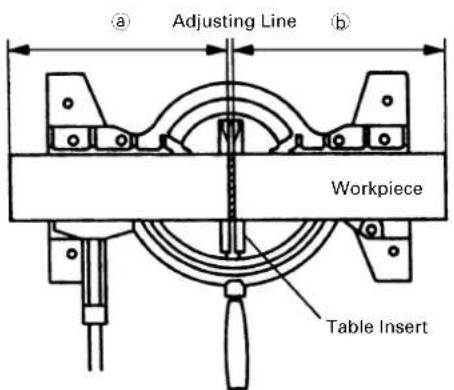
text_image
Adjusting Line Workpiece Table InsertFig. 15
(1) As shown in Fig. 15 the width of the saw blade is the width of the cut. Therefore, slide the workpiece to the right (viewed from the operator's position) when length ① is desired, or to the left when length ② is desired.
(2) Once the saw blade reaches maximum speed, push the handle down carefully until the saw blade approaches the workpiece.
(3) Once the saw blade contacts the workpiece, push the handle down gradually to cut into the workpiece.
(4) After cutting the workpiece to the desired depth, turn the power tool OFF and let the saw blade stop completely before raising the handle from the workpiece to return it to the full retract position.
⚠️ CAUTION: * Increased pressure on the handle will not increase the cutting speed. On the contrary, too much pressure may result in overload of the motor and/or decreased cutting efficiency.
⚠ WARNING: * Confirm that the trigger switch is turned OFF and the power plug has been removed from the receptacle whenever the tool is not in use.
* Always remove the lock-off button from the handle and store it in a secure place after completing the work.
3. Miter cutting procedures
text_image
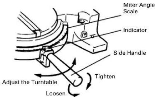
Miter Angle Scale Indicator Side Handle Tighten Adjust the Turntable LoosenFig. 16
(1) Loosen the side handle and adjust the turntable until the indicator aligns with the desired setting on the miter angle scale (Fig. 16).
(2) Re-tighten the side handle to secure the turntable in the desired position.
(3) To align the saw blade with the pre - marked line on the workpiece, watch through the saw cover window (refer to Fig. 1) to ensure alignment, before starting operation.
(4) If any cuttings, etc., collecting on the transparent cover of the saw cover window make it difficult to see the saw blade end, remove the fixing screws and clean the cover with a soft cloth.
NOTE: * Positive stops are provided at the right and left of the 0° center setting and 45° settings. Check that the miter angle scale and the tip of the indicator are properly aligned.
* Operation of the saw with the miter angle scale and indicator out of alignment, or with the side handle not properly tightened, will result in poor cutting precision.
text_image
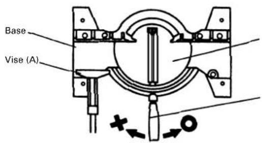
Base Vise (A)Fig. 17
text_image
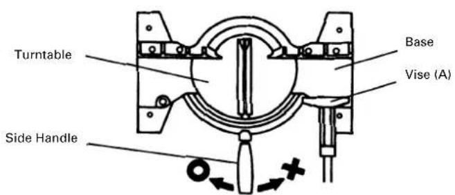
Turntable Side Handle Base Vise (A)Fig. 18
CAUTION:
When vise (A) has been mounted on the left of the base as illustrated in Fig. 17, rotate the turntable to the right to start operation. When vise (A) has been mounted on the right of the base as illustrated in Fig. 18, rotate the turntable to the left to start operation.
Be very careful not to rotate the turntable in the same direction as the vise (A) is mounted, which would cause the vise (A) to be cut by the saw blade, resulting in breakage of both.
4. Cutting wide workpiece
text_image
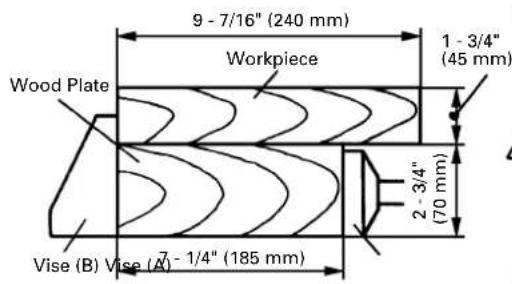
9 - 7/16" (240 mm) Workpiece 1 - 3/4" (45 mm) Wood Plate 2 - 3/4" (70 mm) Vise (B) Vise (A) - 1/4" (185 mm)Fig. 19
text_image
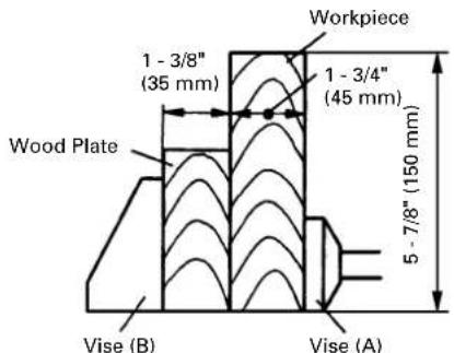
Workpiece 1 - 3/8" (35 mm) 1 - 3/4" (45 mm) Wood Plate 5 - 7/8" (150 mm) Vise (B) Vise (A)Fig. 20
(1) Fig. 19 shows the dimensions of a wide workpiece to be cut at a right angle (0°). The use of a plate as illustrated in the figure, permits cutting of wide workpieces of up to 9 - 7/16" (240 mm) (width) × 1 - 3/4" (45 mm) (height).
CAUTION:
Since the workpiece needs to be held in position by hand during cutting operation, be sure to put it into a stable, horizontal position and fix it securely before starting operation.
(2) Fig. 20 shows the dimensions of a wide workpiece to be cut at an angle of 45^ .
The use of a plate as illustrated in the figure, permits cutting of wide workpieces of up to 1 - 3/4" (45 mm) (width) × 5 - 7/8" (150 mm) (height).
Before the tool is shipped, the saw blade is set in the 5 - 1/8" (130 mm) position. Adjust the handle position to cut the wide workpiece of 5 - 7/8" (150 mm) in height.
(Refer to P. 13; "6. Handle position adjustment".)
5. Cutting easily - deformed materials, such as aluminum sash
text_image
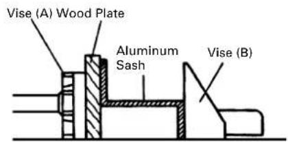
Vise (A) Wood Plate Aluminum Sash Vise (B)Fig. 21
Materials such as aluminum sash can easily deform when tightened too much in a vise assembly. This will cause inefficient cutting and possible overload of the motor. When cutting such materials, use a wood plate to protect the workpiece as shown in Fig. 21.
When cutting the aluminum materials, coat the saw blade with cutting oil (non - combustible) to achieve smooth cutting and a fine finish.
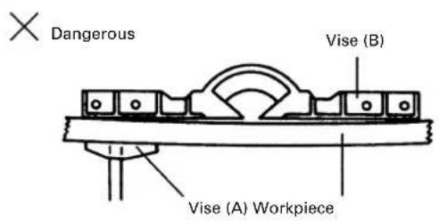
6. Cutting bent or uneven materials
To cut an uneven workpiece such as the one shown in Fig. 22, use a wood plate between vise (B) and the workpiece as shown in Fig. 23.
text_image
Dangerous Vise (B) Vise (A) WorkpieceFig. 22 Fig. 23
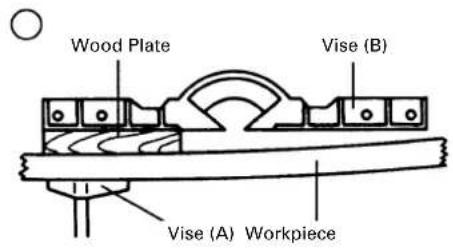
text_image
Wood Plate Vise (B) Vise (A) WorkpieceSAW BLADE MOUNTING AND DISMOUNTING
⚠ WARNING: To prevent an accident or personal injury, always turn off the trigger switch and disconnect the power plug from the receptacle before removing or installing a saw blade.
1. Mounting the saw blade (Fig. 24-a, Fig. 24-b and Fig. 25)
(1) Press in spindle lock and loosen bolt (A) with 17 mm box wrench. Since the bolt (A) is left-hand threaded, loosen by turning it to the right as shown in Fig. 24-b.
NOTE: If the spindle lock cannot be easily pressed in to lock the saw blade spindle, turn the bolt (A) with 17 mm box wrench while applying pressure on the spindle lock. The saw blade spindle is locked when the spindle lock is pressed inward.
(2) Remove the bolt (A) and washer (B)
text_image
Spindle LockFig. 24-a Fig. 24-b
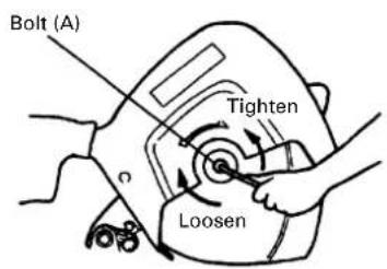
text_image
Bolt (A) Tighten Loosen(3) Lift the safety cover and mount the saw blade.
⚠ WARNING: When mounting the saw blade, confirm that the rotation indicator mark on the saw blade and the rotation direction of the saw cover (see Fig. 1) are properly matched.
text_image
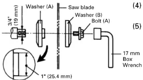
3/4" (19 mm) Washer (A) Saw blade Washer (B) Bolt (A) 17 mm Box Wrench 1" (25.4 mm) (4) (5)Fig. 25
(4) Thoroughly clean washer (B) and the bolt (A), and install them onto the saw blade spindle.
(5) Press in the spindle lock and tighten the bolt (A) by turning it to the left by 17 mm box wrench as indicated in Fig. 24-b.
⚠️ CAUTION: * Confirm that the spindle lock has returned to the retract position after installing or removing the saw blade.
* Tighten the bolt (A) so it does not come loose during operation. Confirm the bolt (A) has been properly tightened before the power tool is started.
- Dismounting the saw blade
Dismount the saw blade by reversing the mounting procedures described in paragraph 1 above. The saw blade can easily be removed after lifting the safety cover.
⚠️ CAUTION: Never attempt to install saw blades larger than 15" (380 mm) in diameter. Always install saw blades that are 15" (380 mm) in diameter or less.
MAINTENANCE AND INSPECTION
⚠ WARNING: To avoid an accident or personal injury, always confirm that the trigger switch is turned OFF and the power plug has been disconnected from the receptacle before performing any maintenance or inspection of this tool.
- Inspecting the saw blade
Always replace the saw blade immediately upon the first sign of deterioration or damage. A damaged saw blade can cause personal injury and a worn saw blade can cause ineffective operation and possible overload to the motor.
⚠️ CAUTION: Never use a dull saw blade. When a saw blade is dull, its resistance to the hand pressure applied by the tool handle tends to increase, making it unsafe to operate the power tool.
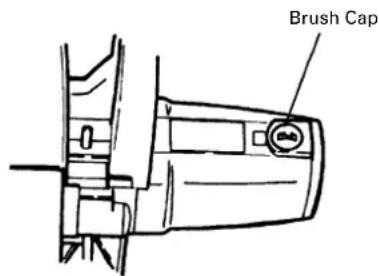
- Inspecting the carbon brushes (Fig. 26, 27)
The carbon brushes in the motor are expendable parts.
If the carbon brushes become excessively worn, motor trouble might occur.
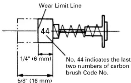
Therefore, inspect the carbon brushes periodically and replace them when they have become worn to the wear limit line as shown in Fig. 26.
Also, keep the carbon brushes clean so that they will slide smoothly within the brush holders.
The carbon brushes can easily be removed after removal of the brush caps (see Fig. 27) with a slotted (minus) screwdriver.
text_image
Wear Limit Line 44 1/4" (6 mm) 5/8" (16 mm) No. 44 indicates the last two numbers of carbon brush Code No.Fig. 26 Fig. 27
text_image
Brush Cap- Inspecting the mounting screws
Regularly inspect each component of the power tool for looseness.
Re-tighten mounting screws on any loose part.
⚠ WARNING: To prevent personal injury, never operate the power tool if any components are loose.
4. Inspecting the safety cover for proper operation
Before each use of the tool, test the safety cover (see Fig. 6) to assure that it is in good condition and that it moves smoothly.
Never use the tool unless the safety cover operates properly and it is in good mechanical condition.
5. Storage
After operation of the tool has been completed, check that the following has been performed:
(1) Trigger switch is in OFF position,
(2) Power plug has been removed from the receptacle,
(3) Lock-off button has been removed and stored in a secure place.
When the tool is not in use, keep it stored in a dry place out of the reach of children.
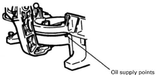
6. Lubrication
Lubricate the following sliding surfaces once a month to keep the power tool in good operating condition for a long time (see Fig. 1 and Fig. 2). Use of machine oil is recommended.
Oil supply points:
*Rotary portion of hinge
*Rotary portion of vise assembly
*Rotary portion of turntable and base (See Fig. 28)
text_image
Oil supply pointsFig. 28
7. Cleaning
Periodically remove chips, dust and other waste material from the surface of the power tool, especially from the inside of the safety cover with a damp, soapy cloth. To avoid a malfunction of the motor, protect it from contact with oil or water.
SERVICE AND REPAIRS
All quality power tools will eventually require servicing or replacement of parts because of wear from normal use. To assure that only authorized replacement parts will be used and that the double insulation system will be protected, all service (other than routine maintenance) must be performed by an AUTHORIZED HITACHI POWER TOOL REPAIR CENTER ONLY.
NOTE: Specifications are subject to change without any obligation on the part of HITACHI.
INFORMATIONS IMPORTANTES
CHOSES A NE PAS FAIRE
POUR GARANTIR UNE UTILISATION EN TOUTE SECURITE, NE JAMAIS VIOLER LES CONSIGNES SUIVANTES:
4. Installation des supports (Accessoire standard)
text_image
Support Boulon de 10 mmFig. 9
APPLICATIONS PRATIQUES
⚠ AVERTISSEMENT:
Sinagawa Intercity Tower A,
15-1, Konan 2-chome, Minato-ku, Tokyo 108-6020, Japan
Distributed by
Hitachi Koki U.S.A., Ltd.
3950 Steve Reynolds Blvd.
Norcross, GA 30093
Hitachi Koki Canada Co.
6395 Kestrel Road
Mississauga ON L5T 1Z5