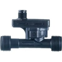
SV4051 - Flow Meter IFM - Free user manual and instructions
Find the device manual for free SV4051 IFM in PDF.


User questions about SV4051 IFM
0 question about this device. Answer the ones you know or ask your own.
Ask a new question about this device
Download the instructions for your Flow Meter in PDF format for free! Find your manual SV4051 - IFM and take your electronic device back in hand. On this page are published all the documents necessary for the use of your device. SV4051 by IFM.
USER MANUAL SV4051 IFM
Operating instructions
Vortex flow meter
SV3x51
SV4x51
SV5x51
SV6x51
SV7x51
SV8x51
Contents
1 Preliminary note 3
1.1 Symbols used 3
1.2 Warnings.... 3
2 Safety instructions.... 4
3 Intended use.... 5
3.1 Application area 5
4 Installation.... 6
4.1 Interference.... 7
5 Electrical connection.... 9
6 Maintenance, repair and disposal 10
1 Preliminary note
You will find instructions, technical data, approvals and further information using the QR code on the unit / packaging or at documentation.ifm.com.
1.1 Symbols used
√ Requirement
Instructions
Reaction, result
[...] Designation of keys, buttons or indications
→ Cross-reference

Important note
Non-compliance may result in malfunction or interference.

Information
Supplementary note
1.2 Warnings
Warnings indicate the possibility of personal injury and damage to property. This enables safe product handling. Warnings are graded as follows:

WARNING
Warning of serious personal injury
▷ If the warning is not observed, fatal and serious injuries are possible.

CAUTION
Warning of minor to moderate personal injury
▷ If the warning is not observed, minor to moderate injuries are possible.
ATTENTION
Warning of damage to property
▷ If the warning is not observed, damage to property is possible.
2 Safety instructions
- The unit described is a subcomponent for integration into a system.
- The system architect is responsible for the safety of the system.
-
The system architect undertakes to perform a risk assessment and to create documentation in accordance with legal and normative requirements to be provided to the operator and user of the system. This documentation must contain all necessary information and safety instructions for the operator, the user and, if applicable, for any service personnel authorised by the architect of the system.
-
Read this document before setting up the product and keep it during the entire service life.
- The product must be suitable for the corresponding applications and environmental conditions without any restrictions.
- Only use the product for its intended purpose (→ Intended use).
- Only use the product for permissible media.
- If the operating instructions or the technical data are not adhered to, personal injury and/or damage to property may occur.
- The manufacturer assumes no liability or warranty for any consequences caused by tampering with the product or incorrect use by the operator.
- Installation, electrical connection, set-up, operation and maintenance of the product must be carried out by qualified personnel authorised by the machine operator.
- Protect units and cables against damage.
3 Intended use
The device monitors the flow in liquid media according to the vortex measuring principle.
The device detects the flow velocity and the volume flow (volumetric flow quantity/time).
Devices with 4-wire connection also detect the temperature as a Pt1000 resistance value ( → Electrical connection ☐ 9).
The device provides an analogue signal proportional to the process value.

Pressure Equipment Directive (PED):
The units comply with the Pressure Equipment Directive and are designed and manufactured for group 2 fluids in accordance with the sound engineering practice. Use of media from group 1 fluids on request.
3.1 Application area
Liquids with the following properties:
- Water
• Hydrous media (deionised water, cooling water)

Adding an additive that influences the viscosity of the medium leads to an increase in measurement inaccuracy.
→ Compare curves and diagrams in the data sheet at documentation.ifm.com.
4 Installation

CAUTION
If the medium temperature is above 50\ °C ( 122\ °F ), parts of the housing can increase in temperature to over 65\ °C ( 149\ °F ).
▷ Risk of burns.
▶ Protect the housing against contact with flammable substances and unintentional contact.
▶ Make sure that no pressure is applied to the system.
▶ Ensure that no media can leak at the mounting location during installation.
▶ Fit the device in the pipe in accordance with the flow direction (arrow on the device).
▶ Mount the device in a way that no mechanical forces are exerted on the pipe. To do so, use angle brackets if required.
| Nominal width of the device | Maximum tightening torque |
| DN6, DN8, DN10, DN12, DN20 | 12 Nm |
| DN25 | 15 Nm |
Tab. 1: Maximum tightening torque depending on the device type

Information about available accessories at www.ifm.com
Recommended installation position:
▶ Install in front of or in a rising pipe.
▶ Avoid deposits, accumulated gas and air in the pipe system.
▶ Install the unit so that the measuring pipe is always completely filled.
▶ Make sure that pipe and sensor have the same internal diameter.
Non-recommended installation position:
• Directly in front of a falling pipe.
- In a falling pipe.
• Directly in front of the spout of a pipe.
• Directly in front of a valve.
• On the suction side of a pump.
- At the highest point of the pipe system.

Fig. 1: Recommended and non-recommended installation positions
4.1 Interference
Structures in the pipe, bends, valves, reducing pieces and the like affect the function of the unit.
▶ Adhere to the distances between sensor and interference.

Fig. 2: Minimum distances for inlet and outlet sections when changing the pipe diameter

Fig. 3: Minimum distances to 2x90° bends and to pumps

Fig. 4: Minimum distances to bends
1: Minimum distance to non-ideal bends
2: Minimum distance to ideal 90° bends with at least R 1.8 x DN
5 Electrical connection

The unit must be connected by a qualified electrician.
▶ Observe the national and international regulations for the installation of electrical equipment.
▶ Disconnect power.
▶ Connect the unit as follows:

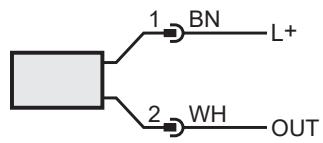
Fig. 5: 2-wire devices (SV3xxx); colours to DIN EN 60947-5-2: BN: brown; WH: white
OUT: Analogue signal for flow


Fig. 6: 4-wire devices; colours to DIN EN 60947-5-2: BN: brown; WH: white: BK: black; BU: blue
OUT: Analogue signal for flow
T1/T2: Pt1000
6 Maintenance, repair and disposal
The operation of the unit is maintenance-free.
Only the manufacturer is allowed to repair the unit.
▶ After use dispose of the device in an environmentally friendly way in accordance with the applicable national regulations.
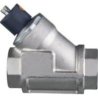
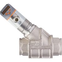
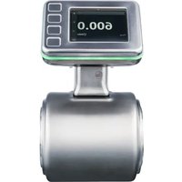
Brand : IFM
Model : SV4051
Category : Flow Meter