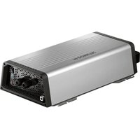
SMP 301-07 - Battery charger DOMETIC - Free user manual and instructions
Find the device manual for free SMP 301-07 DOMETIC in PDF.


User questions about SMP 301-07 DOMETIC
0 question about this device. Answer the ones you know or ask your own.
Ask a new question about this device
Download the instructions for your Battery charger in PDF format for free! Find your manual SMP 301-07 - DOMETIC and take your electronic device back in hand. On this page are published all the documents necessary for the use of your device. SMP 301-07 by DOMETIC.
USER MANUAL SMP 301-07 DOMETIC
natural_image
Exterior view of a black and silver industrial air conditioner unit (no visible text or symbols)EN Switch-mode power supply
Installation and Operating Manual.....9
Schaltnetzteil
natural_image
Line drawing of a USB connector with two connectors, one labeled '1' (no text or symbols beyond label)Please read this instruction manual carefully before installation and first use, and store it in a safe place. If you pass on the product to another person, hand over this instruction manual along with it.
Table of contents
1 Explanation of symbols....9
2 Safety instructions....10
3 Scope of delivery ....13
4 Accessories....13
5 Intended use ....13
6 Technical description .....13
7 Installing the switching power supply ....18
8 Using the switching power supply....21
9 Maintaining and cleaning the switching power supply 22
10 Troubleshooting 23
11 Warranty 23
12 Disposal.... 24
13 Technical data 24
1 Explanation of symbols

DANGER!
Safety instruction: Indicates a hazardous situation that, if not avoided, will result in death or serious injury.

WARNING!
Safety instruction: Indicates a hazardous situation that, if not avoided, could result in death or serious injury.

CAUTION!
Safety instruction: Indicates a hazardous situation that, if not avoided, could result in minor or moderate injury.

NOTICE!
Indicates a situation that, if not avoided, can result in property damage.

NOTE
Supplementary information for operating the product.
2 Safety instructions
The manufacturer accepts no liability for damage in the following cases:
- Faulty assembly or connection
- Damage to the product resulting from mechanical influences and incorrect connection voltage
• Alterations to the product without express permission from the manufacturer - Use for purposes other than those described in the operating manual
2.1 General safety

WARNING!
- This product can be used by children aged eight years or over, as well as by persons with diminished physical, sensory or mental capacities or a lack of experience and knowledge, provided they are supervised, or have been taught how to use the device safely and are aware of the resulting risks.
- Cleaning and user maintenance may not be carried out by unsupervised children.
- Only use the product as intended.
- Do not use the product in wet or damp environments or in areas where there is a risk of gas or dust explosions.
- Maintenance and repair work may only be carried out by qualified personnel who are familiar with the risks involved and the relevant regulations.
2.2 Safety when installing the product

WARNING!
- The electrical installation may only be connected by qualified personnel and only in accordance with the national regulations. Incorrect connection may cause severe hazards.
• Take the precautions necessary to ensure that children cannot interfere with the product.
Dangerous situations may occur which cannot be recognized by children!

NOTICE!
- Do not expose the product to any heat source (such as direct sunlight or heating). Avoid additional heating of the device in this way.
Electrical cables

CAUTION!
- Lay the cables so that they cannot be tripped over or damaged.
- Have damaged power cables replaced by a specialist in accordance with national regulations.

NOTICE!
- If cables have to be fed through metal walls or other walls with sharp edges, use ducts or bushings to prevent damage.
- Do not lay cables that are loose or sharply bent next to electrically conductive material (metal).
- Do not pull on the cables.
- Do not lay the AC cable and the DC cable in the same duct.
- Firmly secure the cables.
2.3 Operating the product safely

WARNING!
- Operate the product only if you are certain that the casing and the cables are undamaged.
• Always disconnect the power supply when working on the product.

NOTICE!
- Make sure the ventilation grills in the product are not covered.
- Ensure good ventilation.
2.4 Operating the battery charger safely (only SMP301-07)

DANGER!
- The battery may emit explosive gases during the charging process. Ensure that there are no sparks or flames in the vicinity of the battery. Ensure that the product is sufficiently ventilated.

WARNING!
- Wear safety glasses when handling the battery and especially when connecting and disconnecting the battery.
- In the event of the skin or eyes coming into contact with battery acid, rinse out the affected areas immediately with lots of water and call a doctor.
- Only charge rechargeable batteries.
- Only charge the battery if it is not frozen.
- Do not put the battery charger on the battery.
- Do not cover the battery charger.
- Only use the battery charger if the casing, connections and cable are undamaged.

NOTICE!
- A charging voltage of up to 15 V is possible during the charging process. Ensure that there are no consumer units connected to the battery during the charging process. This is to prevent the consumer units connected from being damaged.
- The battery charger switches to preservation mode following the charging process. If the battery charger does not switch out of charge mode, disconnect the battery charger from the battery. Have the battery charger checked by a specialist electrician.
- Regularly check the battery for damage and for defects when it is in use. A defective battery is detected by the battery charger during the charging process.
3 S c o p e o f d
- Switching power supply
- Battery charger (only SMP301-07)
• Installation and operating manual
4 A c c e s s o r i
Available as accessories (not included in the scope of delivery):
Description Ref. number
Overvoltage protection 9106505815
5 Intended use
The type SMP301-01/-02/-03/-04/-05/-07/-10 switching power supply is suitable for installation in habitable recreational vehicles (e.g. mobile homes, camper vans, boats etc.). The switching power supply is used as the voltage supply for the DC consumer units and can be supplied with AC or DC.
The battery charger of the SMP301-07 switching power supply is suitable for charging 6-cell lead batteries (lead-acid, gel, AGM) with a capacity of 50 Ah to 300 Ah. Do not use the battery charger for any other purpose and do not use it to charge other types of batteries.
The switching power supply is approved for permanent operation.
6 Technical description
The switching power supply converts an unstabilized input voltage to a stabilized output voltage. It provides a constant DC voltage of 12.7 V for DC consumer units.
For power supply, a battery can be connected to the switching power supply via the battery input (chapter "Connecting the switching power supply" on page 19).
The integrated priority circuit automatically switches over from battery operation to mains operation when an external power supply is available. The battery is automatically disconnected from the consumer unit.
Battery operation is activated automatically if mains operation is deactivated. The consumer units connected are supplied with energy via the battery.
Only SMP301-07
In mains operation, the battery charger supplies the battery with a constant charging voltage. The battery charger can supply a charging current of up to 20 A until a battery voltage of 12.7 V is reached. The battery charger can supply a charging current of up to 5 A at a battery voltage in excess of 12.7 V. The charging process for the battery is shorter if as many consumer units as possible are switched off. Once the battery is fully charged, the battery charger supplies it with a float charge.
The battery charger has the following safety functions:
• Overheating protection:
The charging current is reduced if the ambient temperature is too high.
- Deep discharge protection:
Battery operation is deactivated if the battery voltage drops below 10.8 V.
6.1 Connections and displays
SMP301-01
| Item in fig. 1, page 3 Element | |
| 1 Plug-in fuse F1 for output group 1 (maximum 15 A) | |
| 2 Plug-in fuse F2 for output group 2 (maximum 10 A) | |
| 3 Plug-in fuse F3 for output group 3 (maximum 7.5 A) | |
| 4 Plug-in fuse F4 for output group 4 (maximum 15 A) | |
| 5 Plug-in fuse F5 for output group 5 (maximum 15 A) | |
| 6 3x flat plug P5 6.3 mm for group 5 | |
| 7 3x flat plug P4 6.3 mm for group 4 | |
| 8 Flat plug P3 6.3 mm for group 3 | |
| 9 Flat plug P2 6.3 mm for group 2 | |
| 10 Flat plug P1 6.3 mm for group 1 | |
| 11 10x flat plug P7 6.3 mm battery terminal / common earth connection | |
| 12 2x flat plug P6 for positive terminal battery |
SMP301-02
Item in Element fig. 2, page 3
| 1 Plug-in fuse F1 for output group 1 (maximum 15 A) |
| 2 Plug-in fuse F2 for output group 2 (maximum 15 A) |
| 3 Plug-in fuse F3 for output group 3 (maximum 15 A) |
| 4 Plug-in fuse F4 for output group 4 (maximum 15 A) |
| 5 Plug-in fuse F5 for output group 5 (maximum 15 A) |
| 6 Flat plug P5 6.3 mm for group 5 |
| 7 Flat plug P4 6.3 mm for group 4 |
| 8 Flat plug P3 6.3 mm for group 3 |
| 9 Flat plug P2 6.3 mm for group 2 |
| 10 Flat plug P1 6.3 mm for group 1 |
| 11 4x flat plug P7 6.3 mm common earth connection |
SMP301-03
Item in Element fig. 3, page 4
| 1 Plug-in fuse F1 for output group 1 (maximum 10 A) |
| 2 Plug-in fuse F2 for output group 2 (maximum 10 A) |
| 3 Plug-in fuse F3 for output group 3 (maximum 5 A) |
| 4 Plug-in fuse F4 for output group 4 (maximum 5 A) |
| 5 Plug-in fuse F5 for output group 5 (maximum 10 A) |
| 6 3x flat plug P5 6.3 mm for group 5 |
| 7 3x flat plug P4 6.3 mm for group 4 |
| 8 Flat plug P3 6.3 mm for group 3 |
| 9 Flat plug P2 6.3 mm for group 2 |
| 10 Flat plug P1 6.3 mm for group 1 |
| 11 10x flat plug P7 6.3 mm battery terminal / common earth connection |
| 12 2x flat plug P6 for positive terminal battery |
SMP301-04
Item in Element fig. 4, page 4
| 1 Plug-in fuse F1 for output group 1 (maximum 15 A) |
| 2 Plug-in fuse F2 for output group 2 (maximum 10 A) |
| 3 Plug-in fuse F3 for output group 3 (maximum 7.5 A) |
| 4 Plug-in fuse F4 for output group 4 (maximum 15 A) |
| 5 Plug-in fuse F5 for output group 5 (maximum 15 A) |
| 6 3x flat plug P5 6.3 mm for group 5 |
| 7 3x flat plug P4 6.3 mm for group 4 |
| 8 Flat plug P3 6.3 mm for group 3 |
| 9 Flat plug P2 6.3 mm for group 2 |
| 10 Flat plug P1 6.3 mm for group 1 |
| 11 10x flat plug P7 6.3 mm battery terminal / common earth connection |
| 12 2x flat plug P6 for positive terminal battery |
SMP301-05
Item in Element fig. 5, page 5
| 1 Plug-in fuse F1 for output group 1 (maximum 15 A) |
| 2 Plug-in fuse F2 for output group 2 (maximum 10 A) |
| 3 Plug-in fuse F3 for output group 3 (maximum 7.5 A) |
| 4 Plug-in fuse F4 for output group 4 (maximum 15 A) |
| 5 Plug-in fuse F5 for output group 5 (maximum 15 A) |
| 6 3x flat plug P5 6.3 mm for group 5 |
| 7 3x flat plug P4 6.3 mm for group 4 |
| 8 Flat plug P3 6.3 mm for group 3 |
| 9 Flat plug P2 6.3 mm for group 2 |
| 10 Flat plug P1 6.3 mm for group 1 |
| Item in fig. 5, page 5 | Element |
| 11 | 10x flat plug P7 6.3 mm battery terminal / common earth connection |
| 12 2x flat plug P6 for positive terminal battery | |
SMP301-07
| Item in fig. 6, page 5 | Element |
| 1 AC plug | |
| 2 LED LD6B “battery charging status” | |
| 3 LED LD6 “battery fuse defective” | |
| 4 2x flat plug P6 for positive terminal battery | |
| 5 Battery fuse F6 (20 A type ATO) | |
| 6 Plug-in fuse F1 for output group 1 (maximum 15 A) | |
| 7 Plug-in fuse F2 for output group 2 (maximum 15 A) | |
| 8 Plug-in fuse F3 for output group 3 (maximum 15 A) | |
| 9 Plug-in fuse F4 for output group 4 (maximum 15 A) | |
| 10 Plug-in fuse F5 for output group 5 (maximum 15 A) | |
| 11 3x flat plug P5 6.3 mm for group 5 | |
| 12 3x flat plug P4 6.3 mm for group 4 | |
| 13 Flat plug P3 6.3 mm for group 3 | |
| 14 Flat plug P2 6.3 mm for group 2 | |
| 15 Flat plug P1 6.3 mm for group 1 | |
| 16 5x LED “plug-in fuse F1–F5 defective” (LD1–LD5) | |
| 17 | 10x flat plug P7 6.3 mm battery connection / common earth connec-tion |
The LED LD6B indicates the battery charging status as follows:
-
Main charge (12.7 V):
flashes yellow slowly (1 second on, 1 second off)
• Equalizing charge (approx. 14.4 V):
flashes yellow quickly (0.5 seconds on, 0.5 seconds off) -
Charging process complete:
lights up yellow - Fault :
flashes yellow very quickly
SMP301-10
| Item in fig. 7, page 6 | Element |
| 1 Plug-in fuse F1 for output group 1 (maximum 15 A) | |
| 2 Plug-in fuse F2 for output group 2 (maximum 10 A) | |
| 3 Plug-in fuse F3 for output group 3 (maximum 7.5 A) | |
| 4 Plug-in fuse F4 for output group 4 (maximum 15 A) | |
| 5 Plug-in fuse F5 for output group 5 (maximum 15 A) | |
| 6 3x flat plug P5 6.3 mm for group 5 | |
| 7 3x flat plug P4 6.3 mm for group 4 | |
| 8 Flat plug P3 6.3 mm for group 3 | |
| 9 Flat plug P2 6.3 mm for group 2 | |
| 10 Flat plug P1 6.3 mm for group 1 | |
| 11 | 10x flat plug P7 6.3 mm battery terminal / common earth connection |
| 12 2x flat plug P6 for positive terminal battery | |
| 13 CI bus connection | |
7 Installing the switching power supply
7.1 Fastening the switching power supply
When selecting the installation location, pay attention to the following instructions:
- The switching power supply must be installed vertically on a wall (maximum ambient temperature 50^ ) or horizontally on the ground or on a pedestal (maximum ambient temperature 40^ and maximum load 75% ).
- The optimum installation position is vertically on a wall.
- The switching power supply must be installed in a location that is protected from moisture.
- The switching power supply must not be installed in areas with easily flammable materials (e.g. gas cylinder lockers).
- The switching power supply must not be installed in a dusty environment.
- The place of installation must be well ventilated. A ventilation system must be available when the device is installed in small, enclosed spaces. Please observe the minimum clearance around the switching power supply (fig. 8, page 7).
- There must be free space in front of the ventilation grills.
- When ambient temperatures are higher than those stated above (such as in engine or heating compartments, or when exposed to direct sunlight), the heat produced by the switching power supply when under load can lead to automatic shutdown.
- The device must be installed on a level and sufficiently sturdy surface.

NOTICE!
Before drilling any holes, make sure that no electrical cables or other parts of the vehicle can be damaged by drilling, sawing and filing.
Fasten the switching power supply as follows:
▶Screw one screw through each of the four bore holes in the four fastening tabs (fig. 9 1, page 8).
7.2 Connecting the switching power supply
SMP301-02
Please note that flat plugs P1–P5 are individually fused via plug-in fuses F1–F5 in the following manner:
| Flat plug Fuse Fuse assignment | Maximum permissible current | |
| P1 F1 15 A 15 A | ||
| P2 F2 | 15 A 15 A | |
| P3 F3 | 15 A 15 A | |
| P4 F4 | 15 A 15 A | |
| P5 F5 | 15 A 15 A | |
▶ Press the two tabs (fig. 9 3, page 8) in the direction indicated by the arrows and lift the cover off (fig. 9 2, page 8).
▶ Connect the positive terminal of the consumer units to the flat plugs P1–P5 (fig. 26–10, page 3).
▶Connect the negative terminal of the consumer units to one of the flat plugs P7 (any pin) (fig. 2 11, page 3).
▶Connect the AC connection cable to the AC plug.
▶Secure all cables with strain relief clamps.
SMP301-01/-03/-04/-05/-07/-10
Please note that flat plugs P1–P6 are individually fused via plug-in fuses F1–F6 in the following manner:
| Flat plug Fuse Fuse assignment | Maximum permissible current | ||
| P1 F1 10 A | 15 A | ||
| P2 | F2 | 10 A | 15 A |
| P3 | F3 | 5 A | 15 A |
| P4 | F4 | 5 A | 15 A |
| P5 | F5 | 10 A | 15 A |
| P6 Only SMP301-07 | F6 | 20 A | 20 A |
▶ Press the two tabs (fig. 9 3, page 8) in the direction indicated by the arrows and lift the cover off (fig. 9 2, page 8).
▶ Connect the positive terminal of the consumer units to the flat plugs P1–P6 (fig. 36–10, page 4).
▶Connect the negative terminal of the consumer units to one of the flat plugs P7 (any pin) (fig. 3 11, page 4).
▶ Connect the positive terminal of the battery to one of the flat plugs P6.
- SMP301-01/-03/-04/-05/-10: z. B. fig. 1 12, page 3
- SMP301-07: fig. 6 4, page 5
▶Connect the negative terminal of the battery to one of the flat plugs P7 (any pin).
- SMP301-01/-03/-04/-05/-10: z. B. fig. 1 11, page 3
- SMP301-07: fig. 6 17, page 5
▶Connect the AC connection cable to the AC plug.
▶ Ensure that the cable length between the battery and the switching power supply is not more than 2 m.
▶Secure all cables with strain relief clamps.
8 Using the switching power supply
The switching power supply switches on as soon as an external power supply is available.
Only replace a plug-in fuse that has blown (1–5 in fig. 2, page 3 to fig. 7, page 6) with a plug-in fuse of equivalent quality.
Please contact the manufacturer's branch in your country (see the back of the instruction manual for the addresses) or your retailer if the function cannot be restored by switching on the fuses or replacing the plug-in fuse.
8.1 Replacing the plug-in fuses

NOTE
The positioning of the plug-in fuses is used to configure manufacturer-specific functions.
When replacing a plug-in fuse, take care to fit the replacement in the same place. Malfunctions may occur otherwise.
▶Disconnect all consumer units from the switching power supply.
▶ Disconnect the switching power supply from the power supply.
▶ Press the two tabs (fig. 9 3, page 8) in the direction indicated by the arrows and lift the cover off (fig. 9 2, page 8).
▶ Only replace plug-in fuses that have blown with new plug-in fuses of the type "ATO Type – LITTLEFUSE" and the same rating.
▶Re-attach the cover to the switching power supply.
▶Put the switching power supply back into operation.
If the plug-in fuse is tripped again, please contact the manufacturer's branch in your country (see the back of the instruction manual for the addresses) or your retailer.
8.2 Using the surge protector (optional)
The optional surge protector (item number 9106505815) is connected on the supply side of the switching power supply. The surge protector disconnects the power supply line if the input voltage exceeds approx. 270 V.
▶ Check whether the red LED (fig. 10 1, page 8) lights up.
√If the red LED lights up, this indicates that a voltage surge has occurred.
▶Wait 20 to 30 minutes.
The surge protector resets itself automatically as soon as the voltage returns to a permissible value. Once the voltage has reached a permissible value, the red LED remains lit up for 20 to 30 minutes.
9 Maintaining and cleaning the switching power supply

NOTICE!
Do not use any sharp or hard objects for cleaning since they may damage the device.
▶ Disconnect the switching power supply from the power supply.
▶Clean the switching power supply using a cloth as required.
10 Troubleshooting
Fault Cause Repair
| 12 V outputs not supplied when the device is operating in mains supply mode. | The plug-in fuse of the associated 12 V output is defective. The red LED next to the plug-in fuse lights up. | Replace it with a plug-in fuse of equivalent quality. |
| The switching power supply has switched off as a result of the surge protector. The red LED (fig. 101, page 8) lights up. | The surge protector resets itself automatically as soon as the voltage returns to a permissible value. Otherwise, contact customer service. | |
| 12 V outputs are not being supplied in battery operation. | The plug-in fuse of the associated 12 V output is defective. The red LED next to the plug-in fuse lights up. | Replace it with a plug-in fuse of equivalent quality. |
| The battery has been connected incorrectly. | Connect the battery correctly (chapter “Connecting the switching power supply” on page 19). |
11 Warranty
The statutory warranty period applies. If the product is defective, please contact the manufacturer's branch in your country (see the back of the instruction manual for the addresses) or your retailer.
For repair and warranty processing, please include the following documents when you send in the device:
• A copy of the receipt with purchasing date
- A reason for the claim or description of the fault
12 Disposal
▶ Place the packaging material in the appropriate recycling waste bins wherever possible.
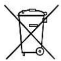
If you wish to finally dispose of the product, ask your local recycling centre or specialist dealer for details about how to do this in accordance with the applicable disposal regulations.
13 Technical data
| SMP301-01 SMP301-02 | ||
| Ref. no.: 9106504722 910 | 6504643 | |
| Design: with relay; | with external 12 V supply, outputs 1 and F5 are de-energized | without relay; no priority circuit available |
| Nominal input voltage: 230 V~12 V--- | ||
| Constant output power: 350 W | ||
| Output voltage: 12.7 V--- | ||
| Amperage: 27 A | ||
| Ambient temperature: | -10 °C to 40 °C | |
| Housing: | Protection class 20 | |
| Dimensions (L x W x H): | 240 x 207 x 56 mm | |
| Weight: | 1 kg | |
| Inspection/certification: |      SMP301-03 SMP301-04 SMP301-03 SMP301-04 | |
| Ref. no.: 9106504717 910 | 6504929 | |
| Design: with relay; | with external 12 V supply all outputs are live | with relay; with external 12 V supply, output F1 is de-energized |
| Nominal input voltage: 230 V~12 V--- | ||
| Constant output power: 350 W | ||
| Output voltage: 12.7 V--- | ||
| Amperage: 27 A | ||
| Ambient temperature: -10 °C to 40 °C | ||
| Housing: Protection class 20 | ||
| Dimensions (L x W x H): | 240 x 207 x 56 mm | |
| Weight: | 1 kg | |
| Inspection/certification: |      SMP301-05 SMP301-10 SMP301-05 SMP301-10 | |
| Ref. no.: 9106505097 910 | 6506835 | 9106506674 |
| Design: with relay; | with external 12 V supply, outputs 1 and F5 are de-energized | with relay;F1 without priority circuit only active with 230 V supply, F2-F5 with priority circuit, F4 and F5 with bypass function, F5 can also be controlled via the CI bus |
| Nominal input voltage: 230 V~12 V== | ||
| Constant output power: 350 W | ||
| Output voltage: 12.7 V== | ||
| Amperage: 27 A | ||
| Ambient temperature: -10 °C to 40 °C | ||
| Housing: Protection class 20 | ||
| Dimensions (L x W x H): | 240 x 207 x 56 mm | |
| Weight: | 1 kg | |
| Inspection/certification: |      | |
| SMP301-07 | ||
| Ref. no.: 9106505556 | ||
| Design: with battery charger | ||
| Nominal input voltage: 230 V~ | 12 V--- | |
| Constant output power: 350 W | ||
| Output voltage: 12.7 V--- | ||
| Amperage: 27 A | ||
| Ambient temperature: -10 °C to 40 °C | ||
| Housing: Protection class 20 | ||
| Dimensions (L x W x H): | 240 x 207 x 56 mm | |
| Weight: 1 kg | ||
| Inspection/certification: |      | |
6 Description technique
▶ Vent 20 – 30 minutter.
dometic.com/sales-offices