
Kompakt F810 - Electric bike TELEFUNKEN - Free user manual and instructions
Find the device manual for free Kompakt F810 TELEFUNKEN in PDF.

| Brand | Telefunken |
| Model | Kompakt F810 |
| Category | Electric bicycle (Pedelec) |
| Unladen weight | approx. 25 kg |
| Maximum total permissible weight | 150 kg (except folding bike: 120 kg) |
| Rated motor power | 250 W |
| Rated battery voltage | 36 V DC |
| Battery type | Removable lithium-ion (frame, luggage rack or seat tube depending on version) |
| Charging time | approx. 5 to 6.5 h |
| Range | 20 to 100 km depending on use, assistance and conditions |
| Maximum assisted speed | 25 km/h |
| Assistance levels | 5 levels (1 to 5) + walk mode |
| Transmission type | Derailleur or integrated gear hub depending on version |
| Brakes | Hand brakes (V-brake, cantilever, disc or coaster brake depending on version) |
| Lighting | Front headlight and rear light (wired or self-powered depending on version) |
| Tires | 28 x 1.75 (47-622) or equivalent |
| Frame | Aluminum or steel depending on version (high-quality paint) |
| Suspension | Rigid or suspended fork depending on version |
| Included accessories | Charger, battery keys, Pedelec passport |
| Cleaning and maintenance | Clean with a damp cloth; no high-pressure cleaner |
| Safety | Lights, reflectors, brakes compliant with StVZO; automatic motor cut-off when braking |
| Statutory warranty | 24 months (battery: 6 months) |
| Standards | EN 15194 / EN ISO 4210-2 |
Frequently Asked Questions - Kompakt F810 TELEFUNKEN
User questions about Kompakt F810 TELEFUNKEN
0 question about this device. Answer the ones you know or ask your own.
Ask a new question about this device
Download the instructions for your Electric bike in PDF format for free! Find your manual Kompakt F810 - TELEFUNKEN and take your electronic device back in hand. On this page are published all the documents necessary for the use of your device. Kompakt F810 by TELEFUNKEN.
USER MANUAL Kompakt F810 TELEFUNKEN
Grun = Ladung beendet
Entsorgung
| 1 2 3 | 4 5 6 7 | 8 9 | |||||||
| 0-3 / 1-3 50% 74% | 92% - - | - - - - | |||||||
| 0-5 / 1-5 50% 61% | 73% 85% | 96% | - - - | ||||||
| 0-7 / 1-7 40% 50% | 60% 70% | 80% | 90% 96% - - | ||||||
| 0-9 / 1-9 25% 34% | 43% 52% | 61% | 70% 79% 88% 96% |
In the event of theft, your Pedelec-Pass can be used to describe your Pedelec to the police or insurance company. For this reason, complete it fully immediately after purchase and keep it safe. Liability for faulty goods can only be claimed by presenting the purchase receipt and the completed Pedelec-Pass.
Frame no.:
Brand: Model designation:
EAN: Key no.:
Purchase date: Purchase price:
Type:
City
Trekking Ladies
MTB Hardtail Unisex
MTB Full Suspension
Folding bike
Motor:
Front motor
Centre motor
Rear motor
Frame colour: Rim colour:
Fork colour:
Tyre size: Special equipment:
Frame type:
Men's
Owner Purchaser
Name: Name:
First name: First name:
Street: Street:
Postcode: Postcode:
Town: Town:
Phone: Phone:
E-Mail: E-Mail:
Contents
Pedelec-Pass 3
Introduction & important information. 5
Design of a Pedelec 10
Assembly information / before the first ride 12
Pedelec components 14
Pedelec components - battery 16
Pedelec components - control unit 19
Self-help tips 27
Cleaning, maintenance, storage 29
Maintenance 30
Proof of inspection 43
Dear customer,
You have decided to purchase one of our products. We would like to thank you for the trust you have placed in us and wish you much enjoyment with your new Pedelec.
To make sure that your riding enjoyment lasts as long as possible, we have compiled lots of useful information on the topic of Pedelecs/E-Bikes. If you have additional questions, or need assistance, please contact your dealer or contact us directly by phone or e-mail.
Wishing you a safe and pleasant ride!
Karcher AG
Gewerbestr. 19
75217 Birkenfeld
You can contact our service department as follows:
Phone: +49 (0)7082 9254-20
Fax: +49 (0)7082 9254-24
e-mail: service@karcher-products.de
Information on use:
Reproduction, translation and copying, including extracts is not permitted without our prior written approval.
We reserve the right to make technical changes versus the details and diagrams shown here.
The statements included are not guaranteed to be complete. Requirements may change with changes in law. For this reason, please take note of official publications; these shall have exclusive priority.
We accept no liability for misdemeanours which occur based on our statements.
Notes regarding this handbook
Please read this handbook very thoroughly and take note of the information we have provided.
These are provided to ensure your safety and a long life for your Pedelec.
This handbook contains functional descriptions and equipment versions for different models. Not all functions or components described may be fitted to your Pedelec. This does not constitute a legal claim on these components or functions.
Introduction & important information
Intended use
Only use this Pedelec on the terrain for which it has been built and approved. Never overload your bike. Riding on unsuitable terrain or with excessive load leads to increased wear and can result in component failing. Risk of crashing!
K archer AG Pedelecs are exclusively intended for private use.
If you intend to use a child seat on the luggage rack, please comply with the maximum permitted total weight on the rack (as specified on the rack) as well as the permitted total weight of the child seat manufacturer. Carefully enclose the spring rings under the saddle to prevent the child's fingers being trapped. If child trailers or tag-alongs are fitted, please ensure that these are fitted correctly according to the manufacturer's operating manual, and that the permitted total weight is taken into account.
Only use tested child seats, child trailers and tag-alongs (e.g. DIN/GS-tested) and in all cases make sure that they are assembled correctly as per the manufacturer's instructions. If in doubt, speak to your local dealer.

If the maximum permitted total weight on the rack (as specified on the rack) is less than 27 kg, then the rack is not suitable for mounting a child seat.
Special notes for Pedelecs
Pedelec applications
- Do not use the Pedelec for competitions.
- Avoid large puddles and do not ride through water. The Pedelec is not designed for this.
- As far as possible avoid riding in extreme weather conditions.
Notes on battery and charging unit
Drive unit, battery and charging unit are matched and are approved only for use with your Pedelec. Do not use the battery or the charging unit for other systems. Only use approved battery types.
Depending on the battery, the charging time is between approx. 5 - 6.5 h. Only allow the unit to charge unattended for a maximum of 1 h, after this check the charging process regularly, and if req. disconnect the charging unit or the battery from the mains.
Information on lighting
If your Pedelec is fitted with a battery-operated light, the battery must always be fitted when riding on the road. This will make sure that the lighting system is operational at all times.
Information on the total weight
The details regarding the permissible total weight of your Pedelec can be found on the rating plate. This can be found on the frame of the Pedelec. If you are in any doubt, please contact your dealer.
Information on the manipulation of the electric system
The electric system of the pedelec may not be manipulated or altered in any way. Also bear in mind the possibility that third persons could do so while the pedelec is not under your supervision.
Information on the first ride with electric assistance
Familiarise yourself with the Pedelec before the first ride. Please consider that other traffic users may incorrectly judge your speed. The Pedelec only assists you as long as you pedal, the faster you pedal the faster the Pedelec will go. When a speed of 25km / h , the assistance switches off automatically.
Likewise, during a braking operation (front or rear brake), the assistance is interrupted automatically. Make sure that the start assistance is not activated inadvertently while at standstill e.g. at traffic lights.
For this reason, always keep one brake pressed to prevent the motor cutting in inadvertently.
Based on experience, it is a good idea to leave the assistance switched off completely for the first ride, to get used to the handling. Activate the assistance and first get used to the lowest level of assistance. This can then be increased bit by bit.
When working on the Pedelec as well as when cleaning, it is always recommended to disconnect the power supply so that the system cannot be switched on inadvertently. Only clean the Pedelec with a damp cloth, do not use a pressure washer or steam cleaner. This could cause inadvertent entry of water into the electronics and result in a short-circuit. Do not use aggressive cleaning agents, which could damage the paint or plastic parts.
Key data regarding the Pedelec
Rated power:
250 Watt
Rated voltage:
36V DC
Cut-out speed:
25 km/h
Empty weight:
approx. 25kg
Maximum allowable total weight: 150kg (unless otherwise specified on the EPAC label)
120 kg (folding bike)
The technical data may differ depending on the model and the equipment. The data for your model can be found on the EPAC label, on the frame.
The Pedelec has been manufactured according to EN 15194 / EN ISO 4210-2.
The A-weighted emission sound pressure level at the driver ears is less than 70 dB(A).
Safety information
Please pay attention to the following safety information. Failure to comply with this can lead to accidents as well as damage to property and personal injury.
- First familiarise yourself with the functions and handling of your new Pedelec away from the public road. Due to its additional weight, the braking distance of the Pedelec is longer than a standard bike. In particular, practice starting, braking and riding around tight corners.
- Always follow the laws and traffic regulations of the relevant country where the Pedelec is being used. In Germany, these regulations are set out in the StVZO (Road Traffic Licensing Act) and StVO (Road Traffic Act).
- According to the StVO, every user of the public roads must ensure that their behaviour does not endanger, damage or excessively inconvenience other road users. For this reason, always ride observantly and carefully. Be considerate to other road users.
- Your Pedelec must only be ridden on public roads if it is equipped with the equipment mandated by national laws in the place of use.
According to the StVZO in Germany a Pedelec must be fitted with
- two independently-functioning brakes,
- a clearly audible bell,
- a functional front and rear light,
- spoke reflectors or side strips on the rim or tyre,
pedal reflectors, - a white forwards-facing reflector (if not integrated into the light),
-
a red rear-facing reflector (wide-area Z-reflector).
-
In poor weather conditions, such as rain, snow or ice, special care should be taken when riding, or delay riding to a later point in time. The braking performance in particular can be substantially reduced in poor weather conditions.
In darkness and poor visibility, the lights should always be switched on. Not only will you see better with the lights switched on, but you will also be seen better by other road users. - We recommend wearing a cycling helmet to reduce the risk of head injuries.
- Wear high-visibility clothing with reflective strips to be seen more easily and more quickly by other road users.
-
Your Pedelec has rotating and moving parts. Unsuitable clothing, incorrect handling or lack of attention can result in injuries.
-
legwear should be close-fitting. Use cycle clips if req.
Introduction & important information
- Items of clothing (e.g. scarves, skirts, cords, etc.) should not hang down, since these may become trapped in the spokes.
- Shoes should be non-slip and provide adequate foot support.
- The maximum permissible total weight of the Pedelec must not exceed that shown on the rating plate (located on the Pedelec frame). As well as the Pedelec, this maximum permitted weight also includes the rider as well as other loads of any kind (e.g. basket and pannier bags including contents, child set inc. child, trailer including towed load). Excessive load can result in damage and accidents with the risk of injuries.
Technical modifications must only be carried out in accordance with the StVZO and the DIN EN ISO standard shown on the rating plate. This applies for safety-relevant components in particular, such as e.g. frame, forks, handlebars, saddle, seat post, luggage rack, all brake components (especially brake levers and brake pads), lighting systems, cranks, wheels, trailer couplings, tyres and tubes.

As is the case with all mechanical components, a Pedelec is subject to wear and high loads. If the design life of a component is exceeded, the component may fail suddenly, possibly causing injury to the rider.
Any kind of cracks, scratches or colour changes on highly-stressed areas is a sign that the life of the component has been reached, and that the part should be replaced.
If you are unsure in relation to the replacement of components on your Pedelec, especially brake or wheel elements, please contact your specialist bike dealer.
Special information
According to section 1 of the Road Traffic Licensing Act, every user of the public roads must ensure that their behaviour does not endanger, damage or excessively inconvenience other road users.
Pay attention to this during every ride! The national road traffic act regulations of the country where the Pedelec is used apply.
- Based on their design and equipment - with or without suspension systems - Pedelecs with on-road equipment are intended to be used on the public roads and surfaced paths. The necessary safety equipment has been supplied by the manufacturer, and must be regularly checked by the user - and if required, repaired.
The manufacturer accepts no responsibility for all other types of use, e.g. the failure to comply with safety information in this manual as well as those of the component manufacturers. This applies in particular for:
-off-road use of the road bike,
- overloading as well
- incorrect rectification of defects.
Product liability/ statutory warranty
You are entitles to a statutory warranty of 24 months after the purchase of this Pedelec. Within this period, our dealer will honour the statutory warranty according to the service declaration by rectifying any defects found. Wear parts are not included within this service. The pre-requisite is that the Pedelec is used for its intended purpose.
No product liability exists for:
- Manipulation of the electric system
- Damage to paint or chrome-plating caused by weather, moisture or environmental factors (especially air containing ammonia or salts).
- Improper treatment / use
-
Modifications versus the as-supplied condition of the Pedelec
-
Use-related wear of for example
-motor
-tyres
- brake parts
- chains
- suspension elements
- bearing components
-cables
- bulbs
-batteries
- Grossly careless or wilful damage
- Damage from using the bike/Pedelec in competitions
- Damage following extraordinary events, e.g. an accident
Pedelec batteries have a limited warranty of 6 months.
Disposal of waste electrical and electronic devices
This symbol on the product indicates that it must not be disposed of within normal household waste. A special zero-cost disposal system exists for electrical and electronic devices. Further information is available from your local waste disposal point or from the dealer where you purchased this product. By disposing of these items separately, you are helping to protect the environment and the health of your fellow human beings.
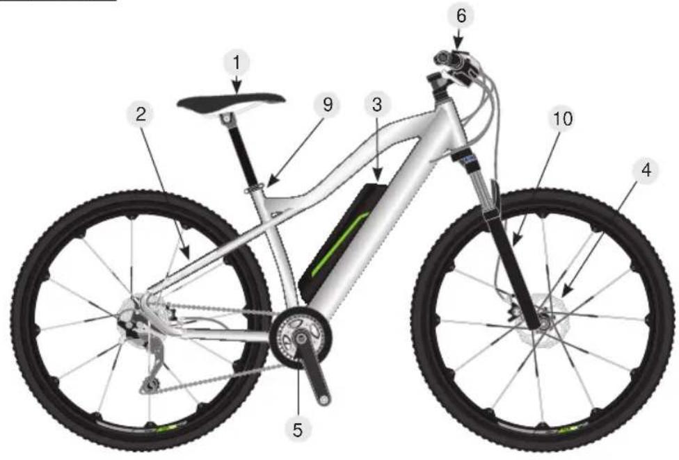
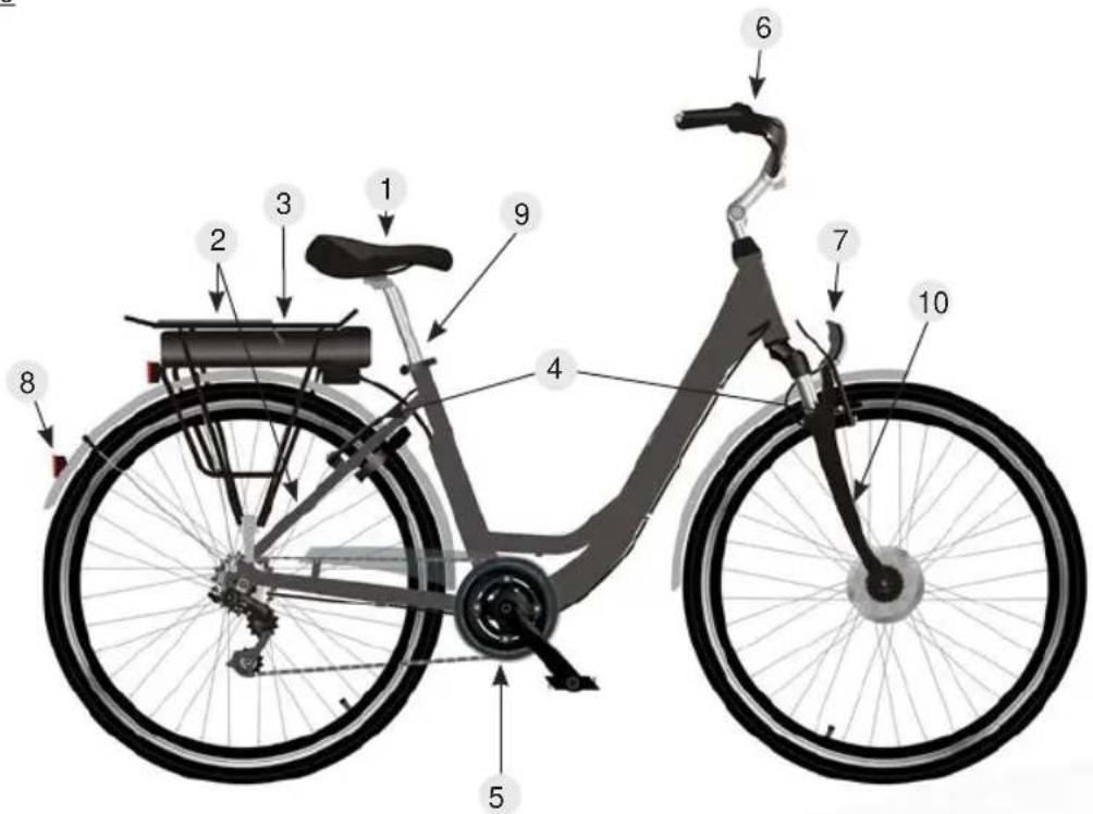
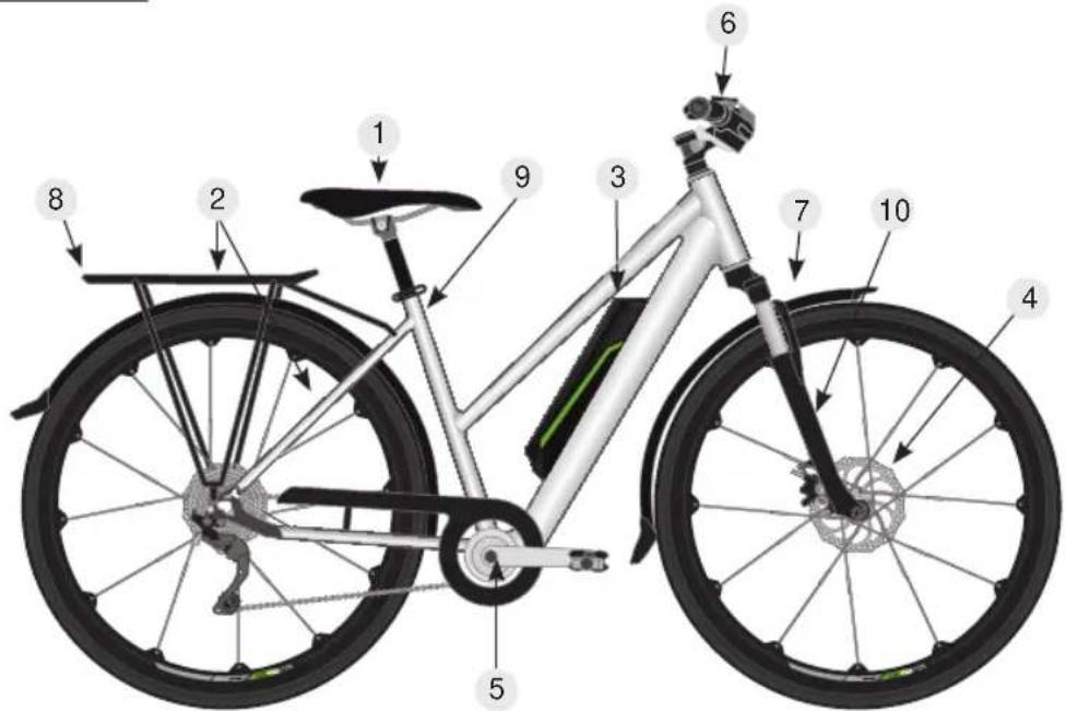
Design of a Pedelec
We would like to acquaint you more closely with the terms used in bike design, so that if you encounter technical problems, it will be easier for you to describe the fault as accurately as possible.

The following diagrams are provided as a simplified illustration. The actual components/ equipment and colour of your Pedelec may vary.
Mountain bike - Hardtail
City bike
Trekking bike - ladies
Trekking bike - men's
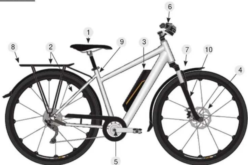
- Saddle/seat post
- Luggage rack/chainstay
- Battery and battery mount
- Brake system/disc/caliper
-
Cranks/chainwheel
-
Display/handles
- Front light (in part not shown)
- Rear light (in part not shown)
- Seat post
- Fork/suspension fork
Assembly information / before the first ride

first please make the following adjustments to your Pedelec as per your personal requirements.
If you are not confident in doing so, ask for your Pedelec to be assembled and prepared by a qualified technician.
Stem/handlebar
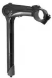
- Undo the clamping screw under the rubber cover of the stem using a 4 or 5mm hex key.
- Align the handlebar so that it is straight.
- Re-tighten the clamping screws (10 Nm).
- Check all screws on the stem to make sure that they are tight
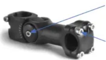
- Undo the side clamping screws of the stem using a 4 or 5mm hex key.
- Align the handlebar so that it is straight.
- Re-tighten the clamping screws (10 Nm).
- Then tighten the four screws on the clamp.
Installing pedals
When installing pedals, please make sure that you note the marking (L) left and (R) right.
The marking applies in the direction of travel. The pedals are always screwed on in a forward direction, and therefore have opposite threads. To prevent corrosion from dirt and water and the resulting grinding noises, we recommend coating the thread with assembly grease. Do not overtighten!
Tightening torque: 35 Nm
Crank tightening torque: 40 Nm - essential to re-tighten after 50 km!
Adjusting the saddle
To set the optimum seat height, you should sit on your bike with the heel of one foot positioned on the pedal in the bottom position. Your leg should now be fully extended.
To calculate the minimum saddle height, multiply your stride length by 0.885 - this provides the minimum saddle height.
The angle of the saddle can be changed by undoing the hex head screw. Please click the saddle into the desired position and re-tighten the hex head screw.

It is essential to comply with the minimum insertion depth of the seat post!
There is a marking on the seat post which shows the minimum amount of seat post which must be in the seat tube.
Failure to comply with the minimum insertion depth can cause the seat post to slip or break!
The seat post must also not be shortened. Risk of accident and injury!
Gears/brakes
Familiarise yourself with the gears and brakes and note any separate instruction manual which may be provided. Further information on the gears can be found in the "Maintenance" chapter. If you are unsure, then prior to the first ride, practice in an area where this is permitted and there are no hazards.
By squeezing the left brake lever, you slow the front wheel, with the right brake lever the rear wheel.
For bikes with a back-pedal brake, you can also slow the back wheel by "pedalling backwards".
Always brake evenly and where possible at the same time with both back and front brake.
Note that the braking distance on wet or slippery surfaces (dirt on the roads, sand, leaves etc.) with be substantially increased.
Lighting
Satisfy yourself that the lighting is in perfect condition.
Bike with wireless lighting:
Front and rear lights must be switched on separately.
The front light has an integrated battery, which can be charged using a Micro-USB cable charging cable not in scope of supply). The rear light is operated with normal AA/LR6 batteries.
Bike lighting with cable, operated via bike battery:
When doing so, the lighting is switched on and off using the control unit. For this see the section
"Pedelec components - control unit".
Tightness of all screws
Please check that all screws are tight. The bikes are mainly assembled by hand, checked at the end of assembly, and only then packed for transport. Independent of this, please check one more time to make sure that everything is OK, before you climb on and ride off.
Before each ride, please check that your bike is in functional condition, paying special attention to safety-relevant components such as brakes, lights, gears and the secure mounting of all screws.
A bike is a mode of transport which is exposed to special environmental factors such as rain, cold and also unsurfaced roads during operation. During operation, components may become loose and their function may be impaired.
As the rider of the bike, you are responsible for the proper condition. For the sake of your safety and the value of the bike, please make sure the bike remains in perfect condition.
Folding frame
For a Pedelec with a folding frame ("folding bike"), there are a few special points which must be noted:

- Before each journey, make sure that the folding mechanism lever is fully closed and engaged if req., so that the frame cannot fold. Risk of accidents!
- when folding and unfolding the frame, make sure that no cables or other items are caught between the frame parts. Risk of accidents!
Pedelec components
A Pedelec is a bike which, in addition to all standard bike features, is also equipped with an electric assist system. This system comprises the following components:
- Battery
Wiring harness - Motor
- Controller
- User display
- Pedal rate sensor
- Brake lever with emergency switch-off
The function of the electrical system is to assist the rider of the bike to increase their personal range.
A Pedelec is a system which exclusively provides assistance, and with the exception of any starting assistance at up to 6km / h (walking pace), only provides assistance if you pedal.
If the starting assist system is installed, if you are born after 01.04.1965, you must at least possess a moped licence or higher, such as e.g. a car or motorcycle licence. Due to the fact that they only provide assistance up to a maximum speed of 25km / h , Pedelecs are not required to be registered or insured.
Please always keep in mind that the achievable range of a Pedelec always depends on you as the rider to a great extent. As well as environmental factors, such as terrain profile, wind conditions or temperature, as the rider you are the deciding factor.
One the one hand, the weight to be moved has a significant influence, on the other the force which you can provide is also decisive.
Because our Pedelecs are fitted with a pedal rate sensor, the system only measures the pedalling frequency not the force with which you pedal. Thus, the level of assist from the system can only be influenced via the ECO-mode.
Depending on the design, you have up to 6 stages of control. The greater the assistance from the system becomes, the lower the range which can be achieved.
The variance for this is from less than 20km to up to approx. 100km . Less than 20km will be achieved if you only "pedal along" with the system, by engaging first gear and allowing yourself to be almost completely "pulled" by the system.
If you ride in a sporty manner in a high gear at a speed of more than 25km / h , the system will only assist you when starting, and will then completely switch off the assistance from 25km / h upwards.
This means the range is theoretically unlimited and only determined by the self-discharge of the battery within 3 months.
We provide such a detailed explanation of this point to ensure that it is clear to you that indications of range can only ever be approximate for a certain set of conditions.
Therefore consider the Pedelec as a "training device" with the aim of improving your fitness to require the least possible assistance from the electrical system.
If you experience unexpected problems, then you may try to resolve these as per the following table:
| Description of fault How to rectify | |
| Switch switched on. Capacity indicator does not light up | Check main fuse, replace if req. Battery not in frame correctly |
| Switch on, last LED of capacity indicator illuminated | Battery empty - charge |
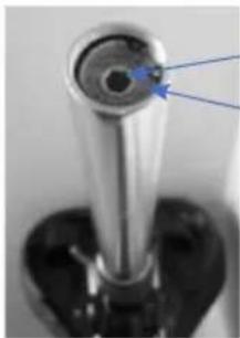
| Motor does not cut in Check connector plug | on left fork leg.Battery positioned correctly in frame? New battery fitted shows empty |
| Battery empty Forgotten to switch off system | ? Charge battery |
| Battery cannot be charged - LED on charging unit illuminated | Is the socket working? Is the charging plug inserted correctly in the charging port? |
| The specified range is not achieved The range will vary depending on the circumstances, such as rider weight, wind, terrain, slope up and down.A lower range is not an indication of a defective battery | |
Pedelec components - battery
Safety information

Please make sure you comply with the safety notices below. Failure to comply can lead to the risk of short-circuiting, fire and explosions as well as injuries.
- Only use the battery and charging unit supplied specifically for this Pedelec.
Regularly check the battery for any damage. A battery with a damaged housing must not be used any more. Replace the battery.
-
Keep the battery away from fire and heat. Never place the battery in the microwave.
-
Keep the battery away from water and moisture. Never clean it using a pressure washer or other water spray.
-
Keep all metal objects (e.g. nails, screws, metallic debris) away from the contacts of the battery and charging unit.
-
Avoid short-circuiting the battery.
-
Do not expose the battery to sharp shocks or prolonged vibration.
-
Never open or repair the battery. If the battery is damaged, replace it instead. For this, always use original accessories and spare parts from the manufacturer.
-
When transporting the Pedelec (e.g. car-mounted bike carrier) always remove the battery. During transport, do not expose the battery to sharp shocks or prolonged vibration. always make sure it is stored safely.
Maintenance and use of the battery
The battery used is a latest generation lithium-ion battery. This no longer has a memory effect, as was the case just a few years ago with NiCd cells.
This means you no longer need to fully discharge the battery prior to charging, and you can recharge the battery at any time irrespective of the charge level without incurring a loss of charging capacity. After every ride, the battery should be charged until the charging unit switches off.
Make sure that if the drive is not in use (also during breaks) the system is switched off. Otherwise the battery undergoes a deep discharge. This can lead to damage to the battery!
The battery is subject to a certain self-discharge. To ensure that the fill capacity is available for your ride, you should recharge the battery before starting your journey, irrespective of the charge level displayed.
You will significantly maintain the longevity of your battery by always making sure that the battery does not self-discharge. This means that during the winter months, the battery should be recharged once in a while, ideally in a cycle of 6-8 weeks. Never store the battery in a room which is exposed to large temperature fluctuations and below-zero temperatures. Your battery will be protected best if you store it at room temperature.
The battery should never be stored fully discharged!
Please note that the battery is one of the most high-tech and valuable parts of the Pedelec, for your own benefit it is important to look after it.

When removing and inserting the battery, the electrical system/the motor must be switched off.
Operation
| Battery type | Luggage rack battery | Frame battery Frame battery semi-integrated | Seat post battery |
| View | |||
| Inserting battery | Slide the battery into the bracket on the luggage rack. Lock the battery using the key. | Insert the battery into the frame bracket, until it engages. | Insert the battery into the frame bracket, until it engages. |
| Switching on | If the system has a main switch, set this to the "I" position. Press the on/off button, or keep it pressed for 2 seconds - depending on the system - to switch on the system. | Press the on/off button, or keep it pressed for 2 seconds - depending on the system - to switch on the system. | Press the on/off button, or keep it pressed for 2 seconds - depending on the system - to switch on the system. |
| Switching off | Press the on/off button or keep it pressed for 2 seconds - depending on the system - to switch off the system. If the system has a main switch, place this in the "0" position. | Press the on/off button or keep it pressed for 2 seconds - depending on the system - to switch off the system. | Press the on/off button or keep it pressed for 2 seconds - depending on the system - to switch off the system. |
| Removing the battery | Undo the lock using the key and pull the battery out of the bracket. | Undo the lock using the key and pull the battery out of the bracket. | Undo the lock using the key and pull the lever on the left side of the battery bracket at the same time to be able to remove the battery. |
Pedelec components - battery
Charging the battery

To charge, use the original charging unit. The use of other units will result in the battery cells being destroyed.
- When charging for the first time, allow the battery to charge for 24 hours.
To charge the battery, insert the charging unit plug into the charging port on the battery. Plug the charging unit into the wall socket. The correct charging function is indicated by the LED as follows:
Red = charging
Green = charging complete
Disposal

Batteries must not be disposed of with normal household waste. Every consumer is obliged to hand in old batteries at the relevant collection point in their community, city suburb or shop, to enable environmentally-friendly disposal.
Lithium batteries and battery packs should only be handed to the collection points once discharged. Precautions must be taken against short-circuits (e.g. by insulating the poles using adhesive tape).

Depending on the model, our Pedelecs are supplied with different LCD panels. For this reason, different systems are described below.

- Pay attention to your safety. Never disconnect the connection whilst the display is switched on.
- Avoid shock and impacts.
- Do not expose the display to moisture or rain.
- Do not use the display if it is defective.
1 KM529
Switching on/off
- To switch the system on, keep the
M button pressed for 2 seconds.
- To switch off the system, keep the
M button pressed once more for 2 seconds.

If the Pedelec is not used for more than 10 minutes, the system automatically switches off.
Selecting the assistance level
- Press the + button to increase the assistance level.
- Press the button to reduce the assistance level.
The levels range from 1 to 5 and are shown on the right hand side of the display. - Level 1-5 maximum speed settings are stepped as follows: 12 km/h,16 km/h,19 km/h,22 km/h and 25 km/h .
- When the E-bike is switched on, Level 1 is automatically selected.

The support increases linearly when pedalling, to allow gentle starting. This reduce the risk of losing traction.
Speed displays
The standard setting after switching on the display is speed display. Press the M and buttons together for around two seconds to change the information displayed in the following sequence:
Current speed (km / h) -> average speed (km / h) -> maximum speed
Pedelec components - control unit
Distance displays
The standard setting after switching on the display is the current distance ("Trip"). Press the M button to change the information displayed in the following sequence:
Current distance ("Trip") -> total distance ("Odo")
Resetting trip meter
To reset the trip meter, the display must be on "Trip".
Press the M and buttons at the same time to reset the display to 0.
Push assistance
Keep the button pressed to start the push assistance. For this, the display must be switched on.
Switching lighting on/off
- Press the + button for around two seconds to switch off the display lighting. The front light of the Pedelec is switched on at the same time.
- Keep the button pressed once more for two seconds to switch off the lighting once more.

This only applies for lighting coupled to the Pedelec system, not for Pedelecs with separately operated (wireless) lights. These must be switched on/off separately and charged with a micro-USB cable (not included in the scope of supply).
The rear light is operated with normal AA LR6 batteries.
Setting display brightness
You can adjust the display brightness in the menu point "BL".
- For this, press and hold the + and buttons at the same time. Using the + buttons select the desired value between 1 and 3, with 1 being the lowest and 3 the highest brightness.
The factory setting os 1. "bL" background lighting. - Confirm your selection using the M button, to close the settings menu.
2 KD21C
Switching on/off
- To switch the system on, keep the "MODE" button pressed for 2 seconds.
- To switch off the system, keep the "MODE" button pressed once more for 2 seconds.

If the Pedelec is not used for more than 10 minutes, the system automatically switches off.
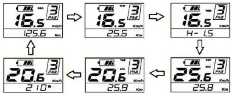
Display interface
After switching on the display shows the km travelled as well as battery level and assistance level. To change the display, briefly press the "MODE" button as shown below. Speed (Km/h) -> distance travelled (km) -> travel time (hour) -> maximum speed (km/h) -> average speed (km/h) -> motor power (W) -> current speed (km/h)
Push assistance
To activate push assist, press the minus button. The Pedelec then drives to 6km / h , without pedalling.
Light on/off
- To switch on the light, press and hold the plus button for 2 seconds.
- To switch off the light, proceed in the same way.
Changing assistance level
To select the assist level, press the plus or minus buttons on the display.
Resetting trip meter
To reset the trip meter, press the plus and minus button at the same time to select Y or N. The standard value is N.
Select Y and confirm using the "MODE" button to set the trip meter to 0.
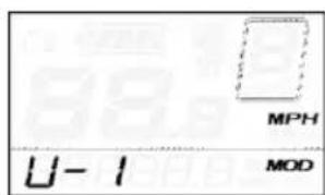
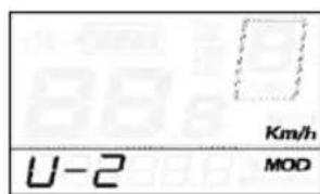
Setting km/miles
U means setting km or mile, "U-1" means miles, "U-2" means kilometres.
The standard setting is km (U-1).
To change the setting, press and hold the "MODE" button.
Then select one of the two options using plus or minus.
Confirm once more with the "MODE" button.
Pedelec components - control unit
Assistance level table
| 1 2 3 | 4 5 6 7 | 8 9 | |||||||
| 0-3 / 1-3 50% 74% | 92% - - | - - - - | |||||||
| 0-5 / 1-5 50% 61% | 73% 85% | 96% | - - - | ||||||
| 0-7 / 1-7 40% 50% | 60% 70% | 80% | 90% 96% | - - | |||||
| 0-9 / 1-9 25% 34% | 43% 52% | 61% | 70% 79% | 88% | 96% |
Meaning of symbols
| Symbol Definition | ||
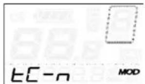
| 1 | EC | Trip meter |
| 2 | BL | Background lighting |
| 3 | U | Unit |
| 4 | VOL | Volt |
| 5 | LD | Rim size |
| 6 | LS | Limit |
| 7 | CGR | Controller overvoltage |
| 8 | FON-B | Backwards |
| 9 | FON-F | Forwards |
| 10 | SCH | Sensitivity of PAS sensor |
| 11 | SPS | Speed sensor |
| 12 | DLY | Power delay |
| 13 | HL | Push assistance |
| 14 | HF | Acceleration change |
| 15 | PUS | Press button |
| 16 | SSP | Slow start |
| 17 | PSB | Password |
| 18 | DEF | Standard setting |
| 19 | y | Yes |
| 20 | n | No |
3 Bafang
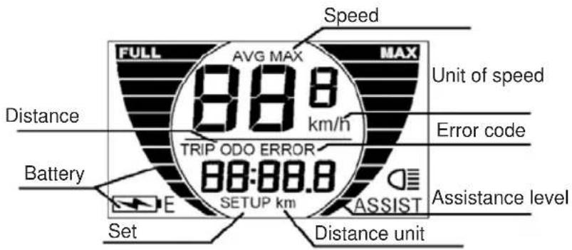
Description of the display
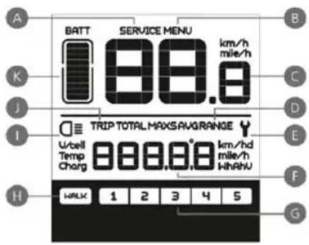
Explanation of the symbols
A. "Maintenance" indicator If maintenance is required, the "SERVICE" symbol appears. It shows that a certain mileage has been reached or exceeded, or a if a certain number of battery charges has been reached.
B. Menu (selection button)
C. Speed display km/h or mph (miles)
D. Display for average speed (AVG) or maximum speed (MAXS)
E. Display system faults. If this symbol appears consult your dealer.
F. Distance display - shows the range as a function of the selected settings
G. Display of the assistance level (1 to 5) of the motor. If no display appears, the motor is not providing any assistance. If the bike is pushed, the system detects this and displays WALKH. Display for walking or push assist
I. Display not available for your bike
J. Display for distance travelled: Trip meter and total distance
K. Battery information with 10-segment display; the voltage level represented by each segment can be adjusted individually
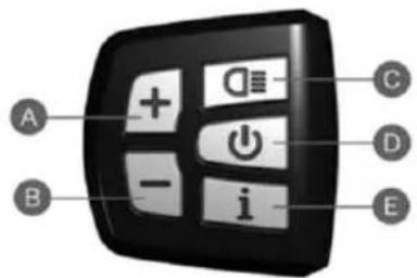
A. HIGHER
B. LOWER
C. not applicable
D. ON/OFF
E. Selection button
Switching on/off
Press and hold for 2 seconds - display is activated.
Press and hold for 2 seconds - display is deactivated. If the Pedelec is not used, the energy saving function is activated and the system switches off automatically. The switch-off time can be adjusted.
Assist mode
Once the system is activated, press plus or minus to select the desired motor assist level. The lowest level is 1 - the highest is 5. If the system is active, "1" is the default level. If no number is shown, there is also no motor assist.
Pedelec components - control unit
Switching between "mileage / trip" and "speed"
Briefly press , to switch between the display modes: Trip distance, total distance, maximum speed or average speed.
Push assistance
Press minus for two seconds - the E-bike enters the "push" = WALK mode, once the button is released, the push function is ended.
4 Ananda D13
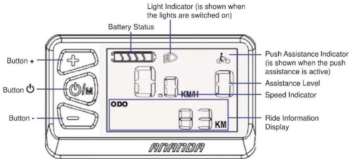
Switching On/Off
To switch the system on, press and hold the button M.
To switch the system off, press and hold the button M.
Note: If the system is not being used it will switch off automatically after 10 minutes.
Battery Status
- When all bars of the battery status display are shown the battery is fully charged.
- The fewer bars are shown, the lower the battery charge is.
Note: To protect the battery it should never be fully discharged. Charge the battery once two bars of the battery status display are remaining.
Assistance Level
The system offers 5 assistance levels.
- To select a higher assistance level, press the button + once.
- To select a lower assistance level, press the button - once.
- If "0" is set there will be no assistance.
Push Assistance
- Press and hold the button - while pushing to activate the push assistance.
Once the button - is released, the push assistance will be deactivated.
Lights On/Off
Note: This is only available when your pedelec's lights are connected to its system.
- To switch the lights on, press and hold the button +.
- To switch the lights off, press and hold the button + again.
Ride Information
While the system is switched on, press shortly and repeatedly the button O / M to show the following ride information in the display:
Total distance ridden (ODO)
- Trip distance (TRIP)
- Trip duration (TIME)
Max.speed(MAX SPEED)
Average speed (AVG SPEED)
To reset the above values (except total distance ridden) press and hold for about 5 seconds the buttons +/- simultaneously.
5 Ananda D15
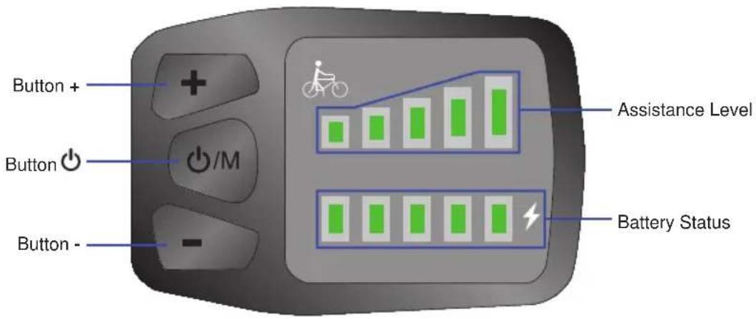
Switching On/Off
To switch the system on, press and hold the button
To switch the system off, press and hold the button
Note: If the system is not being used it will switch off automatically after 10 minutes.
Battery Status
- When all LEDs of the battery status display are lit, the battery is fully charged.
- If the left LED of the battery status display is flashing, the battery is empty and needs to be charged.
Note: To protect the battery it should never be fully discharged. Charge the battery once two LEDs of the battery status display are remaining.
Assistance Level
The system offers 5 assistance levels.
- To select a higher assistance level, press the button + once.
- To select a lower assistance level, press the button - once.
Pedelec components - control unit
Push Assistance
Press and hold the button - while pushing to activate the push assistance.
Once the button - is released, the push assistance will be deactivated.
Lights On/Off
Note: This is only available when your pedelec's lights are connected to its system.
- To switch the lights on, press and hold the button +.
- To switch the lights off, press and hold the button + again.
6 LED control unit

The control unit shown below is only for illustration purposes. The actual control unit on the Pedelec may look different.
Switching on/off
Press the ON/OFF button to switch on or off the control unit and the motor assistance.
Battery display
When the battery is fully charged the four LEDs on the battery level display are illuminated. If the left LED on the battery display flashes, this means that the battery needs to be charged.
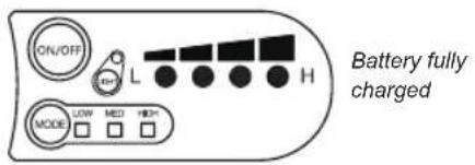
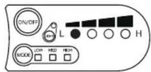
Left LED flashes: Battery needs to be charged
Switching front light on/off
Press the light button to turn the light on/off (not possible if the light is separate from the Pedelec system).

Front light switched on

Front light switched off
Motor assistance
This unit offers four levels of motor assistance. Press the button to switch between the available levels.
| Off No motor | LOW MED HIGH assistance | |
| LOW | LOW MED HIGH | Lowest assistance and economical battery use. |
| MED | LOW MED HIGH | Medium assistance. |
| HIGH | LOW MED HIGH | Highest assistance but also highest battery use. |
| Problem Possible | remedy |
| Clicking / grinding in bottom bracket area | Check the pedal threads; check the centre screw of the crank arm on the bottom bracket bearing (40Nm).Lubricate the motor guide spigot which projects into the frame (cutout frame/guide spigot). This is located on the bottom of the bottom bracket. Turn the bike upside down. |
| Lighting not working | Check the connection and contact of the cable plug connections on the front light, rear light and on the dynamo and if req. replace with new plug, check lights and if req. replaceCheck side-running dynamo: Contact with the tyre OK? If req. Replace tyre if the running surface is worn out. If req. Fit dynamo with replacement friction roller. |
| Brakes squeak/not powerful enough | Check the pad thickness of the brake pads, and replace if req.Check the position of the brake pads to the rim, set V-position(see maintenance). |
| Gears not changing correctly | Especially with derailleur systems, the cables stretch a little with use. Adjust using the fine adjusters directly on the brake lever, by unscrewing approx.2 turns. This increases the tension again. (Also see maintenance) |
| Gears (Shimano Nexus 7-speed) making noises | The adjustment is done using the knurled nut in front of the clickbox on the rear hub.Shift to fourth gear.The yellow-marked settings of the gearshift unit bracket and the roller must be aligned with eachother, otherwise annoying noises may be heard during riding or shifting problems may occur. Being aligned means that the markings match up. Possibly you may also need to push your chain guard a little to the side, to be able to see both lines better. Alternatively you can also look from below past the chain.If the adjusting lines do not match up please proceed as follows:On the gearshift turn the tension adjuster screw (black) to match up the setting lines correctly.Then shift from fourth to first gear and then back to fourth gear, and then check the position of the adjustment lines once more.Carry out a shift-intensive test ride.Incorrect setting Correct setting |
Self-help tips
| Electric drive not cutting in | Please check whether the pedal frequency sensor in the bottom bracket still has a spacing of max 3 mm from the magnetic disc. Please check whether the system switches on properly and the battery indicator light lights up (on the battery/ on the display) |
| The Pedelec battery does not charge | Check all plug connections. Check the fuse within the battery. Check whether the brake levers move freely - these are fitted with a switch so that the system switches off immediately if the brakes are operatedCheck the fuse in the battery. With the frame battery switch the key to position 1. The LED in the charging device lights up red when the battery is charging and green once charging is complete. Ideally charge and store the battery at room temperature, but never under 0 °C. |

Risk of shock and short-circuit!
Electrical hazards are present during care, maintenance and repair works.
- Unlock and remove the battery from the Pedelec.
- Disconnect the charging unit from the mains.
- New clean the components with running water or other liquids.
- Never use pressure washers or water jets.
Cleaning & care
Regular care means that your Pedelec will remain safe and reliable.
- Keep all electrical drive components clean.
- Clean the components with a lightly moistened cloth.
- Always use a mild detergent and never use solvent-based or other aggressive cleaning agents.
- When cleaning, pay attention to the electrical connections. Check whether all cables, connections and contacts are clean and free of damage (visual inspection).
- Prevent moisture or dirt entering the contacts.
Caring for the drive unit
The drive unit is maintenance-free. Care for the housing and connections as described above.
In case of problems please contact your specialist dealer.
Storage
When storing your Pedelec, please apply a preservative in the form of a suitable care product, so that corrosion is prevented as far as possible before it occurs. Make sure that rubber brake components and tyres do not come into contact with oil.
Please make sure you remove the battery and ensure that this is stored at room temperature.
Furthermore, completely charge all batteries every 2 months, to keep them in optimum condition.
Maintenance

- All repairs and maintenance work should only be carried out by a qualified specialist.
- Unlock and remove the battery from the Pedelec.
- Disconnect the charging unit from the mains.
Quick release clamps
For fast adjustment or assembly and dismantling most bikes/Pedelecs are fitted with quick release clamps. All quick release clamps must be check for tightness before every use of the bike/Pedelec. Quick release clamps should be operated with great care, since your safety directly depends on this.
Make sure you use the quick release clamps correctly to avoid accidents.
The quick release clamp essentially consists of two elements:
- Lever on one side of the hub: It converts the closing motion to clamping force via a cam.
- The clamping nut on the opposite side of the hub: This is used to set the pre-tension on a threaded bar (quick release axle).
Open the quick release clamp. Ensure that the component to be clamped is positioned correctly. Move the lever towards the clamping position so that "close" can be read from outside. From the start of the closing movement up to half the stroke the lever must be very easy to move. After this, the force on the lever should increase significantly and the lever should only move with difficulty at the end. Use the ball of your thumb and brace the fingers against a solid component, however not the brake disc or a spoke. In the final position, the lever should be at a right angle to the quick release axle. I.e. under no circumstances should it project outwards. The lever should lie along the fork or the frame so that it cannot open inadvertently. It should also be east to reach however, so that it can indeed be operated quickly.
Check for firm seating by pressing the end of the closed lever and attempting to turn it. If it moves, you must open it and increase the pre-tension. Turn the clamping nut on the opposite side clockwise half a turn. Close the quick release clamp and check the tightness once more.
Frame
The frame of your bike is coated with a high-quality paint system, which enables particular brightness of the colours due to wet-coating, and by sealing with a plastic-based clear powder coating layer provides excellent impact-resistance.
Depending on the model, the frame number can be found either on the steering head or on the underside of the bottom bracket.
Please care for the frame as well as all fittings with a standard commercial bicycle care oil as per the instructions from the oil manufacturer. Always consider that environmental factors expose your bike to special loading. In particular air containing salt or ammonia require more regular care and protection of the paint and all fittings.
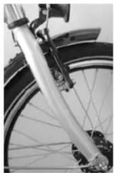
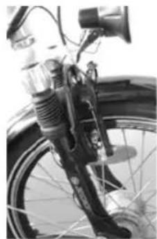
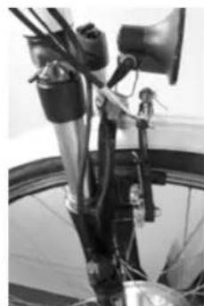
Forks
Depending on the desig, your bike is fitted with one of the following forks:
Rigid Unicrown fork Suspension forks with
elastomer/spring damping
Adjustable suspension forks with
lock-out and adjustment
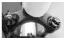
Suspension seat post
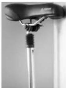
If a suspension seat post is fitted to your bike, the spring comfort can be set using the adjusting nut.
For harder suspension turn the nut to the right, for softer suspension to the left.
Please ensure in all cases that the complete thread of the adjusting nut remains in the suspension seat post.
This is secured against turning out completely using a circlip. If you remove the circlip and completely unscrew the adjusting nut, open the post and you have full access to the spring, which is not required under normal circumstances.
Adjusting nut
Circlip
Maintenance
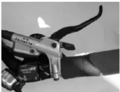
Brakes
Depending on the design and equipment of the bike we use the following types of brakes:
Hand brakes:
Adjusting screw
Screw
An adjusting screw is located on the brake lever to allow fine adjustment of the brake cable tension.
With normal muscle-powered bikes, there is a screw for adjusting the zero position of the lever. This adjustment is provided to adjust the lever if you have especially small hands.
This means you always have safe access to the brakes.
To adjust, undo the brake cable on the brake unit, screw in the zero point screw further until the desired position is reached, then fix the brake cable to the brake unit once more.
Make sure that the brake lever has spare travel - when the brakes are fully on, the lever must not contact the handlebar grip.
For Pedelecs we usually use brake levers with a switch which immediately cuts the electric assist when the brake lever is operated.
Brakes are critical components. Check the brakes before every ride and if worn only use components of the same type and quality. If in doubt always consult a specialist bicycle dealer!
Safe use of brakes is an important part of your safety when riding.
For this reason, it is essential to become familiar with the brakes of your E-Bike before your first ride. Risk of accidents!
Before every ride check your brakes for correct function. Incorrectly set or poorly repaired brakes can result in reduced braking power or complete brake failure. Risk of accidents!
The braking performance depends on many factors. It may be significantly reduced e.g. due to ground conditions (gravel roads, chippings etc.), additional loading, downhill riding or adverse weather conditions.
On wet surfaces the braking distance may be around approx. 60% longer than on a dry surface. For this reason, adjust your riding accordingly. Ride more slowly and with special care. Risk of accidents! Avoid sudden and heavy braking to prevent possible slipping or locking of the wheels. Risk of accidents!
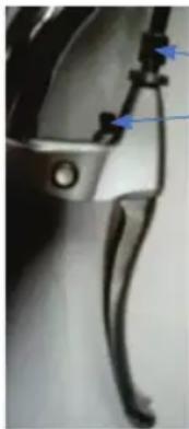
Replacing the brake shoes
In order to access the brake pads, the brake arms must first be unclipped. With V-brakes to do this, the tops of the brake arms are pushed together. This reduces the tension on the Bowden cable and it can be released from the cross-piece of the brake. The Bowden cable now hangs on one brake arm and the other brake is open. It works similarly with cantilever brakes: The cross-pull, which usually leads to the left brake arm must be released from the suspension point. In this case again the two upper brake arms need to be pushed together to remove the tension from the Bowden cable. The brake is now open.
With V-brakes and cantilever brakes the open brake now allows access to the brake shoes which are attached to the brake arms with hex screws. The screws can be undone with a normal hex key. With many brakes, various washers
allow alignment with the wheel rim. In order to be able to reassemble the brake perfectly again, it is important to note the sequence of the different washers.
With disc brakes, the brake pads are removed by turning the hex head screw which holds them in the brake caliper. These can then be pulled out.
Only use original manufacturer's spare parts. If in doubt contact your local specialist dealer. The brake shoes with new pads are then inserted into the brake arm. Make sure that the washers are installed in the correct sequence. Then tighten the screw so that the brake shoe is seated securely but can still be moved slightly.
After this, the brake is reattached for alignment. When doing so bear in mind:
- When braking, both pads should contact the wheel. Here, the front part of the brake pad should contact the rim first to prevent squealing during braking and to optimise the braking performance.
- The perfect distance between brake pad and rim is 1.5 to 2mm .
- The brake pads should not touch the tyres, since this will damage the tyres.
With disc brakes, the brake pads must be pressed together and in this position must fit exactly into the brake caliper. These are then fixed again using the hex screw
via brake cable
Here the force is transmitted from the lever to the disc via a conventional brake cable.
Depending on the brake use, the brake pads are
designed for a long service life. Since these are
always type-specific however, please order your spares
using the article number of the
bike you purchased.
Work on brakes should be carried out by a specialist. Incorrect assembly can lead to brake failure.
Risk of crashing!
via hydraulic cable
Here the force is transferred via a closed system using brake fluid.
The brake lever is fitted with a supply tank from which brake fluid is pushed to the brake cylinder by pressing on the lever.
Maintenance
The brake disc is fitted on the wheel hub, and creates the braking forces.
Due to the density of the fluid, force losses in this system are substantially lower than with a cable system.
Back-pedal brake
Depending on the design, the back-pedal brake is integrated into the gear hub and is simply activated by pedalling backwards. Due to the fact that it is not affected by weather this type of brake is very efficient.
Wheels
When manufacturing our wheels, we normally use aluminium rims, depending on the design, box- or double-wall hollow chamber rims, galvanised or stainless spokes, aluminium-/steel freewheel hubs, branded back-pedal brakes, branded Pedelec motors, tyres with an appropriate profile, reflective ring/ spoke reflectors.
If you require replacement tyres, please ensure that the correct tyre size is used. This is printed on the side of the tyre and has the following meaning:
28^ × 1.75 (traditional imperial size)
is equivalent to
47-622 (47 is the tyre width in mm, 622 is the tyre diameter in mm)
If your Pedelec is fitted with a tyre with a reflective sidewall, please use the same type since
2 additional spoke reflectors would be required per wheel to gain StVZO approval.
When inflating, ensure that the maximum pressure printed on the side of the tyre is never exceeded.
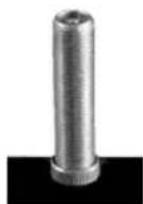
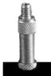
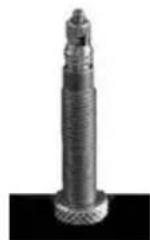
The different valves require different adapters for one air pump.
Car valve Dunlop valve Presta valve
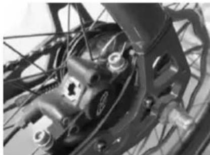
If you need to remove the wheel, e.g. to change the tyre or tube, first undo the axle nuts. Then press the V-brake arms together by hand so that you can unclip the brake cable out of the holder on the right brake arm. Then you can remove the wheel. After changing the tyre, please reassemble in the opposite order. Note the tightening torques below.
Gears
In terms of gears, there is a fundamental distinction between 2 different systems, derailleur gears and hub gears. Depending on the version, a hub gear can be combined with a back-pedal brake. A derailleur gear is always without back-pedal brake.
Derailleur gears
You can recognise a derailleur gear by the sprocket on the back wheel (cogs) with 5-10 gearwheel, and a rear derailleur mechanism, and at the front a chain ring with 1-3 rings and a front derailleur. Chain wheels on the cranks (the larger the chain wheel the greater the resistance), sprocket on the rear wheel (the smaller the cog, the greater the resistance). Increased resistance allows an increased top speed. Make sure you select the right gear for starting off or for hills.
You can work out the number of gears on your bike by multiplying the number of front chain rings by the number of rear cogs, for example 21 gears.
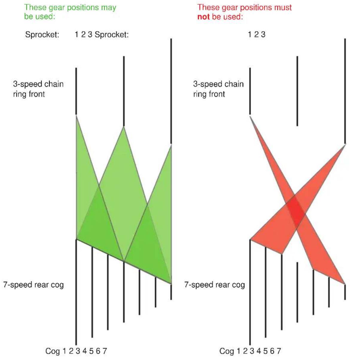
To protect your chain and gears, the chain should not run in an excessively diagonal position.
This increases the wear.
The combinations which should not be used do not represent a loss of function, since they are really theoretical.
Function and operation
A derailleur always functions according to the following principle:
Large chain ring at the front = harder gear, larger ratio
Small chain ring at the front = easy gear, smaller ratio
Large sprocket on the rear = easy gear, smaller ratio
small cog at the back = harder gear, larger ratio
The gear shifters are usually fitted as follows:
Right shifter: rear cog
Left shifter: Front chain rings
The chain is poorly positioned if it is on the smallest chain ring at the front while at the same time being on one of the three outer (smallest) cogs at the back, or if it is on the largest chain ring at the front and on the inner (largest) cogs of the rear wheel.
Maintenance
The bottom bracket is the interface between the cranks and the frame. Different designs exist - sometimes the shaft with bearings is part of the bottom bracket, sometimes it is integrated into the right hand crank. The sealed ball bearings are factory-sealed and -adjusted to have no play. The firm seating of the bottom bracket in the frame must be checked regularly.
Also check regularly that the cranks are fixed firmly to the bottom bracket axle or whether the bearings have play. If you wobble the cranks hard, no play should be felt. If this is the case, consult your specialist dealer immediately.
Depending on the system installed, a gear change process begins with operating a shift lever on a brake-gearshift unit or by a small turn of the wrist for a grip-shift switch. It is important to keep pedalling during the complete gear change process. The pedalling force should be reduced somewhat however.
An important point and reason for fitting a derailleur gear system with a higher number of gears is generally the greater range, i.e. the more gears, the easier the first gear will be and the higher the top speed in the highest gear.
Since the derailleur system is a highly complex external system, we urgently recommend cleaning and treating it with a chain lubricant on a weekly basis.
A derailleur system can become poorly adjusted very quickly in particular due to cables stretching.
Readjusting however is very simple and can be done using 2 stop screws and a knurled nut.
Adjustments can only be made if you keep the system moving while shifting. An important pre-requisite is that both the rear mechanism and also the front mechanism must move freely. Proceed as follows:
Then check that the front gear shift mechanism moves freely. To do so place the rear gear mechanism in a central position (for example cog no. 4), turn the cranks and shift the left gear lever through the positions 1-2-3.

Position 1 = chain ring 1
Position 2 = chain ring 2
Position 3 = chain ring 3
Knurled nut for fine adjustment
If the chain cannot be moved to all 3 chain rings, the corresponding stop screw must be screwed further out. If the chain overshoots, the corresponding screw must be screwed further in.
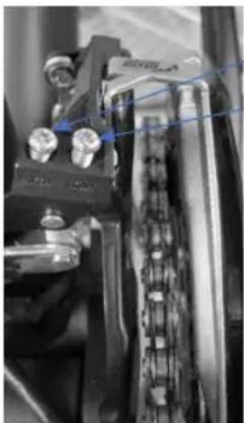
Stop screw "High" = for large chain ring
Stop screw "Low" = for small chain ring
To check for free movement place the shift lever in position 1 and press the derailleur mechanism into position 3 with your thumb, whilst turning the cranks.
If the alignment is then not correct, move the knurled nut on the shift lever to the right to move the mechanism further towards the small chain ring 1, and to the left to move the mechanism further in the direction of the large chain ring 3.
Then shift the lever to position 2 so that the chain runs on the centre chain ring at the front, therefore allowing easy adjustment of the rear gears.
Carry out the adjustment of the rear mechanism as follows:
Then check that the gear shift moves freely. To do so, move the grip-shift to the smallest cog, which is also the highest gear. Then try to press in the mechanism by hand whilst turning the cranks until the chain runs onto the largest cog no. 1. If this does not work, you need to undo the stop screws. If the chain "overshoots", i.e. jumps off the cog, the corresponding screw must be screwed in further.
Maintenance
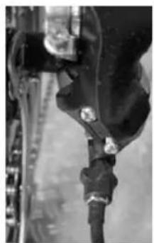
Stop screw "H" for smallest sprocket
Stop screw "L" for largest sprocket
Knurled nut for fine adjustment
Once free movement is established, the fine adjustments can be made. To do so, shift to 1^st gear (i.e. the largest cog on the sprocket) and the turn the grip-shift to position 2 for the 2^nd gear.
If the chain then does not jump onto the 2^nd sprocket, turn the knurled nut 12 to 1 turns to the right, i.e. in. Then select 1^st gear once more. Then repeat the gear change on the 2^nd gear. If the chain now slides to the 2^nd sprocket, continue with the 3^rd up to the last gears in the same way. Then change back from the last gear, gear by gear to the 1^st gear. If req. you may need to turn the knurled nut back to the left a little once more. It is important that you proceed gear by gear, thus setting the optimum position of the knurled nut.
The settings for other grip-shifts should be done analogously. Irrespective whether Rapid Fire lever, thumb-shifters or grip-shifts, the principle for adjustment is always the same in principle.
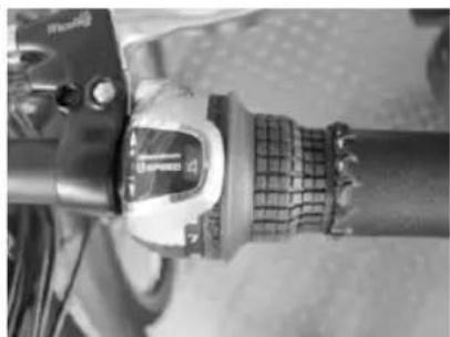
Hub gears
Hub gears are fundamentally different in design to derailleur systems, and the maintenance requirements as well as adjustment potential are substantially less.
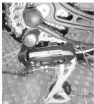
A specific manufacturer's description is available for every hub gear system, but in principle only the position display on the grip-shift needs to be matched to the position in the hub. For this, a gear is marked on the grip-shift, e.g. 4^th gear. At the back on the hub where the cable enters, there is also a mark which needs to match.
Examples:
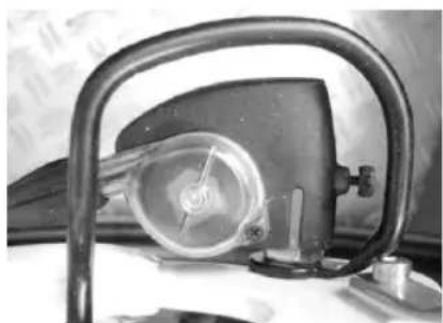
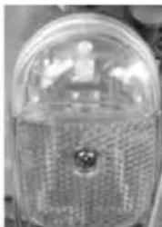
SRAM S7 speed hub gear:
The adjustment is done using the knurled nut in front of the clickbox on the rear hub.
Shift grip marking 4^th gear
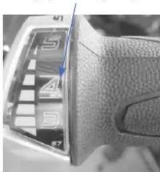
Clickbox marking 4^th gear
Lighting system
We make a fundamental distinction between 3 types of bikes with respect to the lighting systems.
Bikes without lights
Bikes without lights are not suitable for use on the public roads. The bike must not be used in the StVZO area.
Bikes with lights
The bikes are equipped with StVZO-compliant lights. The lights have a minimum brightness of 10 Lux, the dynamo provides 6 Volts and 3 Watts.
The rear light is generally fitted with an automatic stationary lighting system, with versions either using a capacitor or a battery.
The battery version has the advantage that the stationary light function is already available following the first short period of power supply from the dynamo. The rear stationary light is then illuminated for approx. 4 minutes, so that for example the rider is always seen immediately by road users from behind at traffic lights. The battery must be replaced however once it no longer has sufficient voltage. This is shown by an indicator light.
The capacitor version charges during riding, and after a distance of approx. 2-3 km also illuminates for approx. 4 minutes. The required reflectors are also mounted on the bike (also see legal requirements)
Bar / mudguard rear light Luggage rack rear light Front light

with hub dynamo
The modern hub dynamo provides the power source. It is not sensitive to weather, virtually wear-free and low maintenance.
Maintenance

The lighting system is activated easily by a central switch on the rear of the front light.
Chain & chain tension
To test the chain tension, your specialist dealer will have precise measurement equipment.
The replacement of the chain should be done by a specialist, since it requires special tools and a chain must be selected which fits to the relevant gear system.
To tension the chain, undo the quick release clamp on the rear wheel and then pull the wheel backwards slightly until the optimum chain tension is achieved. When tensioned optimally, the chain should sag by around half a centimetre. It must be possible to press it approx. 3 cm upwards or downwards easily. After centering the wheel, retighten the quick release clamp once more.
The side stand is provided to prevent the Pedelec falling over when parked. Make sure that the Pedelec stands in a stable position. Stable ground is essential for this (e.g. asphalt). When parking the bike on soft surfaces (gravel, grass) the bike will not have a firm base.
Tightening torques
Please make sure that the screws on the bike are tightened with the following torques before you ride:
Component Screw connection Torque
Axle nuts Front wheel cap nuts 20 Nm
Rear wheel cap nuts 25 Nm
Crank Fixing screws 30 Nm
Brake block Nuts 5 Nm
DynamomountNuts10Nm
Other screws M4 2.1 Nm
M5 4.2 Nm
M6 7.3 Nm
M8 17 Nm
M10 34 Nm
In order to maintain its value, we strongly recommend you care and maintain your Pedelec, and ensure that worn or defective components are replaced immediately.
If req. any repairs will be identified as part of an inspection.
For this reason, arrange for it to be carried out by a specialist.
Please use the inspection proof section in this handbook to record proof of caring for the bike, and have this confirmed by a specialist dealer.

Warranty or guarantee may be refused in case of damages caused by non-compliance with the maintenance plan and its corresponding maintenance work.
| Maintenance plan | ||||
| Component Activity Before every ride | During every inspection | Other | ||
| Lighting Check function x x | ||||
| Tyres Check air pressure | x x | |||
| Brakes (rim) Check lever motion, brake block thickness | x x | |||
| Brakes (hydraulic rim) Check lever motion, brake block thickness | x x | |||
| Brakes (drum) Lever motion, stationary brake test | x x | |||
| Brake cables Clean | x | |||
| Brakes (discs) Visual check | x | |||
| Suspension forks | Check, re-tighten screws; major service (change oil) | |||
| Rims (with rim brakes) | Check wall thickness | x At the latest | after the 2ndset of brake pads | |
| Fork (rigid) | Check if req. replace | x min. every 2 | years | |
| Internal bearing | Check bearing play dismantle and regrease | x | ||
| Chain | Check and/or lubricate | x x From 1,000 | km or 50 operating hours | |
| Telescopic seat post | Maintain | x | ||
| Crank | Check if req. tighten | x | ||
Maintenance
| Paint/anodising/ carbon | Preserve x Min. | every six | months | |
| Wheels/spokes Check | check runout and tension if req. retension | x As required | ||
| Handlebars and stem check if req. replace | x At the latest | every 2 years | ||
| Headset Check bearing play; regrease | x | |||
| Hubs Check bearing play; regrease | x | |||
| Pedals Check bearing play | x | |||
| Gears/ mechanism | Clean/lubricate x | |||
| Bolts/nuts Check or retighten | x | |||
| Valves Check seating x x | ||||
| Cables/gears/ brakes | Check if req. replace | x | ||
When lubricating and greasing only use suitable products:
Bearings: Bearing grease
Chain: Chain oil
Bowden cables: Bicycle oil / Teflon lubricant
Hubs: Special grease
Ensure that the lubricants do not contain any corrosive substances or alcohols.
Proof of inspection
EN
1. Inspection
After 3 months
Work completed / comments:
Materials used:
Date:
Signature:
Dealer stamp
2. Inspection
After 6 months
Work completed / comments:
Materials used:
Date:
Signature:
Dealer stamp
3. Inspection
After 12 months
Work completed / comments:
Materials used:
Date:
Signature:
Dealer stamp
4. Inspection
After 18 months
Work completed / comments:
Materials used:
Date:
Signature:
Dealer stamp
5. Inspection
After 24 months
Work completed / comments:
Materials used:
Date:
Signature:
Dealer stamp
6. Inspection
After 30 months
Work completed / comments:
Date:
Signature:
Dealer stamp
7. Inspection
After 36 months
Work completed / comments:
Materials used:
Date:
Signature:
Dealer stamp
8. Inspection
After 42 months
Work completed / comments:
Materials used:
Date:
Signature:
Dealer stamp
9. Inspection
After 48 months
Work completed / comments:
Materials used:
Date:
Signature:
Dealer stamp
1
1
一
一
Cher client, chere clientele,
Activation/désactivation
Activation/désactivation
Position 1 = plateau 1
Position 2 = plateau 2
Position 3 = plateau 3
Nominate spanning: 36V DC
Rood = laden is bezig
| 1 2 3 | 4 5 6 7 | 8 9 | |||||||
| 0-3 / 1-3 50% 74% | 92% - - | - - - - | |||||||
| 0-5 / 1-5 50% 61% | 73% 85% | 96% | - - - | ||||||
| 0-7 / 1-7 40% 50% | 60% 70% | 80% | 90% 96% - - | ||||||
| 0-9 / 1-9 25% 34% | 43% 52% | 61% | 70% 79% 88% 96% |
- Entsorgung
- Owner Purchaser
- Contents
- Wishing you a safe and pleasant ride!
- Notes regarding this handbook
- Introduction & important information
- Intended use
- Special notes for Pedelecs
- Pedelec applications
- Notes on battery and charging unit
- Information on lighting
- Information on the total weight
- Information on the manipulation of the electric system
- Information on the first ride with electric assistance
- Key data regarding the Pedelec
- Safety information
- Special information
- Product liability/ statutory warranty
- Disposal of waste electrical and electronic devices
- Design of a Pedelec
- Mountain bike - Hardtail
- City bike
- Assembly information / before the first ride
- Stem/handlebar
- Installing pedals
- Tightening torque: 35 Nm
- Adjusting the saddle
- Gears/brakes
- Lighting
- Tightness of all screws
- Folding frame
- Pedelec components
- Pedelec components - battery
- Maintenance and use of the battery
- The battery should never be stored fully discharged!
- Disposal
- KM529
- Switching on/off
- Selecting the assistance level
- Speed displays
- Pedelec components - control unit
- Distance displays
- Resetting trip meter
- Push assistance
- Switching lighting on/off
- Setting display brightness
- KD21C
- Display interface
- Light on/off
- Changing assistance level
- Setting km/miles
- Bafang
- Assist mode
- Ananda D13
- Battery Status
- Assistance Level
- Lights On/Off
- Ride Information
- Ananda D15
- LED control unit
- Battery display
- Switching front light on/off
- Motor assistance
- Cleaning & care
- Caring for the drive unit
- Storage
- Maintenance
- Quick release clamps
- Frame
- Depending on the model, the frame number can be found either on the steering head or on the underside of the bottom bracket.
- Forks
- Suspension seat post
- Brakes
- Brakes are critical components. Check the brakes before every ride and if worn only use components of the same type and quality. If in doubt always consult a specialist bicycle dealer!
- Replacing the brake shoes
- Back-pedal brake
- Wheels
- Car valve Dunlop valve Presta valve
- Gears
- Derailleur gears
- Hub gears
- Lighting system
- Chain & chain tension
- Tightening torques
- For this reason, arrange for it to be carried out by a specialist.
- Proof of inspection
- Inspection
- Materials used:
- Date:
- Inspection
- Inspection
- Inspection
- Inspection
- Inspection
- Inspection
- Inspection
- Inspection
- Activation/désactivation
Brand : TELEFUNKEN
Model : Kompakt F810
Category : Electric bike