Pluto Fresnel - Lighting Astera - Free user manual and instructions
Find the device manual for free Pluto Fresnel Astera in PDF.

| Brand | Astera |
| Model | Pluto Fresnel (AF80) |
| Product Type | Professional LED Fresnel |
| LED Engine | Titan LED |
| Colors | RGBMintAmber |
| Total LED Power | 105 W |
| Max Power Consumption | 80 W |
| CRI (Ra) / TLCI | ≥96 (3200-6500 K) |
| Beam Angle | 15° - 60° (adjustable) |
| Strobe | 0 - 25 Hz |
| Battery Runtime (Standard) | Up to 20 h |
| Battery Runtime (Full Power) | 3 h |
| Power Supply | 24 VDC, 80 W, 5.5 x 2.1 mm connector |
| Control | Screen + TouchSlider, IR, Wired DMX, Wireless CRMX, Bluetooth, WiFi, RDM |
| Protection Rating | IP55 (with cap or suitable cable) |
| Operating Temperature | 0 - 40 °C |
| Weight (with lens and barn doors) | 4.637 kg |
| Dimensions (L x W x H) | 281.9 x 153.5 x 161.8 mm |
| Housing Material | Polymer and metal |
| Included Accessories | Fresnel lens, 8-leaf barn doors, yoke, YokeBases, TVMP adapter, TrackHandle, waterproof cap |
| Safety | Use a safety cable when suspending, do not look directly into the light |
| Maintenance | Clean with a soft damp cloth, avoid solvents |
| Repairability | Replaceable battery (original part), non-replaceable LED |
Frequently Asked Questions - Pluto Fresnel Astera
User questions about Pluto Fresnel Astera
0 question about this device. Answer the ones you know or ask your own.
Ask a new question about this device
Download the instructions for your Lighting in PDF format for free! Find your manual Pluto Fresnel - Astera and take your electronic device back in hand. On this page are published all the documents necessary for the use of your device. Pluto Fresnel by Astera.
USER MANUAL Pluto Fresnel Astera
natural_image
Black optical laser headlight with three blades mounted on a stand (no visible text or symbols)User Manual
Benutzerhandbuch
Manuale utente
Manual del usuario
The PlutoFresnel from ASTERA is a LED Fresnel for professional use in the event and film industry. The PlutoFresnel is designed for direct or indirect illumination of objects and people. Due to its built-in battery it can be quickly set up at places where traditional lights cannot be mounted easily. It has the Titan LED Engine and offers excellent color and light qualities. The PlutoFresnel generates white or colored light and the color temperature can be adjusted in many ways. It can be controlled with the AsteraApp or with wired DMX or wireless CRMX. It is also possible to view and change settings via wireless RDM. The fixture can also be controlled by the integrated display or by infrared remote control. Thanks to its built-in Bluetooth it can be used as BluetoothBridge (BTB).
The PlutoFresnel can be used standing or hanging. For this purpose, the device is equipped with AirlineTracks to attach the appropriate mounting accessories. The PlutoFresnel can be used indoors and outdoors and has an IP55 rating.
Do not shake the device. Avoid brute force when installing or operating the device. When choosing the installation spot, please make sure that the device is not exposed to extreme heat or dust. Avoid direct sunlight for longer periods of time. The specified ambient temperature must be maintained. Keep away from direct insulation (particularly in cars) and heaters. Never use the device during thunderstorms connected to the power mains. Over voltage could destroy the device. Always disconnect the device during thunderstorms. Make sure that the area below the installation place is blocked when rigging, derigging or servicing the fixture. Always fix the fixture with an appropriate safety wire.
Operate the device only after having become familiarized with its functions. Please consider that unauthorized modifications on the device are not allowed due to safety reasons! If this device is operated in any way different from what is described
in this manual, the device may suffer damages and the warranty may be void. The disclaimer includes all damages, liability or injury resulting from failure to follow the instructions in this manual. Furthermore, any other operation may lead to dangers like short circuit, burns, electric shock, crash etc. This device is not for household use and is not suitable for permanent installation.
SAFETY INFORMATION
Before you operate this unit read the manual carefully. Always make sure to include the manual if you pass/rent/sell the unit to another user. Please use your own caution when operating. This product is for professional use only. It is not for household use.

- Do not operate the unit in areas of high temperature conditions or under direct sunlight. It can cause abnormal behavior or damage the product.
- Always use a suitable safety wire when mounting the light overhead.
- Connect the safety wire only to the intended safety mount.
• Always follow local safety requirements.
LI-ION Battery: A rechargeable lithium ion battery is built into this unit.
- Only authorized personal may service the battery.
- Do not place in fire or heat.
- Do not use or charge the light if it is damaged.
- Avoid bumping or plunging, it may cause fire or explosion.
- Never store the battery when fully drained. Always recharge immediately when empty. Please do not charge unattended.
- Make sure to fully charge all units before storing them.
- Partially charged batteries will lose capacity.
- Fully recharge every 6 months if not used.
- The battery may only be replaced with an original spare part from Astera.
- Follow applicable laws and regulations for transport, shipping, and disposal of batteries. For details on recycling lithium, lithium-phosphate, and lithium-ion batteries, please contact a government recycling agency or your waste-disposal service.
- Always charge with flight case open. - It is recommended to charge at a temperature between 15^ and 35^ .
Warning: In extreme cases, abuse or misuse of standard/rechargeable batteries can lead to:

- Explosion
- Fire development
• Heat generation or smoke and gas development
- Do not look directly into the light.
• It can cause harm to your eyes. - Do not look at the LEDs with a magnifying glass or any other optical instrument that may concentrate the light output.
- Use only Astera approved accessories to diffuse or modify the light beam.
- Do not open the product housing.
- Do not apply power if the light is damaged.
- Do not submerge the light into any liquid.
- Do not replace the LED light source.
- Caution, risk of electric shock.
The PlutoFresnel shall be installed near a socket-outlet which must be easily accessible. Warning: risk of electric shock - Do not open device.
- The exterior surfaces of the light can become hot, up to 70^ C (158°F) during normal operation.
- Ensure that accidental physical contact with the device is impossible.
• Install only in ventilated locations. - Do not cover the light.
- Allow all lights to cool before touching.
- Keep 0.3 m (12") from objects to be illuminated.
SECONDARY SAFETY MOUNTING

The PlutoFresnel must always be secured by a safety wire when used in a hanging position. If the primary suspension fails, the device must not fall more than 20cm.
natural_image
Technical line drawing of a mechanical assembly with no visible text or symbolsCLEANING AND MAINTAINING

Caution: Liquids entering the housing of the device can cause a short circuit and damage the electronics. Do not use any cleaning agents or solvents. Only clean using a soft damp cloth.
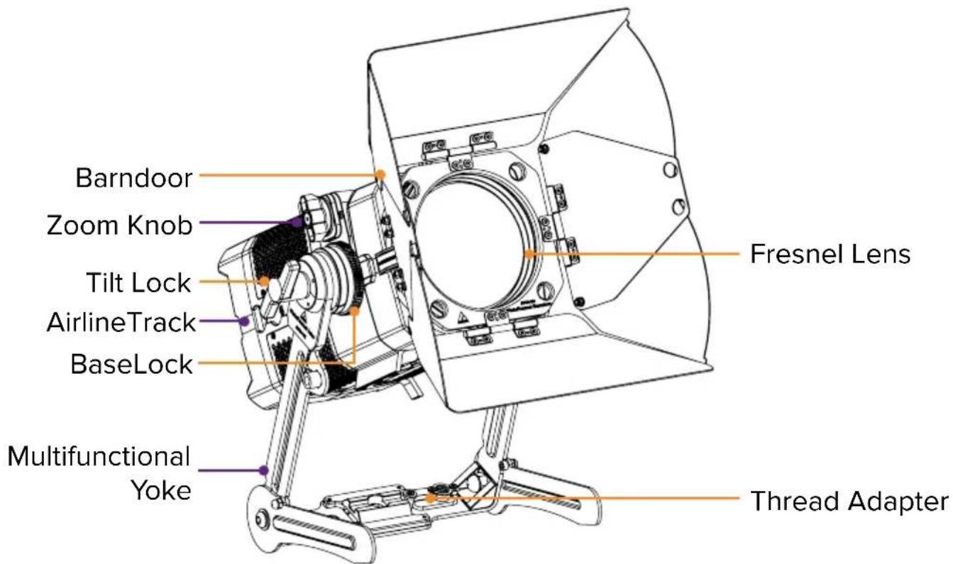
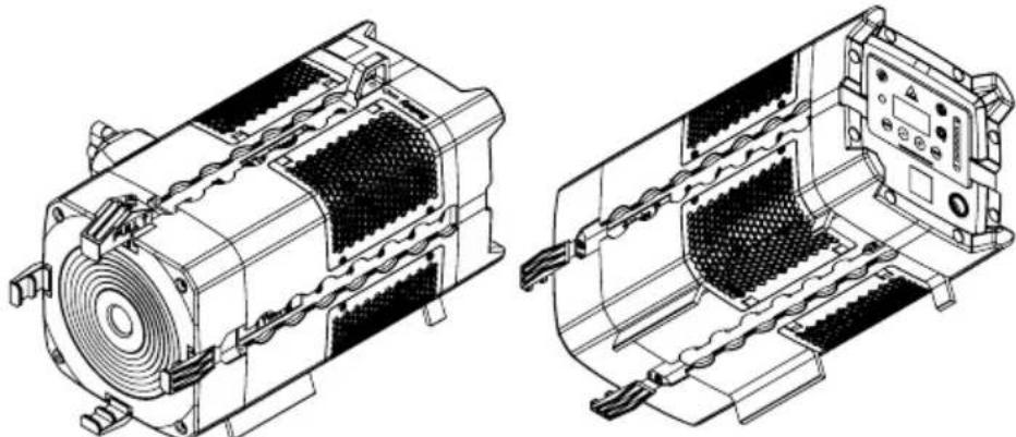
PRODUCT OVERVIEW
Isometric view
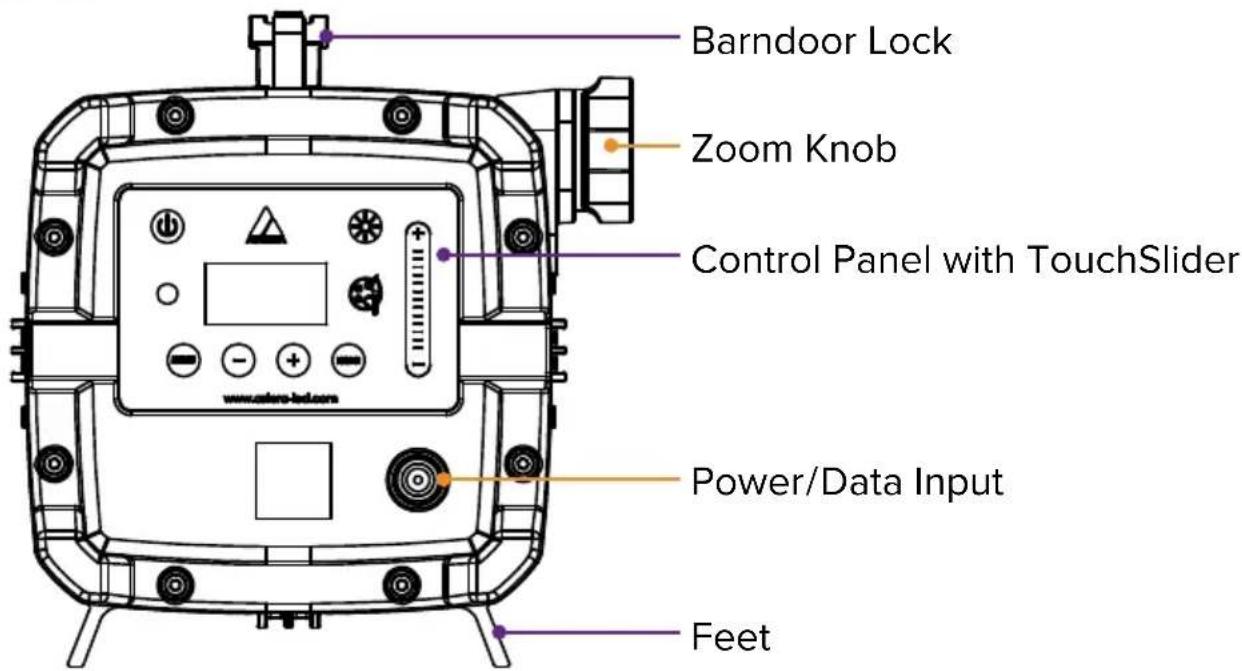
Back view
USAGE
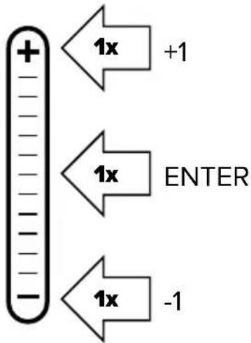
1. Integrated control panel
Use the menu buttons to navigate through the main menu. Settings for color adjustment and brightness / runtime are directly accessible by two symbol buttons.
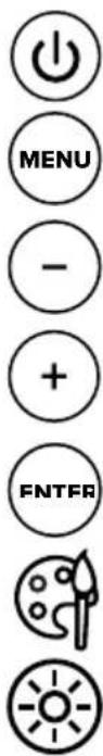
| Top navigation Inside main menu | |
| On / Off | |
| Main menu Back to previous menu | |
| Reset settings Scroll down | |
| Change input select Scroll up | |
| Set DMX address Choose / Confirm | |
| Color adjustment | |
| Brightness and runtime control | |
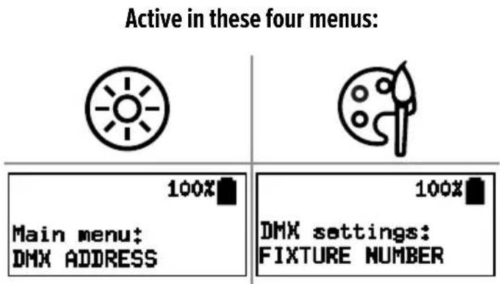
TouchSlider
The PlutoFresnel has a touch slider. It is only active in certain menus and can also be operated by tapping.
2. Switching On / Off
A new PlutoFresnel needs a few seconds of charge to disable its shipping mode before it can be switched on.
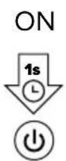
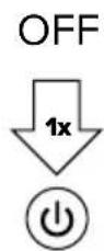
Press the power button for one second and release it to turn on the PlutoFresnel. When you press the power button to turn on the light, the display will not turn on until you release the button. To turn off the light, press the power button once.
3. Fan control
The PlutoFresnel has a built-in fan that can be controlled as follows. Navigate to Fan Control menu. There you can choose between the following settings:
OFF: The fan always remains switched off. If the light becomes too hot, the brightness is gradually reduced. (Ambient temperature dependent)
AUTO: The fan starts on demand and switches between the three speeds as required. This is the default setting.
LOW: Different speeds. The light never changes them by itself, but if the speed
MED: is too low, the brightness is gradually reduced. (Ambient temperature
HIGH: dependent)
4. More control options

On/Off, Static Colors, Preprogrammed Effects

All settings, Complex effects, Talkback+, Updates
Control from DMX consoles via CRMX or Wireless DMX
Control from DMX consoles via Power/Data Combination Cable

Remote Device Management (RDM) wireless
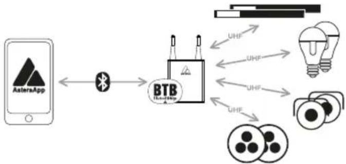
5. Connect Bluetooth Bridge (BTB)

flowchart
graph LR
    A["AsteraApp"] <--> B["Bluetooth Bridge"]
    B --> C["BTB BluetoothBridge"]
To control your lights with the AsteraApp, first connect a Bluetooth Bridge (BTB). It forwards the AsteraApp signal to paired lights. You may use an AsteraBox as BTB or choose a light with built-in BTB, like PlutoFresnel, AX9, NYX Bulb, PixelBrick, Titan Tube BTB, Helios Tube BTB.
Connect AsteraBox as BTB
flowchart
graph LR
    A["AsteraApp"] <--> B["BTB"]
    B --> C["UHF"]
    B --> D["UHF"]
    B --> E["UHF"]
    B --> F["UHF"]
    B --> G["UHF"]
    C <--> H["Light Bulb"]
    D <--> I["Camera"]
    E <--> J["Camera"]
    F <--> K["Camera"]
Please power on the AsteraBox. Connect the AsteraBox directly from the AsteraApp main menu by following the instructions there.
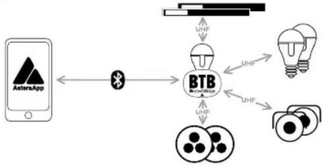
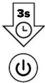
Connect light as BTB
Please note: This ONLY works for Astera lights with built-in Bluetooth.
Please power on the light. Hold down the power button for 3 seconds until the light flashes blue. In the AsteraApp press „Manage Bluetooth Bridges“, then “+” and follow instructions on screen to connect. The light which is connected as BTB shows a small Bluetooth icon in the display. 1. PlutoFresnel 2. Astera
flowchart
graph TD
    A["AstersApp"] <--> B["Bluetooth"]
    B --> C["BTB"]
    C --> D["UHF"]
    C --> E["UHF"]
    C --> F["UHF"]
    C --> G["UHF"]
    C --> H["UHF"]
    C --> I["UHF"]
    C --> J["UHF"]
    C --> K["UHF"]
    C --> L["UHF"]
    C --> M["UHF"]
    C --> N["UHF"]
    C --> O["UHF"]
    C --> P["UHF"]
    C --> Q["UHF"]
    C --> R["UHF"]
    C --> S["UHF"]
    C --> T["UHF"]
    C --> U["UHF"]
    C --> V["UHF"]
    C --> W["UHF"]
    C --> X["UHF"]
    C --> Y["UHF"]
    C --> Z["UHF"]
    C --> AA["UHF"]
    C --> AB["UHF"]
    C --> AC["UHF"]
    C --> AD["UHF"]
    C --> AE["UHF"]
    C --> AF["UHF"]
    C --> AG["UHF"]
    C --> AH["UHF"]
    C --> AI["UHF"]
    C --> AJ["UHF"]
    C --> AK["UHF"]
    C --> AL["UHF"]
    C --> AM["UHF"]
    C --> AN["UHF"]
    C --> AO["UHF"]
    C --> AP["UHF"]
    C --> AQ["UHF"]
    C --> AR["UHF"]
    C --> AS["UHF"]
    C --> AT["UHF"]
    C --> AU["UHF"]
    C --> AV["UHF"]
    C --> AW["UHF"]
    C --> AX["UHF"]
    C --> AY["UHF"]
    C --> AZ["UHF"]
    C --> BA["UHF"]
    C --> BB["UHF"]
    C --> BC["UHF"]
    C --> BD["UHF"]
    C --> BE["UHF"]
    C --> BF["UHF"]
    C --> BG["UHF"]
    C --> BH["UHF"]
    C --> BI["UHF"]
    C --> BJ["UHF"]
    C --> BK["UHF"]
    C --> BL["UHF"]
    C --> BM["UHF"]
    C --> BN["UHF"]
    C --> BO["UHF"]
    C --> BP["UHF"]
    C --> BQ["UHF"]
    C --> BR["UHF"]
    C --> BS["UHF"]
    C --> BT["UHF"]
    C --> BU["UHF"]
    C --> BV["UHF"]
    C --> BW["UHF"]
    C --> BX["UHF"]
    C --> BY["UHF"]
    C --> BZ["UHF"]
    C --> CA["UHF"]
    C --> CBU["UHF"]
    C --> CCU["UHF"]
    C --> CDU["UHF"]
    C --> CEU["UHF"]
    C --> CFU["UHF"]
    C --> CGU["UHF"]
    C --> CHU["UHF"]
    C --> CIU["UHF"]
    C --> CJU["UHF"]
    C --> CKU["UHF"]
- PlutoFresnel
- AsteraApp
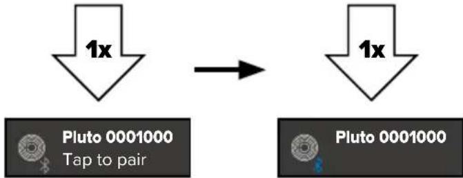
flowchart
graph LR
    A["1x"] --> B["Pluto 0001000 Tap to pair"]
    B --> C["1x"]
- AsteraApp
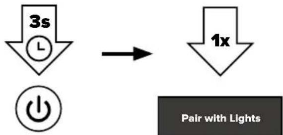
6. Pair with lights
Once the AsteraApp is connected to a BluetoothBridge, you can pair your lights with the app:
Please power on the light(s). Then hold down the power button for 3 seconds until the lights flash blue. Go to “Pair with Lights” dialog in the AsteraApp. Then press OK.
- PlutoFresnel
flowchart
graph LR
    A["3s"] --> B["1x"]
    C["Power"] --> D["Pair with Lights"]
- AsteraApp
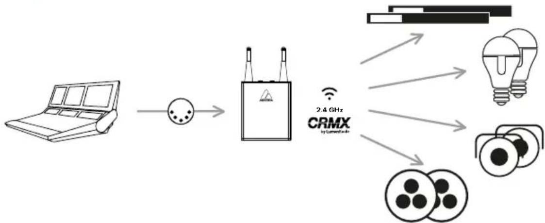
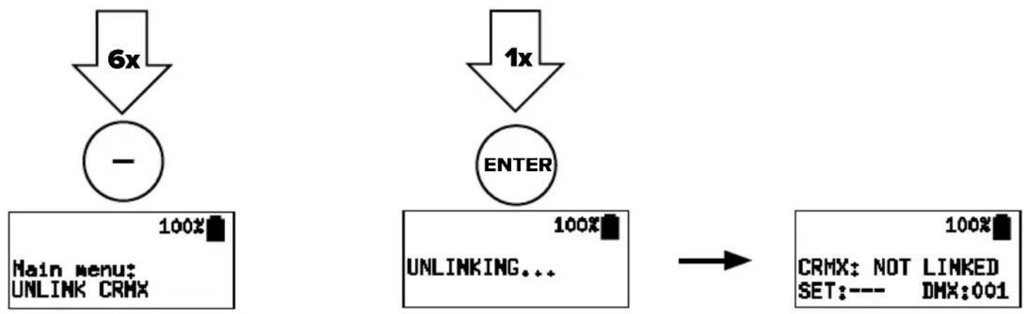
7. Linking to a CRMX transmitter
The PlutoFresnel can be controlled via Wireless DMX/ CRMX. To do this, it must first be connected to a CRMX transmitter. There are two different methods to do this: either the connection is established by pressing a button on the transmitter or a linking key is set that matches the transmitter.
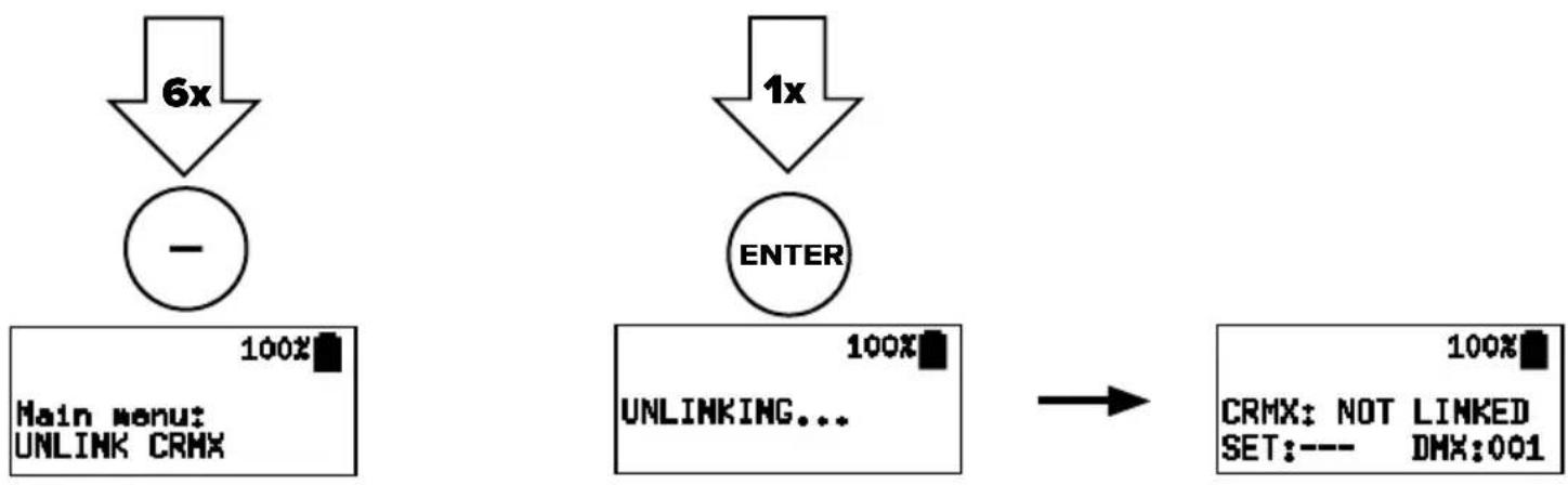
Linking via push button
flowchart
graph LR
    A["Laptop"] --> B["Amplifier"]
    B --> C["CRMX Device"]
    C --> D["2.4 GHz CRMX by Connected Web"]
    C --> E["Light Bulb"]
    C --> F["Film reels"]
- PlutoFresnel 3. PlutoFresnel
- PlutoFresnel
flowchart
graph TD
    A["6x"] --> B["Main menu: UNLINK CRMX"]
    C["1x"] --> D["ENTER"]
    B --> E["100%"]
    D --> F["100%"]
    G["CRMX: NOT LINKED SET:--- DMX:001"] --> H["→"]
- PlutoFresnel4. Aste
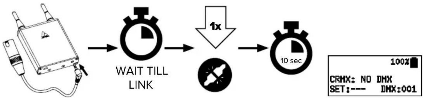
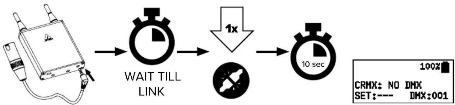
flowchart
graph LR
    A["Measurement Device"] --> B["WAIT TILL LINK"]
    B --> C["1x Speed Drop"]
    C --> D["10 sec"]
    D --> E["Output: 100% CRMX: NO DMX, SET:--- DMX:001"]
Linking via linking key
Alternatively, PlutoFresnel can also be connected to a CRMX transmitter using a linking key, provided that the transmitter supports this linking option. To set a linking key, navigate in the main menu to „DMX SETTINGS“. Under „CRMX LINK BY KEY“ you can enter the desired eight-digit combination.
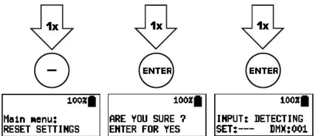
8. Reset
RESET sets „Input Select“ to „AUTO“ and runtime to 5 h.
9. Charging
While the power cable is connected, the display shows the charging status. Charge immediately when the battery is empty. Do not store the unit when the battery is empty.
10. Rigging
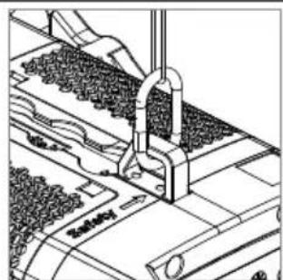
The PlutoFresnel is equipped with Airline-Tracks on all four sides to attach various Astera mounting accessories. When installing accessories on the airline tracks, they must audibly click into place!
natural_image
Technical line drawings of two mechanical components with no visible text or symbols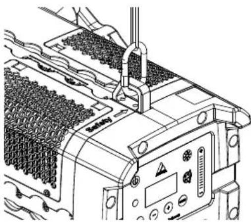
natural_image
Technical line drawing of a mechanical assembly with no visible text or symbolsWith the included multi-functional yoke, PlutoFresnel can be easily hung or placed on the floor. When hanging, always secure with a safety wire at the safety eyelet on top of the light's housing. Make sure the light cannot drop more than 20cm if primary mounting fails.
The PlutoFresnel can also be mounted on tripods. For this purpose, a TVMP (TV to motion picture) adapter that can be attached to the yoke of the PlutoFresnel is included with the product.
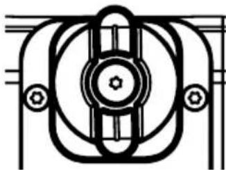
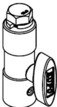
Yoke (AF80-YK) attachment with YokeBase (AF80-YKB) - Quick Release
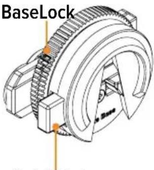
Quick Release
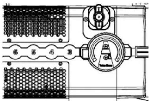
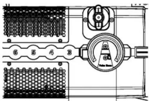
To attach the PlutoFresnel yoke, the two YokeBases must first be inserted into the AirlineTracks on opposite sides. To secure the YokeBase, turn the BaseLock clockwise.
The scales in the AirlineTracks help to ensure that the same position is selected on both sides. There is a default position for the YokeBase.
natural_image
Mechanical assembly diagram showing gear and housing components (no text or labels)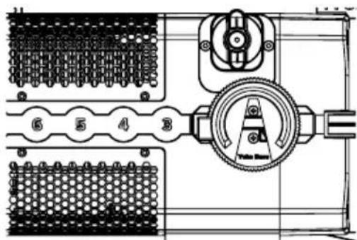
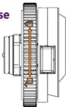
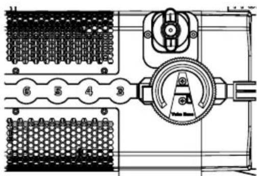
You can move the YokeBase to balance the light or to use it in a different configuration. It is important that the YokeBase is oriented so that the opening of the V points downward. When the light is properly prepared, the yoke can be inserted into the YokeBases from the bottom up.
The yoke is attached to the YokeBases with a Quick Release system. To release the yoke, first loosen the Tilt Lock. This acts as a safety for the Quick Release. Once the Tilt Lock is loose, press the QuickRelease buttons on each YokeBase to release the fixture from the Yoke. Make sure to hold the fixture securely while releasing it.
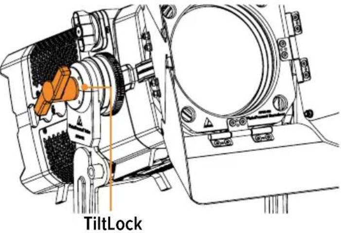

Attention: Only unscrew YokeBase if yoke is detached!
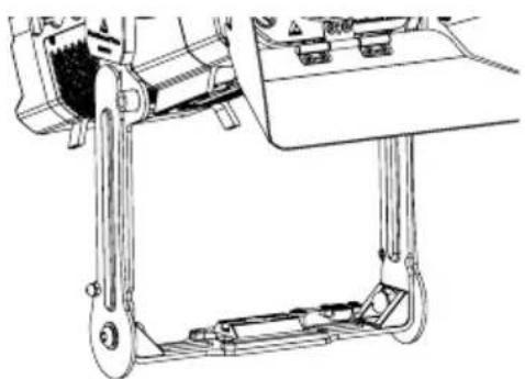
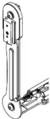
Yoke as floor stand
The PlutoFresnel yoke can be used to floor mount the light. To do this, the two legs are folded out.
natural_image
Technical line drawing of a mechanical assembly with levers and gears (no text or symbols)
natural_image
Technical line drawing of a mechanical assembly with levers and brackets (no text or symbols)Mounting options with Yoke (AF80-YK)
natural_image
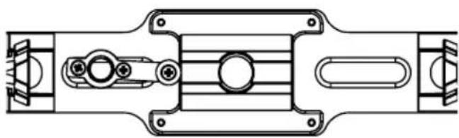
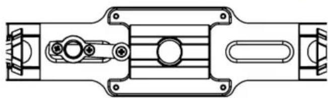
Technical line drawing of a mechanical assembly with no visible text or symbolsThe PlutoFresnel Yoke has a mounting hole allowing for the use of up to 1/2" or M12 bolt, as well as being able to be converted to a 3/8" thread to attach spigots or bolts to the yoke. The 3/8" thread adapter is mounted to the inside of the yoke and swings in place. There is also an AirlineTrack for use with TrackPin and similar.
natural_image
Technical line drawing of a mechanical linkage assembly (no text or symbols)On the left outside is a BrickMount (PB15-BMO), to which suitable Astera accessories, such as a RuntimeExtender can be attached.
TVMP Adapter (AX-TVMP)
natural_image
Technical line drawing of a mechanical component with no visible text or symbolsThe TVMP adapter has a 1/2" thread on top and comes with a 1/2" bolt with washer. With this bolt the TVMP adapter can be attached to the hole of the PlutoFresnel yoke.
This allows the PlutoFresnel to be mounted on stands using the BabyPin (5/8") receiver or the JuniorPin (1-1/8").

In this application, the TVMP T-Bolt can be stowed on a dedicated thread on the yoke to prevent it from being lost.
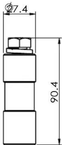
TrackHandle (AX-THD)
The included TrackHandle easily converts the PlutoFresnel into a handheld light. To do this, simply attach the TrackHandle with its robust double stud fitting to one of the PlutoFresnel's AirlineTracks.
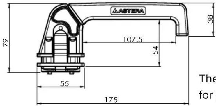
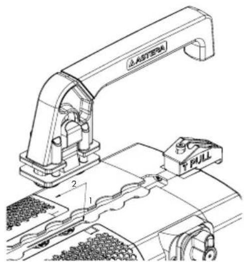
The TrackHandle is also a useful accessory for general handling of the light.
11. Beam modifiers
PlutoFresnel can not only be used as Fresnel but also be used as an open face light without any beam modifiers. In addition to the Fresnel lens, Barndoors are included in the product scope.
Fresnel Lens (AF80-FL)
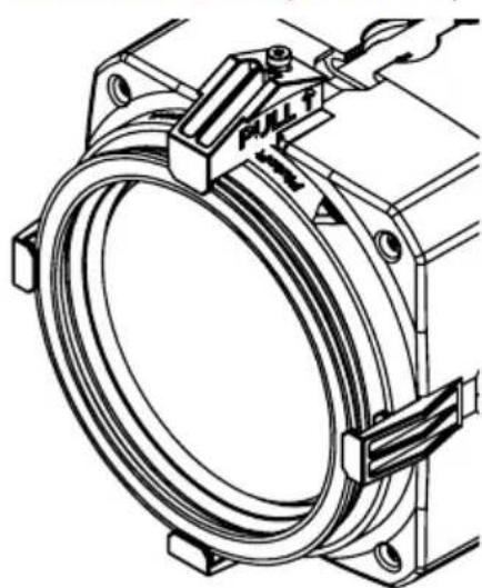
natural_image
Technical line drawing of a mechanical assembly with a coiled spring and fastener (no text or symbols)With the included Fresnel lens PlutoFresnel provides a beam from 15^ to 60^ .
To insert the Fresnel lens, pull the barndoor lock upwards (1) and turn it to the side (2). Now slide the Fresnel lens into the holder (3) and close the barndoor lock by lifting and turning it again (5). Make sure that the barndoor lock is properly engaged before moving the light.

Barndoor (AF80-BD)
8 leaf barndoor is included as standard. They are inserted in front of the Fresnel lens in the same way as the Fresnel lens (4).
Zoom
The built-in zoom allows adjustment of the beam between 15^ and 60^ . There is a scale on the side of the lens tube for reference.
natural_image
Pure mechanical diagram of a symmetrical mechanical component with no text or symbolsTROUBLESHOOTING
| Problem Possible cause Solution | ||
| The fixture does not turn on. The battery may be empty. Connect it to power and try again. | ||
| The fixture turns on and the display is on, but the LEDs do not emit light. | The fixture could be set to BLACKOUT mode. Set to display black color or is operating in DMX mode and doesn’t receive a valid signal. | It is good practice to do a RESET SETTINGS. |
| The fixture is not working correctly - it does not display the color or effect chosen. | The fixture may still be operating under a previous setting. | It is good practice to do a RESET SETTINGS between setups. |
| The power cable is connected but the fixture is not charging. | The battery may be fully charged. | The fixture will only commence charging when its battery has a temperature of 45°C or less. Turn the fixture off and let it cool down; once cold enough, it will start charging. |
SPECIFICATIONS - TECHNICAL DATA
| Order Code AF80 | |
| LED Engine Titan LED Engine | |
| Colors RGBMintAmber | |
| Total LED Power 105 W | |
| LED Power Draw 80 W | |
| CRI (Ra)/ TLCI 3200- 6500 K* ≥ 96 | |
| Beam Angle 15° - 60° | |
| Strobe 0 - 25 Hertz | |
| Pixels 1 | |
| Battery Runtime Up to 20 hours | |
| Battery Runtime max. Brightness 3h | |
| Battery Lifetime 80 % after 400 cycles | |
| DC Input 24 VDC, 80 W | |
| DC Connector 5.5 mm x 2.1 mm | |
| Power Consumption (max.) | 80 W |
| Wired DMX | Yes via FP3-DTL / PWB-2-86W |
| CRMX Receiver | Built-in |
| BluetoothBridge BTB | Built-in |
| Wireless Protocols | CRMX, UHF, Bluetooth, WiFi |
| Wireless Range | CRMX/UHF up to 300 m / 330 ydsBluetooth up to 3 m / 3.3 yds |
| RDM Support | Wireless |
| Infrared Control Yes | |
| TouchSlider Yes | |
| Housing Material | Polymer & Metal |
| IP Rating unwired | IP55 (only with PB15-PLG) |
| IP Rating wired | IP55 (only with PWB-CAB-0.2/-1.5/-5/-10/-15) |
| Ambient Operating Temperature | 0 - 40 °C / 32 - 104 °F |
| Weight (with AF80-FL, AF80-BD) | 4.637 kg / 10.22 lbs |
| Weight (with AF80-FL, AF80-BD, AF80-YK, 2x AF80-YKB, AF80-THD) | 6.493 kg / 14.31 lbs |
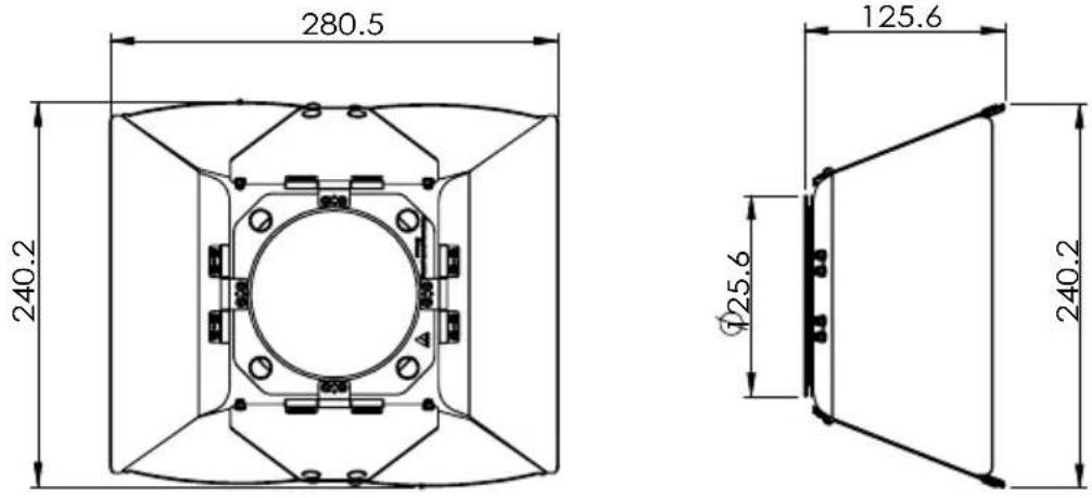
| Dimensions L x W x H | 281.9 mm x 153.5 mm x 161.8 mm / 11.1" x 6.0" x 6.4" |
| Dimensions L x W x H(AF80-YK, 2x AF80-YKB) | 281.9 mm x 244.7 mm x 323 mm / 11.1" x 9.6" x 12.7" |
DISPOSAL
natural_image
Symbol of a trash bin crossed with no text or labels, representing waste sorting or disposal (no text present)- The light contains a lithium ion battery.
- Don't throw the unit into the garbage at the end of its lifetime.
- Make sure to dispose of according to your local ordinances and/or regulations, to avoid polluting the environment!
- The packaging is recyclable and can be disposed.
MANUFACTURERS DECLARATION
Hereby, Astera LED Technology GmbH declares that the type of radio equipment PlutoFresnel complies with Directive 2014/53 / EU. The full text of the EU Declaration of Conformity is available at the following Internet address: https://astera-led.com/plutofresnel.
Astera LED Technology GmbH declares that this equipment has been tested and found to comply with the limits for a Class B digital device, pursuant to part 15 of the FCC rules. These limits are designed to provide reasonable protection against harmful interference in a residential installation. This equipment generates uses and can radiate radio frequency energy and, if not installed and used in accordance with the instructions, may cause harmful interference to radio communications. However, there is no guarantee that interference will not occur in a particular installation. If this equipment does cause harmful interference to radio or television reception, which can be deter-mined by turning the equipment off and on, the user is encouraged to try to correct the interference by one or more of the following measures:
- Reorient or relocate the receiving antenna.
- Increase the separation between the equipment and receiver.
- Connect the equipment into an outlet on a circuit different from that to which the receiver is connected.
- Consult the dealer or an experienced radio/TV technician for help.
FCC Caution:
- Any changes or modifications not expressly approved by the party responsible for compliance could void the user's authority to operate this equipment.
- This transmitter must not be co-located or operating in conjunction with any other antenna or transmitter.
This device complies with Part 15 of the FCC Rules. Operation is subject to the following two conditions:
(1) This device may not cause harmful interference, and
(2) This device must accept any interference received, including interference that may cause undesired operation.
FCC RF Radiation Exposure Statement Caution: To maintain compliance with the FCC's RF exposure guidelines, place the product at least 20 cm from nearby persons.
RF CHARACTERISTICS
| Wireless Modules Modulation | ERP(Transmitter) | Channel Count | |
| EU: UHF***(863-870 MHz) FHSS < 25 mW 47 | |||
| USA: UHF (917-922.20 MHz) FHSS < 25 mW 53 | |||
| AUS: UHF (922.30-927.50 MHz) FHSS < 25 mW 53 | |||
| SGP: UHF (920.50-924.50 MHz) FHSS < 25 mW 41 | |||
| KOR: UHF (917.9-921.5 MHz) FHSS < 25 mW 10 | |||
| RUS: UHF (868.75-869.12 MHz) FHSS < 25 mW 6 | |||
| JPN: UHF (922.80-926.40 MHz) FHSS < 25 mW 19 | |||
| CRMX (2402-2480 MHz) FHSS < 100 mW 79 | |||
| Bluetooth 5.0 LE(2402-2480 MHz) | FHSS | 10 mW (BLE) | 40 |
| WiFi (2412-2472 MHz) | DSSS, OFDM | < 100 mW | 13 |
*** General allocation of frequencies for use by short-range radio applications
Spectrum usage regulations:
| Frequency range in MHz1) | Maximum equivalent radiant power (ERP) | Additional parameters / frequency access and interference mitigation techniques |
| 865 - 868 | 25 mW | Requirements for frequency access and mitigation techniques3) Alternatively, a maximum duty cycle2) of 1% can be used. |
| 868,0 - 868,6 | 25 mW | Requirements for frequency access and mitigation techniques3) Alternatively, a maximum duty cycle2) of 1% can be used. |
| 868,7 - 869,2 | 25 mW | Requirements for frequency access and mitigation techniques3) Alternatively, a maximum duty cycle2) of 0.1% can be used. |
| 869,40 - 869,65 | 500 mW | Requirements for frequency access and mitigation techniques3) Alternatively, a maximum duty cycle2) of 10% can be used. |
| 869,7 - 870,0 | 25 mW | Requirements for frequency access and mitigation techniques3) Alternatively, a maximum duty cycle2) of 1% can be used. |
^1) The use of adjacent frequency bands within this table as a single frequency band is permitted, provided that the specific conditions for each of these adjacent frequency bands are met.
2) „duty cycle“ means the ratio of (T_on)/(T_obs) expressed as a percentage, where T_on is the ,on-time' of a single transmitting device and T_obs is the observation period T_on is measured in an observation frequency band (F_obs) . Unless otherwise specified in this general allocation, T_obs is a continuous period of one hour and F_obs is the applicable frequency band in this general allocation (table).
3) Frequency access and interference mitigation techniques shall be used whose performance level at least meets the essential requirements of Directive 2014/53/EU or the Radio Equipment Act (FuAG). Where relevant techniques are described in harmonized standards, the references of which have been published in the Official Journal of the European Union pursuant to Directive 2014/53/EU, or parts thereof, performance shall be ensured which is at least equivalent to those techniques.
LIEFERUMFANG
natural_image
Technical line drawing of a mechanical assembly with no visible text or symbols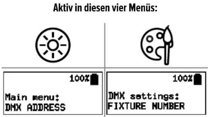
2. Ein-/Ausschalten
flowchart
graph LR
    A["Printer"] --> B["Mouse"]
    B --> C["MCPU"]
    C --> D["2.4 GHz CRMX by Camera"]
    D --> E["Camera with lens"]
    D --> F["Camera with light bulb"]
    D --> G["Camera with film reel"]
- PlutoFresnel 3. PlutoFresnel
flowchart
graph TD
    A["6x"] --> B["Main menu: UNLINK CRMX"]
    C["1x"] --> D["ENTER"]
    B --> E["100%"]
    D --> F["100%"]
    G["CRMX: NOT LINKED SET:--- DHX:001"] --> H["-->"]
-
PlutoFresnel
-
PlutoFresnel4. Aste
flowchart
graph LR
    A["Measurement Device"] --> B["WAIT TILL LINK"]
    B --> C["1x Speed Drop"]
    C --> D["10 sec"]
    D --> E["Output: CRMX: NO DMX, SET: --- DMX:001"]
natural_image
Technical line drawings of two mechanical components with coiled springs and a control panel (no text or symbols)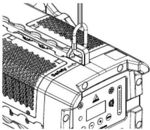
natural_image
Technical line drawing of a mechanical device with clamping mechanism and grid array (no text or symbols)natural_image
Technical diagram of a mechanical assembly with threaded shaft and housing (no text or symbols)natural_image
Technical line drawing of a mechanical assembly with no visible text or symbols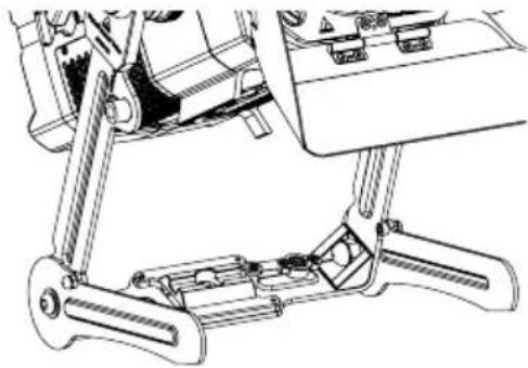
natural_image
Technical line drawing of a mechanical assembly with levers and brackets (no text or symbols)natural_image
Technical line drawing of a mechanical assembly with no visible text or symbolsnatural_image
Technical line drawing of a mechanical linkage assembly (no text or symbols)TVMP-Adapter (AX-TVMP)
natural_image
Technical line drawing of a mechanical component with no visible text or symbols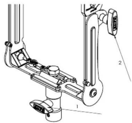
natural_image
Technical line drawing of a mechanical linkage assembly with labeled parts (no text or symbols present)natural_image
Technical line drawing of a mechanical assembly with a coiled spring and attached fastener (no text or symbols)natural_image
Pure mechanical diagram of a symmetrical mechanical component with no text or symbolsFEHLERBEHEBUNG
natural_image
Technical line drawing of a mechanical assembly or installation with pipes and components (no visible text or symbols)
natural_image
Technical line drawings of two mechanical components with internal gear and mounting brackets (no text or symbols)
natural_image
Technical line drawing of a mechanical assembly with no visible text or symbolsnatural_image
Technical line drawing of a mechanical gear assembly (no text or symbols)Sgancio rapido
natural_image
Technical diagram of a mechanical assembly with gears and housing (no text or labels)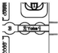
natural_image
Technical line drawing of a mechanical assembly with gears and components (no text or symbols)Blocco inclinazione

natural_image
Technical line drawing of a mechanical assembly with no visible text or symbols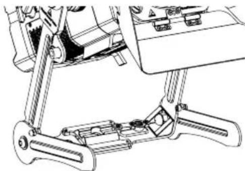
natural_image
Technical line drawing of a mechanical assembly with levers and brackets (no text or symbols)natural_image
Technical line drawing of a mechanical component with symmetrical slots and mounting holes (no text or symbols)natural_image
Technical line drawing of a mechanical linkage assembly (no text or symbols)natural_image
Technical line drawing of a mechanical component with no visible text or symbols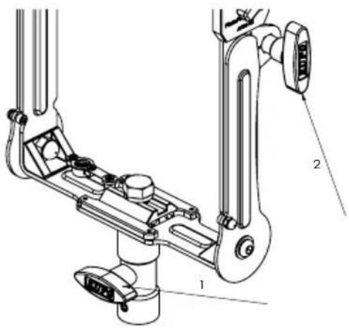
natural_image
Technical line drawing of a mechanical assembly with labeled parts (no text or symbols present)natural_image
Technical line drawing of a mechanical assembly with a coiled spring and mounting bracket (no text or symbols)Paraluce a 8 alette (AF80-BD)
Zoom
natural_image
Pure mechanical diagram of a symmetrical mechanical component with no text or symbolsnatural_image
Isometric architectural or engineering diagram showing a curved pipe system and surrounding terrain (no text or symbols)LIMPIEZA Y MANTENIMIENTO


natural_image
Technical line drawings of two mechanical components with meshed surfaces and mounting brackets (no text or symbols)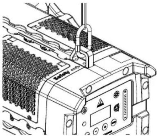
natural_image
Technical line drawing of a mechanical device with clamping mechanism and grid array (no text or symbols)natural_image
Mechanical gear assembly diagram showing shaft, gear teeth, and housing (no text or labels)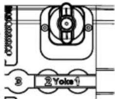
natural_image
Technical line drawing of a mechanical assembly with no visible text or symbols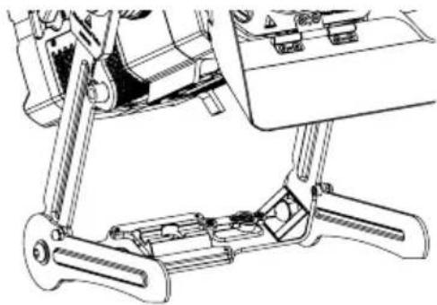
natural_image
Technical line drawing of a mechanical assembly with levers and brackets (no text or symbols)natural_image
Technical line drawing of a mechanical assembly with symmetrical components and mounting holes (no text or symbols)natural_image
Technical line drawing of a mechanical linkage assembly (no text or symbols)natural_image
Technical line drawing of a mechanical component with no visible text or symbols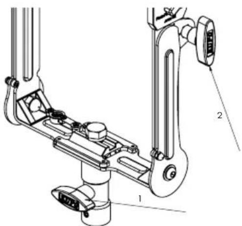
natural_image
Technical line drawing of a mechanical assembly with a coiled spring and pull switch (no text or symbols)Barndoor (AF80-BD)
Zoom
natural_image
Pure mechanical diagram of a symmetrical mechanical component with no text or symbolsnatural_image
Technical line drawing of a mechanical assembly with pipes and components (no text or symbols)NETTOYAGE ET MAINTENANCE

PixelBrick, Titan Tube BTB, Helios Tube BTB.
natural_image
Technical line drawings of two mechanical components with coiled springs and housing (no text or symbols)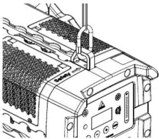
natural_image
Technical line drawing of a mechanical device with multiple ports and control panel (no visible text or symbols)natural_image
Technical diagram of a mechanical gear assembly with no visible text or symbols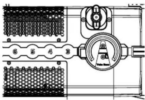

natural_image
Technical line drawing of a mechanical assembly with no visible text or symbols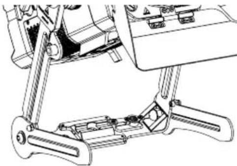
natural_image
Technical line drawing of a mechanical assembly with levers and brackets (no text or symbols)natural_image
Technical line drawing of a mechanical component with symmetrical slots and mounting holes (no text or symbols)natural_image
Technical line drawing of a mechanical linkage assembly (no text or symbols)natural_image
Technical line drawing of a mechanical component with no visible text or symbols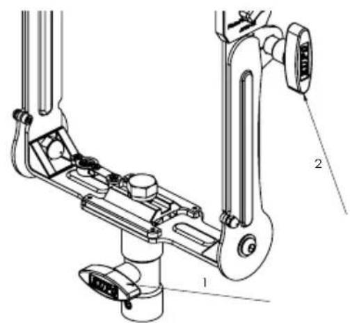
natural_image
Technical line drawing of a mechanical assembly with a coiled spring and mounting bracket (no text or symbols)natural_image
Technical line drawing of a mechanical assembly with no visible text or symbols清洁和维护

natural_image
Technical line drawings of two mechanical components with no visible text or symbols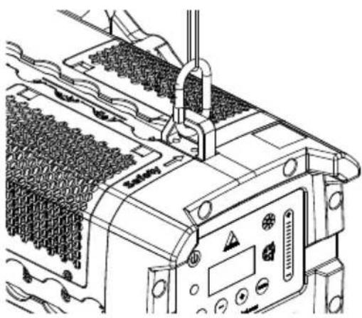
natural_image
Technical line drawing of a mechanical assembly with no visible text or symbolsnatural_image
Technical line drawing of a mechanical gear assembly (no text or symbols)natural_image
Technical diagram of a mechanical gear assembly with no visible text or symbols快速释放装置
natural_image
Technical line drawing of a mechanical assembly with levers and components (no text or symbols)
natural_image
Technical line drawing of a mechanical assembly with levers and brackets (no text or symbols)Yo ke 的安装选项 (AF80-YK)
natural_image
Technical line drawing of a mechanical component with symmetrical features and mounting holes (no text or symbols)natural_image
Technical line drawing of a mechanical linkage assembly (no text or symbols)natural_image
Technical line drawing of a mechanical component with no visible text or symbols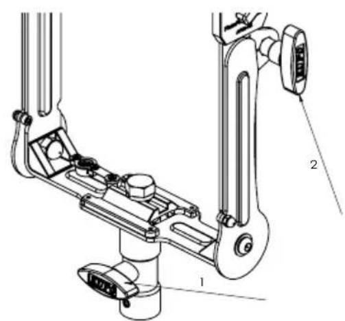
natural_image
Technical line drawing of a mechanical assembly with a coiled spring and mounting bracket (no text or symbols)挡光板 (AF80-BD)
变焦
natural_image
Pure mechanical diagram of a symmetrical mechanical component with no text or symbols故障排除
natural_image
Symbol of a trash bin crossed with no text or numbers, representing waste sorting or disposal (no text present)natural_image
Abstract logo design featuring two overlapping triangles, one purple and one orange, with the word ASTERA below (no additional text or symbols)Contact
Astera LED Technology GmbH
Schatzbogen 60
81829 Munich
Germany
E-mail: info@astera-led.com
Website: www.astera-led.com