AK6500CBS - Basket Zephyr - Free user manual and instructions
Find the device manual for free AK6500CBS Zephyr in PDF.

User questions about AK6500CBS Zephyr
0 question about this device. Answer the ones you know or ask your own.
Ask a new question about this device
Download the instructions for your Basket in PDF format for free! Find your manual AK6500CBS - Zephyr and take your electronic device back in hand. On this page are published all the documents necessary for the use of your device. AK6500CBS by Zephyr.
USER MANUAL AK6500CBS Zephyr
natural_image
Technical line drawing of a mechanical housing component with mounting holes and a central circular recess (no text or symbols)Hurricane
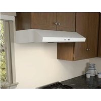
AK2500CS, B, W
AK2536CS, B, W
ACT office Central Technology
natural_image
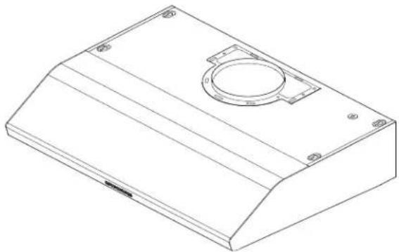
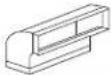
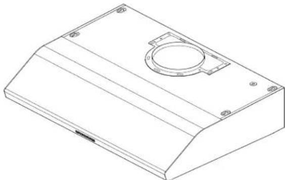
Isometric line drawing of a rectangular electronic enclosure with a circular recess and mounting holes (no text or symbols)Cyclone
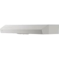
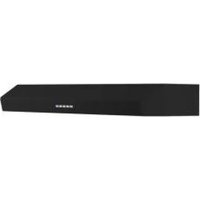
AK6500CS, B, BS, W
AK6536CS, B, BS, W
AK6542CS
natural_image
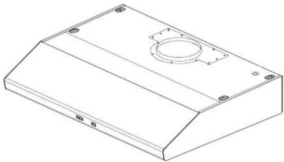
Isometric line drawing of a rectangular metal enclosure with a circular recess and mounting holes (no text or symbols)EN Use, Care, and Installation Guide
Page Safety Information 4-6
Types of Safety Warnings 4
General Safety 4-5
Operation 6
Electrical Requirements 6
List of Materials 7
Installation Instructions 8-20
Ducting Calculation Sheet 8
Mounting Height, Clearance, & Ducting 9-10
Ducting Options ....11
AK21 Hood Specifications ....12
AK25 Hood Specifications ....13
AK65 Hood Specifications ....14
Electrical Supply 15
Cable Lock 15
Rectangular Vertical Ducting Preparation ....16
Rectangular Horizontal Ducting Preparation 17-18
Mounting the Hood 19-20
Features & Controls 21-23
AK21 Capacitive Touch ....21
AK25 Electronic Touch 22
AK65 Mechanical Slide 23
Maintenance 24-27
Hood & Filter Cleaning 24-26
LumiLight LED 27
ACT™ Conversion 28-30
Airflow Control Technology (ACT™) 28
Enabling ACT™ 29-30
Wiring Diagram 31
Troubleshooting.... 32
List of Parts & Accessories 33
Notes....34
Limited Warranty 35
Product Registration....36
READ AND SAVE THESE INSTRUCTIONS
Your safety and the safety of others are very important.
We have provided many important safety messages in this manual for your appliance. Always read and obey all safety messages.

This is the Safety Alert Symbol. This symbol alerts you to potential hazards that can cause severe bodily injury or death. All safety messages will follow the Safety Alert Symbol and either the words "DANGER" "WARNING" or "CAUTION"

DANGER

Danger means that failure to heed this safety statement may result in severe injury or death.

WARNING

Warning means that failure to heed this safety statement may result in extensive product damage, serious personal injury, or death.

CAUTION

Caution means that failure to heed this safety statement may result in minor or moderate personal injury, property or equipment damage.
General Safety

WARNING

To reduce the risk of fire or electric shock, do not use this fan with any solid-state control device.

WARNING

WARNING - TO REDUCE THE RISK OF FIRE, ELECTRIC SHOCK, OR INJURY TO PERSONS, OBSERVE THE FOLLOWING:
a) Use this unit only in the manner intended by the manufacturer. If you have questions, contact the manufacturer.
b) Before servicing or cleaning unit, switch power off at service panel and lock the service disconnecting means to prevent power from being switched on accidentally. When the service disconnecting means cannot be locked, securely fasten a prominent warning device, such as a tag, to the service panel.

CAUTION

For General Ventilating Use Only. Do Not Use To Exhaust Hazardous Or Explosive Materials And Vapors. Take care when using cleaning agents or detergents. Suitable for use in household cooking area.

WARNING

WARNING - TO REDUCE THE RISK OF A RANGE TOP GREASE FIRE:
a) Never leave surface units unattended at high settings. Boilovers cause smoking and greasy spillovers that may ignite. Heat oils slowly on low or medium settings.
b) Always turn hood ON when cooking at high heat or when flambeing food. (i.e. Crepes Suzette, Cherries Jubilee, Peppercorn Beef Flambe').
c) Clean ventilating fans frequently. Grease should not be allowed to accumulate on fan or filter.
d) Use proper pan size. Always use cookware appropriate for the size of the surface element.
READ AND SAVE THESE INSTRUCTIONS

WARNING

WARNING - TO REDUCE THE RISK OF INJURY TO PERSONS IN THE EVENT OF A RANGE TOP GREASE FIRE, OBSERVE THE FOLLOWING ^a :
a) SMOTHER FLAMES with a close-fitting lid, cookie sheet, or metal tray, then turn off the burner. BE CAREFUL TO PREVENT BURNS. If the flames do not go out immediately, EVACUATE AND CALL THE FIRE DEPARTMENT.
b) NEVER PICK UP A FLAMING PAN – You may be burned.
c) DO NOT USE WATER, including wet dishcloths or towels – a violent steam explosion will result.
d) Use an extinguisher ONLY if:
1) You know you have a Class ABC extinguisher, and you already know how to operate it.
2) The fire is small and contained in the area where it started.
3) The fire department is being called.
4) You can fight the fire with your back to an exit
°Based on "Kitchen Firesafety Tips" published by NFPA.

WARNING

WARNING
TO REDUCE THE RISK OF FIRE, USE ONLY METAL DUCTWORK.

CAUTION

To reduce risk of fire and to properly exhaust air outside, do not vent exhaust air into spaces within walls, ceilings, attics, crawl spaces, or garages.

WARNING

WARNING - TO REDUCE THE RISK OF FIRE, ELECTRIC SHOCK, OR INJURY TO PERSONS, OBSERVE THE FOLLOWING:
a) Installation work and electrical wiring must be done by qualified person(s) in accordance with all applicable codes and standards, including fire-rated construction.
b) Sufficient air is needed for proper combustion and exhausting of gases through the flue (chimney) of fuel burning equipment to prevent back drafting. Follow the heating equipment manufacturer's guideline and safety standards such as those published by the National Fire Protection Association (NFPA), and the American Society for Heating, Refrigeration and Air Conditioning Engineers (ASHRAE), and the local code authorities.
c) When cutting or drilling into wall or ceiling, do not damage electrical wiring and other hidden utilities.
d) Ducted fans must always be vented to the outdoors.
e) If this unit is to be installed over a tub or shower, it must be marked as appropriate for the application and be connected to a GFCI (Ground Fault Circuit Interrupter) - protected branch circuit.

WARNING

Prop. 65 Warning for California Residents: This product may contain chemicals known to the State of California to cause cancer, birth defects, or other reproductive harm.
READ AND SAVE THESE INSTRUCTIONS
Operation
▶ Always leave safety grilles and filters in place. Without these components, operating blowers could catch onto hair, fingers and loose clothing.
The manufacturer declines all responsibility in the event of failure to observe the instructions given here for installation, maintenance and suitable use of the product. The manufacturer further declines all responsibility for injury due to negligence and the warranty of the unit automatically expires due to improper maintenance.
NOTE: Please check www.zephyronline.com for revisions before doing any custom work.
Electrical Requirements
Important:
▶ Observe all governing codes and ordinances.
It is the customer's responsibility to be aware of these below:
▶ To contact a qualified electrical installer.
To assure that the electrical installation is adequate and in conformance with National Electrical Code, ANSI/NFPA 70 latest edition* or CSA standards C22.1-94, Canadian Electrical Code, Part 1 and C22.2 No.0-M91 - latest edition** and all local codes and ordinances.
If codes permit and a separate ground wire is used, it is recommended that a qualified electrician determine that the ground path is adequate.
▶ Do not ground to a gas pipe.
▶ Check with a qualified electrician if you are not sure the range hood is properly grounded.
▶ Do not have a fuse in the neutral or ground circuit.
This appliance requires a 120V 60Hz electrical supply and connected to an individual properly grounded branch circuit protected by a 15 or 20 ampere circuit breaker or time delay fuse. Wiring must be 2 wire with ground. Please also refer to Electrical Diagram on product.
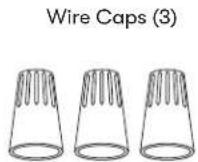
▶ A cable locking connector (not supplied) might also be required by local codes. Check with local requirements, purchase and install appropriate connector if necessary.
* National Fire Protection Association Batterymarch Park, Quincy, Massachusetts 02269
** CSA International 8501 East Pleasant Valley Road, Cleveland, Ohio 44131-5575
Parts Supplied
| Quantity Part | |
| 1 | H |
| 2 Safety grilles | |
| 2 LumiLight LED | |
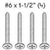
| 1 Hardware package |
7" Round transition adapter (AK21, AK25) 6" Round transition adapter (AK65) (pre-installed on top of hood)
3-1/4"x10" rectangular starting collar
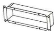
3-1/4"x10" rectangular cover plate (pre-installed on back of hood)
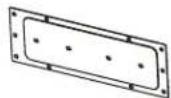
3-1/4"x10" rectangular vertical transition adapter
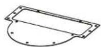
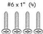
Safety Grille Screws (2)

Parts Not Supplied
| Ducting, conduit and all installation tools |
| Backdraft damper |
| Philips head screwdriver with minimum 8” long shaft (required to install AK2100) |
| Cable locking connector (if required by local codes) |
Ducting Calculation Sheet
| Duct pieces | Equivalent number length x used = | Total | |
 | 3-1/4"x 10" Rect., straight | 1 Ft. x( ) = | Ft. |
 | 6",7",8",10" Round, straight | 1 Ft. x( ) = | Ft. |
 | 3-1/4"x 10" Rect.90° elbow | 15 Ft. x( ) = | Ft. |
 | 3-1/4"x 10" Rect.45° elbow | 9 Ft. x( ) = | Ft. |
 | 3-1/4"x 10" Rect.90° flat elbow | 24 Ft. x( ) = | Ft. |
 | 7" to 6" or 8" to 7" Round tapered reducer | 25 Ft. x( ) = | Ft. |
 | 6",7",8" Round in-line damper | 15 Ft. x( ) = | Ft. |
 | 6",7",8",10" Round, 90° elbow | 15 Ft. x( ) = | Ft. |
 | 6",7",8",10" Round, 45° elbow | 9 Ft. x( ) = | Ft. |
| Subtotal column 1 = | Ft. | ||
Maximum Duct Length: For satisfactory air movement, the total duct length should not exceed 150 equivalent feet.
| Duct pieces | Equivalent number length x used = | Total | |
 | 3-1/4"x 10"Rect. to6" round transition | 5 Ft. x( ) = | Ft. |
 | 3-1/4"x 10"Rect. to6" round transition90° elbow | 20 Ft. x( ) = | Ft. |
 | 6" round to3-1/4"x 10"rect.transition | 1 Ft. x( ) = | Ft. |
 | 6" round to3-1/4"x 10"rect.transition90° elbow | 16 Ft. x( ) = | Ft. |
 | 7" round to3 1/4" x 10"rect.transition | 8 Ft. x( ) = | Ft. |
 | 7" round to3-1/4" x 10"rect.transition90° elbow | 23 Ft. x( ) = | Ft. |
 | 3-1/4"x 10"Rect.wall capwith damper | 30 Ft. x( ) = | Ft. |
 | 6",7",8",10"Round, wallcap withdamper | 30 Ft. x( ) = | Ft. |
 | 6",7",8",10"Roundroof cap | 30 Ft. x( ) = | Ft. |
| Subtotal column 2 =Subtotal column 1 =Total ductwork = | Ft. | ||
| Ft. | |||
| Ft. | |||
Mounting Height, Clearance, & Ducting
text_image
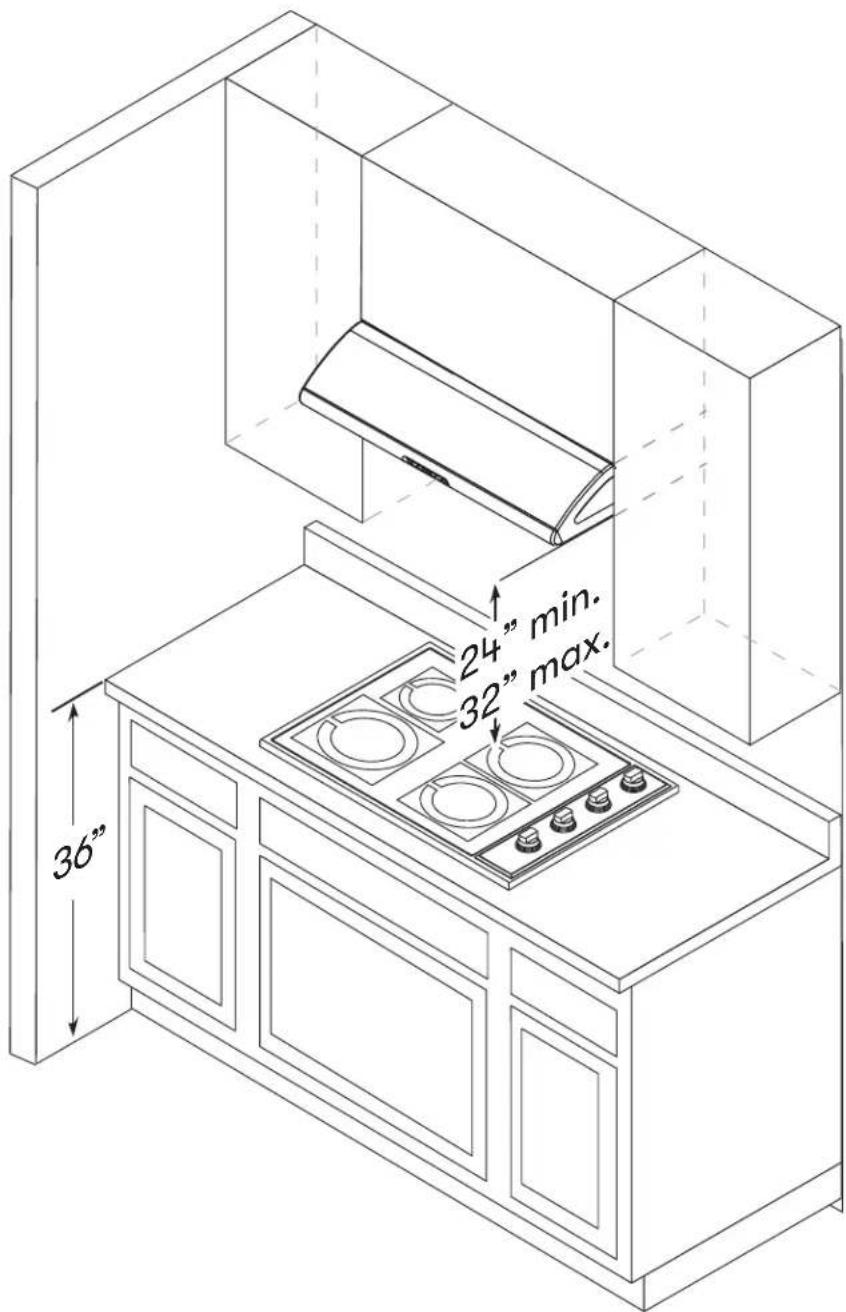
24" min. 32" max. 36"Mounting Height, Clearance, & Ducting
A minimum of 6" round for AK65 and 7" round for AK21 and AK25 or 3-1/4" x 10" rectangular duct must be used to maintain maximum air flow efficiency for vertical ducting. For horizontal ducting, 3-1/4" x 10" rectangular duct is the minimum size.
Always use rigid type metal ducts only. Flexible ducts could restrict air flow by up to 50%.
Use calculation worksheet to compute total available duct run when using elbows, transitions, and caps.
ALWAYS, when possible, reduce the number or transitions and turns. If long duct run is required, increase duct size from 6" to 7" or 7" to 8".
If turns or transitions are required: Install as far away from duct opening and as far apart between the two transitions as possible.
Minimum mount height between range top to hood bottom should be no less than 24".
Maximum mount height should be no higher than 32".
It is important to install the hood at the proper mounting height. Hoods mounted too low could result in heat damage and fire hazard; while hoods mounted too high will be hard to reach and will lose performance and efficiency.
If available, also refer to range manufacturer's height clearance requirements and recommended hood mounting height above range. Always check your local codes for any differences.
For shipment and installation damages:
▶ Please fully inspect unit for damage before installation.
If the unit is damaged in shipment, return the unit to the store in which it was bought for repair or replacement.
If the unit is damaged by the customer, repair or replacement is the responsibility of the customer.
If the unit is damaged by the installer (if other than the customer), repair of replacement must be made by arrangement between customer and installer.
Ducting Options

WARNING

Fire Hazard: NEVER exhaust air or terminate ductwork into spaces between walls, crawl spaces, ceilings, attics, or garages. All exhaust must be ducted to the outside, unless using the recirculating option.
▶ Use single wall rigid metal ductwork only.
▶ Fasten all connections with sheet metal screws and tape all joints w/ certified Silver Tape or Duct Tape.

text_image
cabinet side wall cap w/gravity damper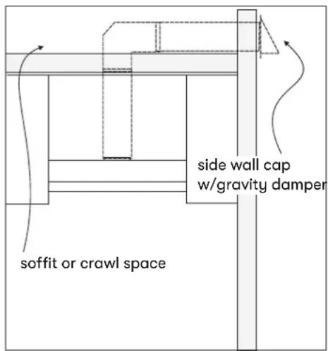
text_image
side wall cap w/gravity damper soffit or crawl space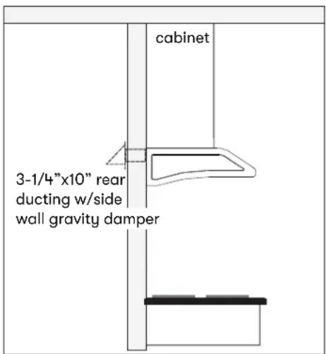
text_image
cabinet 3-1/4"x10" rear ducting w/side wall gravity damper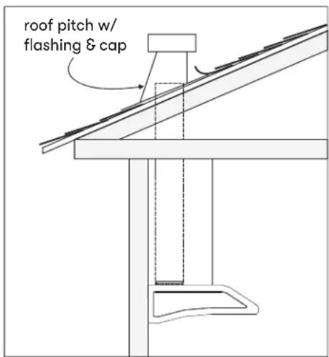
text_image
roof pitch w/ flashing & capAK21 Hood Specifications
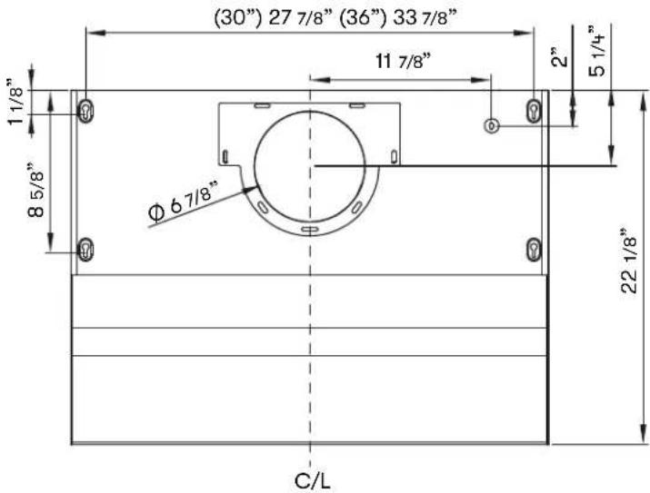
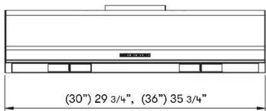
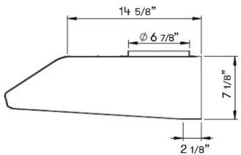
AK25 Hood Specifications
text_image
(30") 27 7/8" (36") 33 7/8" 11 7/8" 2" 5 1/4" Φ6 7/8" 8 5/8" 22 1/8" C/LTOP
text_image
(30") 29 3/4", (36") 35 3/4"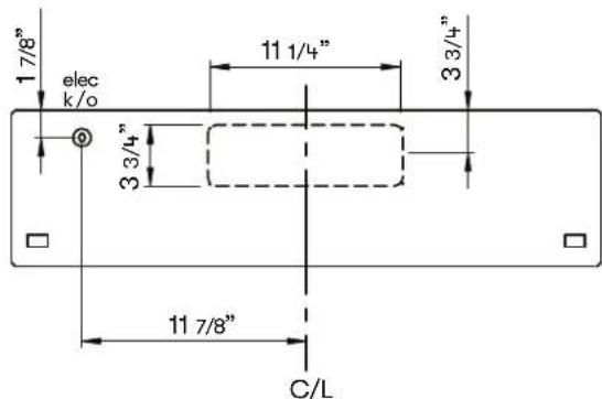
text_image
1 7/8" elec k/o 11 1/4" 3 3/4" 3 3/4" 11 7/8" C/LFRONT BACK
text_image
14 5/8" Ø 6 7/8" 7 1/8" 2 1/8"SIDE
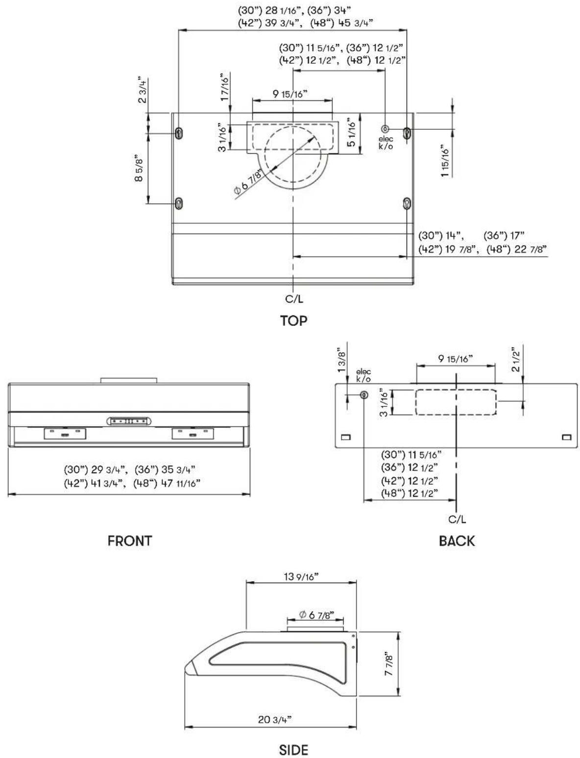
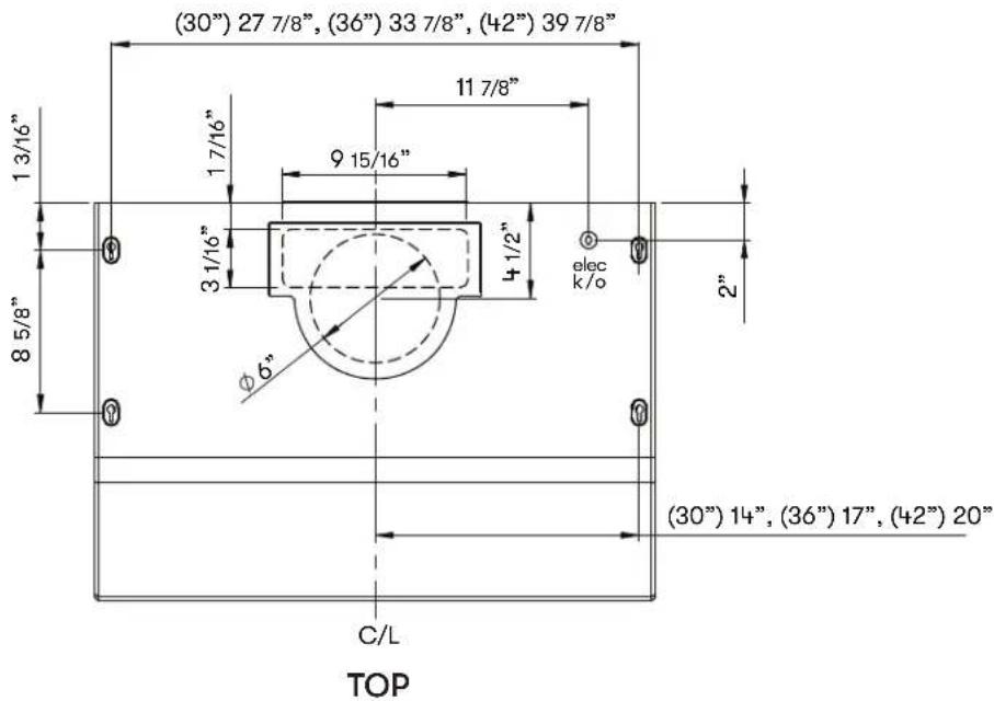
AK65 Hood Specifications
text_image
(30") 27 7/8", (36") 33 7/8", (42") 39 7/8" 1 3/16" 1 7/16" 9 15/16" 3 1/16" 4 1/2" elec k/o 2" 8 5/8" Ø6" (30") 14", (36") 17", (42") 20" C/L TOP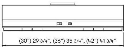
text_image
(30") 29 3/4", (36") 35 3/4", (42") 41 3/4"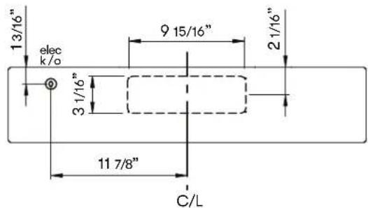
text_image
13/16" elec k/o 9 15/16" 21/16" 3 1/16" 11 7/8" C/LBACK
FRONT
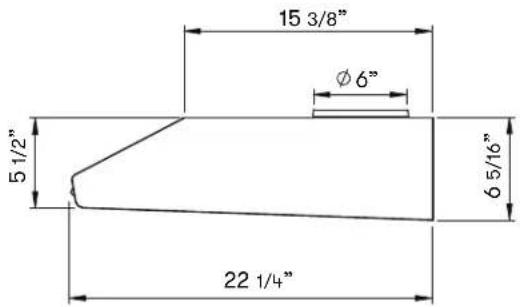
text_image
15 3/8" Ø6" 5 1/2" 6 5/16" 22 1/4"SIDE
Electrical Supply

WARNING

Electrical wiring must be done by qualified person(s) in accordance with all applicable codes and standards. Turn off electrical power at service entrance before wiring.
For personal safety, remove house fuse or open circuit breaker before beginning installation. Do not use extension cord or adapter plug with this appliance.
Follow national electrical codes or prevailing local codes and ordinances.
This appliance requires a 120V 60Hz electrical supply, and connected to an individual, properly grounded branch circuit, protected by a 15 or 20 ampere circuit breaker or time delay fuse. Wiring must be 2 wire w/ ground. Please also refer Electrical Diagram labeled on product.
Cable Lock
A cable locking connector (not supplied) might be required by local codes. Check with local requirements and codes, purchase and install appropriate connector if necessary. (FIG. A)
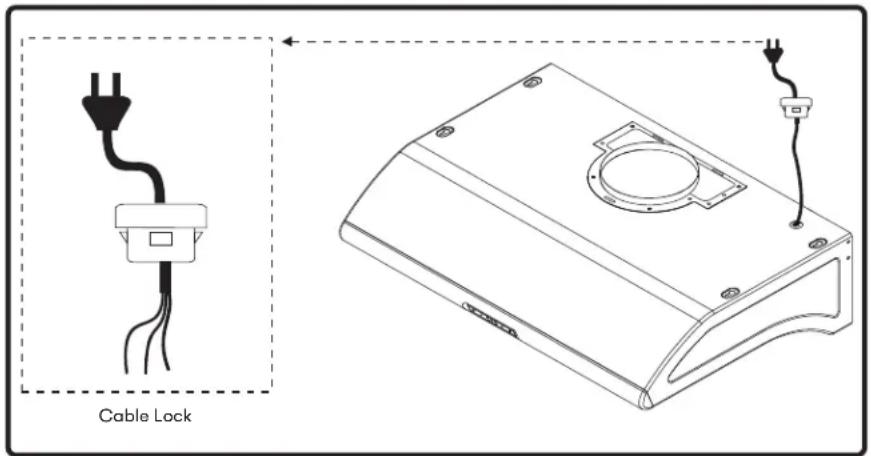
text_image
Cable LockFIG. A
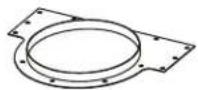
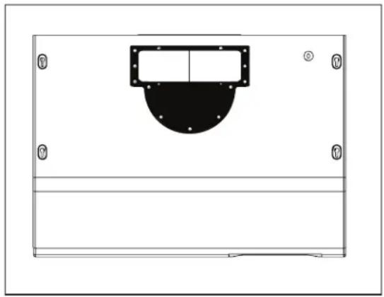
Rectangular Vertical Ducting Preparation
By default the Typhoon and Hurricane are pre-configured for 7" round vertical ducting.
By default the Cyclone is pre-configured for 6" round vertical ducting.
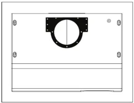
natural_image
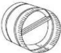
Technical diagram of a mechanical component with mounting holes and a central circular feature (no text or symbols)- Using a Philips-head screwdriver remove the screws and round vertical transition adapter from top of hood body.
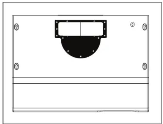
natural_image
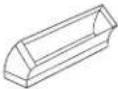
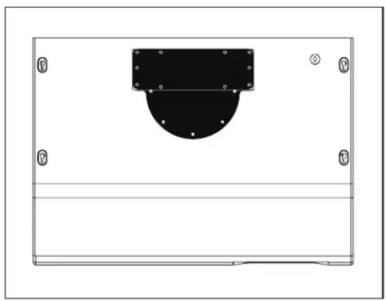
Pure technical diagram of a mechanical component with mounting holes and a central semicircular feature (no text or symbols)- Replace round vertical transition adapter with rectangular transition adapter. Do not secure to hood body yet.
natural_image
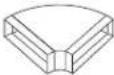
Technical line drawing of a mechanical component with mounting holes and a central circular feature (no text or symbols)- Place 3-1/4"x10" rectangular collar on top of rectangular transition adapter. Secure rectangular adapter and rectangular collar to hood body using the previously removed screws from step 1.
Rectangular Horizontal Ducting Preparation
By default the Typhoon and Hurricane are pre-configured for 7" round vertical ducting.
By default the Cyclone is pre-configured for 6" round vertical ducting.
natural_image
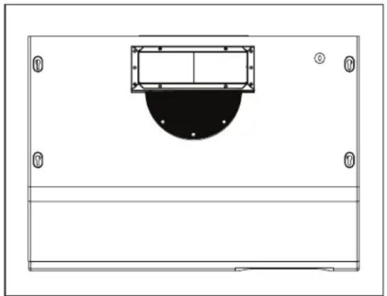
Technical drawing of a mechanical component with mounting holes and a central circular feature (no text or symbols)- Using a Philips-head screwdriver remove the screws and round vertical transition adapter from the top of the hood.
natural_image
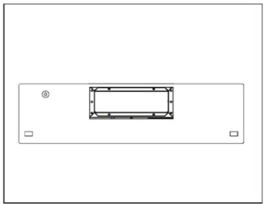
Simple diagram of a rectangular panel with a central black rectangle and four corner markers (no text or symbols)- Using a Philips-head screwdriver, remove the screws and 3-1/4"x10" rectangular cover plate from back of hood.
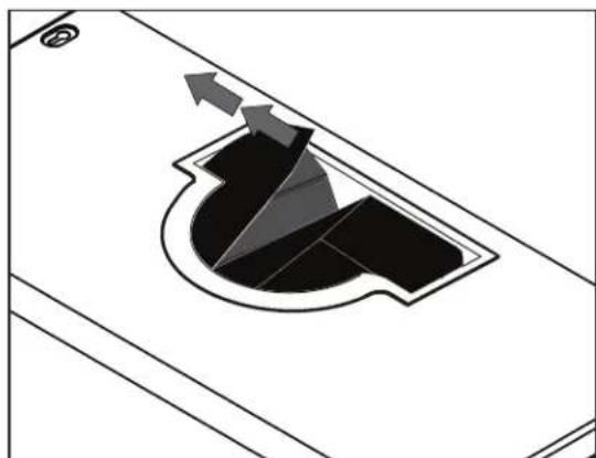
natural_image
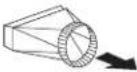
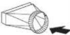
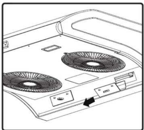
Diagram of a mechanical component with arrows indicating direction (no text or symbols)- Typhoon ONLY. Remove the two plastic air diverter blocks. The blocks are located in the hood and can be accessed from the top when the round transition adapter is removed.
natural_image
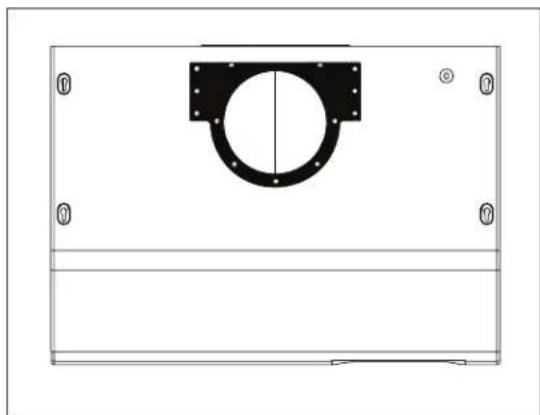
Pure technical diagram of a mechanical component with mounting holes and a central curved section (no text or symbols)- Replace round vertical transition adapter with rectangular transition adapter. Do not secure to hood body yet.
natural_image
Pure technical diagram of a mechanical component with mounting holes and a central circular feature (no text or symbols)- Place 3-1/4"x10" rectangular cover plate over the rectangular opening on top of hood from step 4. Secure rectangular transition adapter and cover plate to hood body using the previously removed screws from step 1.
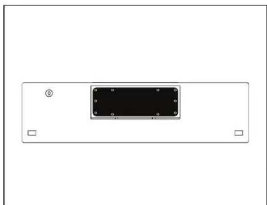
natural_image
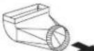
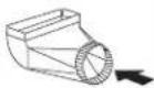
Top-down schematic of a rectangular device with internal components and mounting holes (no text or symbols)- Place 3-1/4"x10" rectangular collar on back of hood and secure using the screws that previously secured the rectangular cover plate.
Mounting the Hood
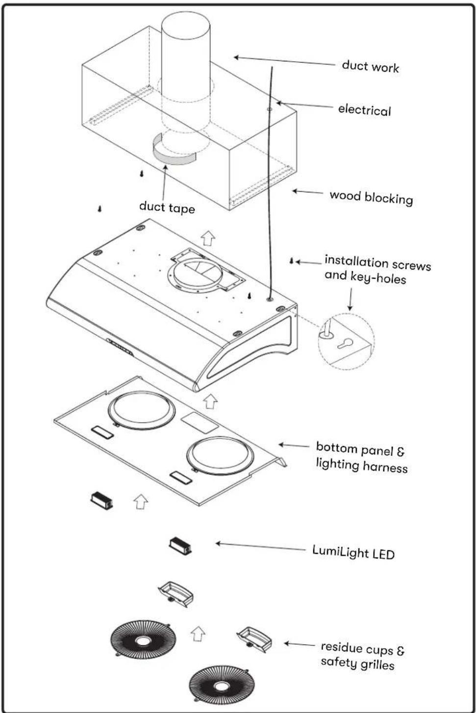
text_image
duct work electrical wood blocking duct tape installation screws and key-holes bottom panel & lighting harness LumiLight LED residue cups & safety grillesFIG. B
Mounting the Hood
Hood is designed for installation under a kitchen cabinet (FIG. B)
- Prepare duct location on hood (vertical or horizontal) Refer to Pages 11 for ducting options.
- Measure and cut out duct and electrical openings in cabinet or wall to match up with the hood. Ducting and electrical dimensions can be found on Pages 12-14. Note: Make sure duct opening is large enough to apply aluminum duct tape.
- Reinforce cabinet bottom with wood strips if additional strengthening is required or if cabinets are framed.
- Remove bottom panel from hood using a Philips head screwdriver to remove each of the screws. Also disconnect lighting harness by pressing in on the clip to release the lights from the internal wiring. Use caution when removing bottom panel. Take care not to scratch side panels during removal.
- Install (4) wood screws to cabinet bottom by following the installation screw hole dimensions on Page 12-14. These screws will be used to secure the hood to the cabinet.
- Lift hood onto screws located on cabinet bottom and lock into place. Make sure all (4) key-holes cover the screws. Tighten each screw to secure hood to cabinet. Note: For 30" Typhoon models you will need an 8" - 10" long shaft for your screwdriver/drill to reach the front screws.
- Install electrical.
- Install duct work and seal with aluminum duct tape.
- Power up hood and check for leaks around duct tape and test all functions.
- Reinstall bottom panel and re-connect lighting harness. Use caution when installing bottom panel. Take care not to scratch side panels during installation.
- Slide residue cups into their openings on the bottom of the hood. Install safety grilles over each blower opening and secure with the two safety grille screws.
AK21 Capacitive Touch
text_image
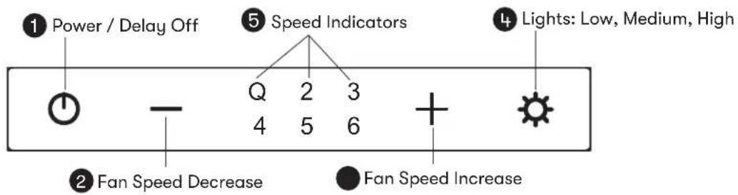
① Power / Delay Off ② Fan Speed Decrease ③ Speed Indicators ④ Lights: Low, Medium, High ⑤ Fan Speed Increase1 Power / Delay Off Button
- Button will turn power on and off for entire hood (fan and lights).
- Hood will remember the last speed and light level it was last turned off at.
(Example: Press button to turn off hood when on fan speed 3 and high lights.
Press button again and the hood will turn back on at speed 3 and high lights.)
Delay Off
- With the fan on, press and hold the ⏻ button for two seconds. The fan will change to speed Q and the 5 minute delay off timer will start.
- Speed indicators starting with level 5 will illuminate and blink in accordance with the time remaining until the fan an lights automatically turn off.
- Pressing ⏻ button while delay off function is enabled will turn the hood off and cancel the delay off function.
ACT Verification
- Airflow Control Technology (ACT) allows the installer to set the maximum fan CFM to align with local codes and regulations.
- To verify the maximum fan CFM:
- With hood off, hold the button for five seconds. If all speed level indicators illuminate = default maximum CFM. If speed Q, 2 & 3 level indicators illuminate = 390 maximum CFM. If speed Q & 2 level indicators illuminate = 290 maximum CFM.
② Fan Speed Decrease Button —
- Press this button to decrease fan speed. 6, 5, 4, 3, 2, Q (Quiet).
- If fan is off, press this button to turn on fan at last speed it was turned off at.
③ Fan Speed Increase Button +
- Press this button to increase fan speed. Fan on, Q (Quiet), 2, 3, 4, 5, 6
- If fan is off, press this button to turn on fan at last speed it was turned off at.
4 Lights Button ⚙️
- Lights have three levels, low, medium and high.
- From off, press one time for low, two times for medium, and three times for high.
5 Speed Level Indicators
- Fan is six speed levels. Q (Quiet), 2, 3, 4, 5 and 6.
AK25 Electronic Touch
text_image
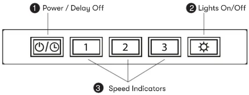
① Power / Delay Off ② Lights On/Off ③ Speed Indicators1 Power / Delay Off Button ⏻/➊
- ⏻/➊ Button will turn power on and off for entire hood (fan and lights.)
- Hood will remember the last speed and light level it was last turned off at.
(Example: Press button to turn off hood when on fan speed 3 and high lights.
Press 6/10 on again and the hood will turn back on at speed 3 and high lights.)
Delay Off
- With the fan on, press and hold the ⏻/➁ button for two seconds. The fan will change to speed 1, the ⏻/➁ button will blink on and off indicating the 5 minute delay off timer has started.
- Pressing ⏻/💡 button while delay off function is enabled will turn the hood off and cancel the delay off function.
ACT Verification
- Airflow Control Technology (ACT) allows the installer to set the maximum fan CFM to align with local codes and regulations.
- To verify the maximum fan CFM:
- With hood off, hold the button for five seconds. If all three fan speed indicators illuminate = default maximum CFM. If speed level 1 and 2 indicators illuminate = 390 maximum CFM. If only speed level 1 indicator illuminates = 290 maximum CFM.
② Lights Button
- Lights are two levels, high and low.
- From off, press one time for high. Press again for low. Press again to power lights off.
3 Speed Level Indicators
- Fan is three speed levels. 1 for low speed, 2 for medium speed, and 3 for high speed.
AK65 Mechanical Slide
① Blower On/Off Speed Selection
② Lights Off/Dim/Bright

1 BLOWER ON/OFF/SPEED SELECTION
0 is off, 1 is low speed, 2 is medium speed and 3 is high speed.
2 LIGHTS OFF/DIM/BRIGHT
0 is off, 1 is dim, and 2 is bright.
* ACT (Airflow Control Technology) is not available on AK65
Hood & Filter Cleaning
Self-cleaning Feature
Zephyr Typhoon, Hurricane and Cyclone hoods are filter-less with a self cleaning feature. The centrifugal blower system automatically liquefies cooking residue in its internal housing. All hoods are equipped with dishwasher safe residue cups to collect cooking residue during the self cleaning function.
Cooking residues are often automatically liquefied and can accumulate in the residue cups from everyday use. Nevertheless, grease from cooking could also dry and adhere to the internal housing. Running the self clean function periodically will flush out accumulated residue in the range hood's internal housing.
Cleaning Frequency
Cleaning should be performed approximately once a month under normal usage of 1 hour per day. The hood may need to be cleaned more often if you cook heavily.
Detergent
Use a grease cutting detergent such as Simple Green or 409.

WARNING

Use extreme caution while cleaning the hood. Beware of blowers catching on to hair, loose clothing and fingers. NEVER leave children unattended.
Hood & Filter Cleaning
Cleaning Instructions
text_image
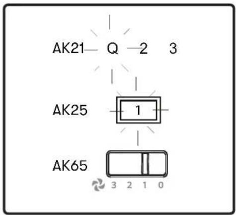
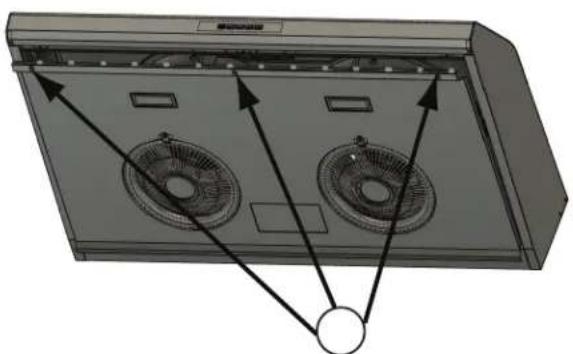
AK21—Q—2 3 AK25 1 AK65 3 2 1 0- Power on blowers at Speed 1.
natural_image
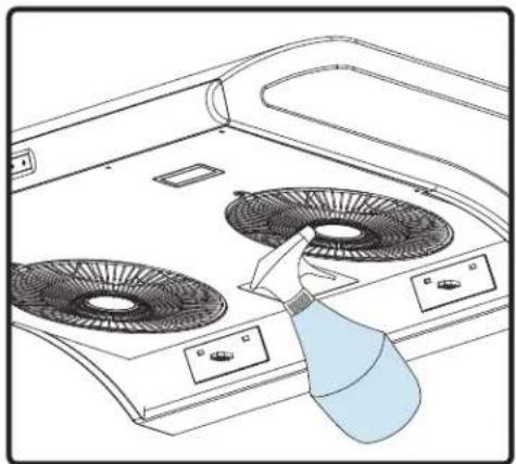
Line drawing of a stove interior with fans and a spray bottle (no text or symbols)- With nozzle on "spray", squirt grease cutting detergent onto blower wheel blades 30 - 35 times. Repeat for each blower. Leave blower on for 10 minutes. Detergent will collect in the residue cups.
natural_image
Line drawing of a front-mounted appliance with two fans and a control panel, showing no text or symbols.- Remove residue cups. Clean residue cups and in dishwasher or clean by hand. Install residue cups after cleaning.
Hood & Filter Cleaning
Surface Maintenance
▶ Do not use corrosive detergents, abrasive detergents or oven cleaners.
▶ Do not use any product containing chlorine bleach or any product containing chloride.
▶ Do not use steel wool or abrasive scrubbing pads which will scratch and damage surface.
Cleaning Stainless Steel
Clean periodically with warm soapy water and clean cotton cloth or micro fiber cloth. Always rub in the direction of the stainless steel grain. To remove heavier grease build up use a liquid degreaser detergent.
After cleaning use a non-abrasive stainless steel polish/cleaners, to polish and buff out the stainless luster and grain. Always scrub lightly, with clean cotton cloth or micro fiber cloth and buff in the direction of the stainless steel grain.
Cleaning Black Stainless Steel
Clean periodically with warm soapy water and clean cotton cloth or micro fiber cloth. To remove heavier grease build up use a liquid degreaser detergent.
Due to a built-in layer of protective anti-smudge coating, do not use stainless steel polish/cleaners to buff out black stainless steel.
LumiLight LED
In the unlikely event that your LumiLight LED or LED light strip fails, please contact Zephyr to order replacement parts.
See the list of parts and accessories page for part numbers and contact information.
LED Removal (FIG. C):
- Remove the screws from the bottom panel.
- Disconnect LED light quick connector.
- Push in the two side clips on the ends of the LED light.
- Push LED light through the light panel opening.
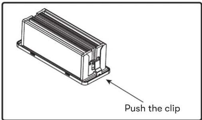
text_image
Push the clipFIG. C
Airflow Control Technology (ACT™)
Some local codes limit the maximum amount of CFM a range hood can move. ACT ^™ allows you to control the maximum blower CFM of select Zephyr Ventilation range hoods without the need for expensive make up air kits. ACT ^™ enables the installer to easily set the maximum blower speed to one of two most commonly specified CFM levels; 390 or 290 CFM. The usage of ACT ^™ may not be necessary for your installation. Please check your local codes for CFM restrictions.

CAUTION

Hood must be disconnected from the main power prior to performing the conversion instructions listed below. Failure to do so could result in personal injury or damage to the product.

CAUTION

After re-positioning the jumper and powering on the hood, the CFM cannot be changed again.
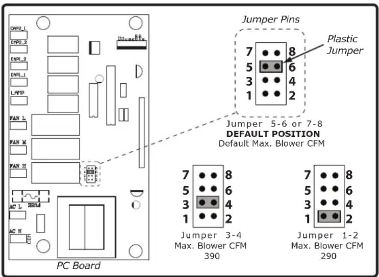
Enabling ACT™
To enable ACT™:
- Before hood installation, gain access to PC board by following the steps shown on FIG. D.
- Change plastic jumper positioning as shown in FIG. E to set the desired maximum blower CFM.
- Re-install PC board and continue with hood installation.
- Remove the appropriate foil CFM sticker included with the hood literature and place inside the hood body below the wiring diagram or in another clearly visible location.
To verify if your installer enabled ACT™:
-
Model Typhoon AK21: With hood off, hold down the power button for 5 seconds. If all speed level indicators illuminate = default max. CFM, if speed Q, 2 & 3 level indicators illuminate = 390 max. CFM, if speed Q & 2 level indicators illuminate = 290 max. CFM.
Model Hurricane AK25: With hood off, hold down the power button for 5 seconds. If all speed level indicators illuminate = default max. CFM, if speed 1 & 2 level indicators illuminate = 390 max. CFM, if speed 1 level indicator illuminate = 290 max. CFM -
When ACT ^™ is enabled, the number of blower speeds will be reduced as follows:
Model Typhoon AK21: 390 CFM = max. 3 speeds, 290 CFM = max. 2 speeds
Model Hurricane AK25: 390 CFM = max. 2 speeds, 290 CFM = max. 1 speed
- There should also be a foil label located inside the hood body near the wiring diagram that indicates the blower CFM.
text_image
Jumper Pins Plastic Jumper Jumper 5-6 or 7-8 DEFAULT POSITION Default Max. Blower CFM 7 8 5 6 3 4 1 2 Jumper 3-4 Max. Blower CFM 390 Jumper 1-2 Max. Blower CFM 290 PC BoardFIG. E
Accessing PC Board Instructions
NOTE: Take care when removing PC board as there are many wires connected to the board.
Model: Typhoon AK21
- Remove bottom panel by 6 screws (FIG. D1) and disconnect LED light quick connectors.
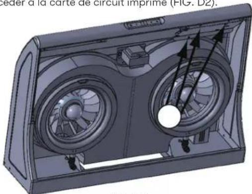
- Remove 3 screws securing PC board plate to access PC board (FIG. D2).
natural_image
Diagram of a vehicle's air conditioning unit showing fan airflow paths (no text or labels)FIG. D1
natural_image
3D rendering of a car air vent system with fan blades and airflow arrows (no text or symbols)FIG. D2
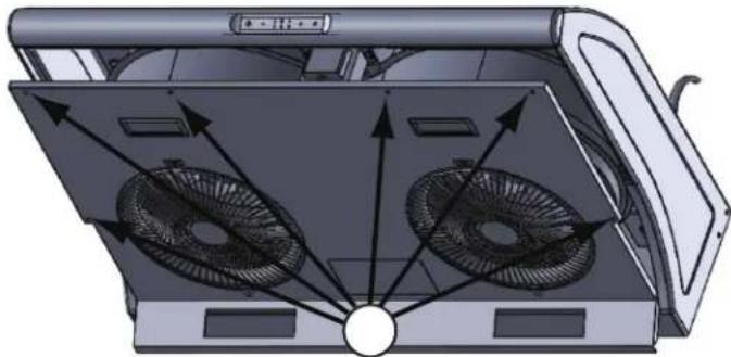
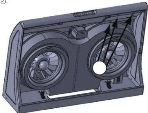
Model: Hurricane AK25
- Remove bottom panel by 3 screws (FIG. D3) and disconnect light socket connectors.
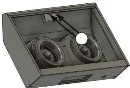
- Remove PC board plate by 2 screws (FIG. D4).
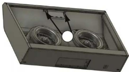
- Remove 2 screws securing PC board assembly to access PC board (FIG. D5).
natural_image
3D diagram of a server rack with two fans and a circular component, no text or symbols presentFIG. D3
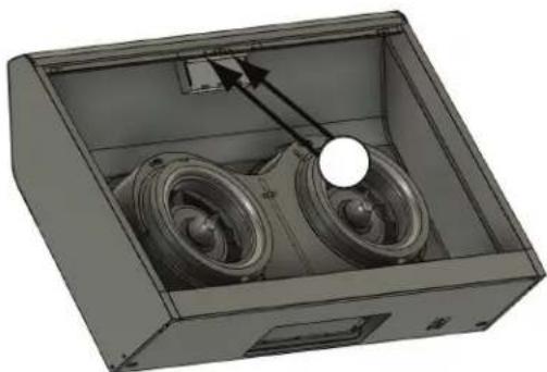
natural_image
3D rendering of an open industrial enclosure with two speaker wheels and a central hub (no text or symbols visible)FIG. D4
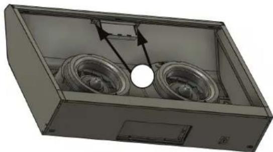
natural_image
3D rendering of a mechanical housing with two circular components and directional arrows indicating flow or movement (no text or symbols)FIG. D5
text_image
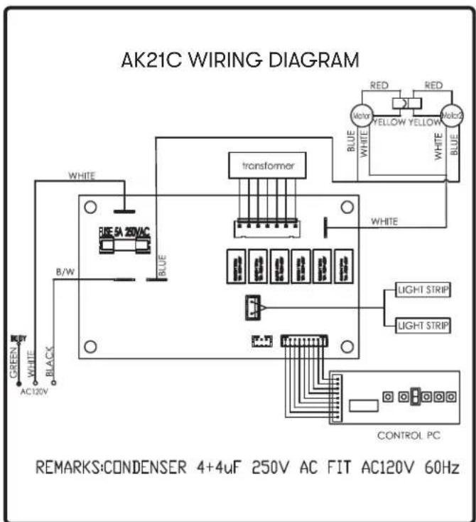
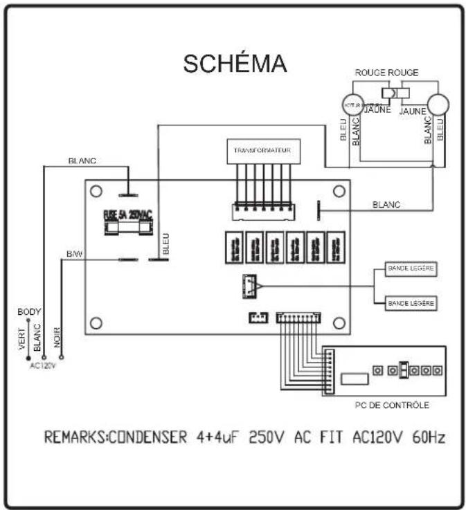
AK21C WIRING DIAGRAM GREEN WHITE BLACK B/W WHITE BLUE BE SA 20VAC transformer WHITE RED RED Moto YELLOW YELLOW Molo2 WHITE WHITE LIGHT STRIP LIGHT STRIP CONTROL PC REMARKS:CONDENSER 4+4uF 250V AC FIT AC120V 60Hz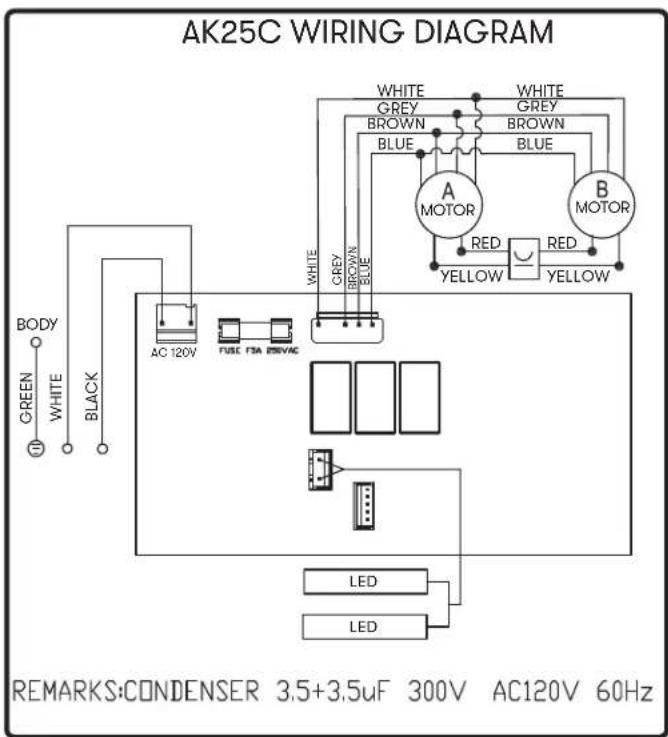
text_image
AK25C WIRING DIAGRAM BODY GREEN WHITE BLACK AC 120V FUSE FSA EAVAC WHITE GREY BROWN BLUE WHITE GREY BROWN BLUE A MOTOR RED YELLOW B MOTOR RED YELLOW REMARKS:CONDENSER 3.5+3.5uF 300V AC120V 60Hz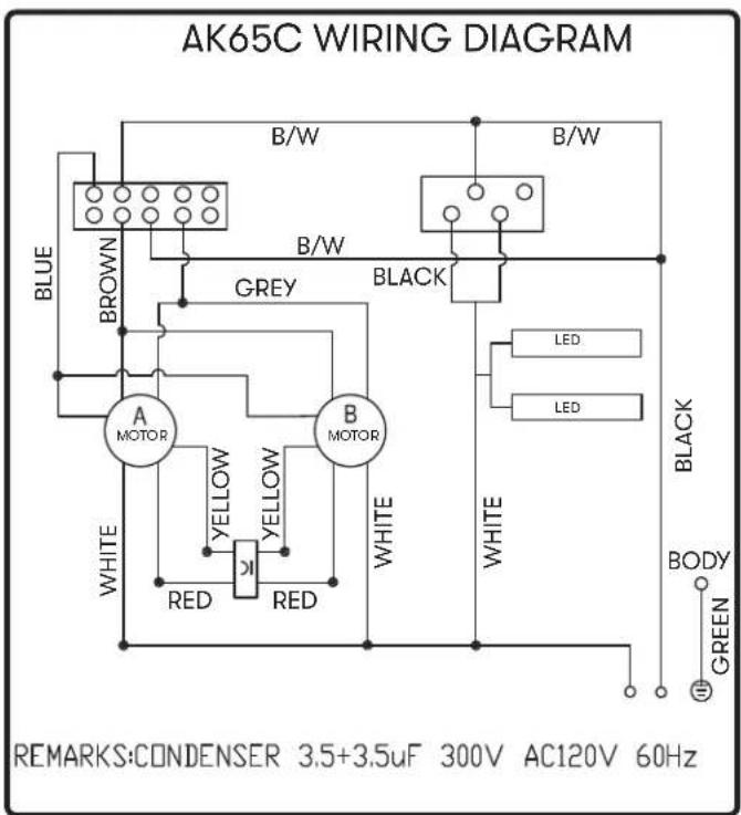
text_image
AK65C WIRING DIAGRAM B/W B/W BLUE BROWN B/W GREY BLACK A MOTOR B MOTOR WHITE YELLOW K RED RED WHITE LED LED BLACK BODY GREEN REMARKS:CONDENSER 3.5+3.5uF 300V AC120V 60Hz| Possible Problem Possible Cause Solutions | ||
| After installation, the unit doesn't work. | The power source is not turned ON. Make sure the circuit breaker and the unit's power is ON. | |
| The power line and the cable locking connector is not connecting properly. | Check the power connection with the unit is connected properly. | |
| The switch board or control board wirings are disconnected. | Make sure the wirings at the switch board and control board are connected properly. | |
| The switch board or control board is defective. | Change the switch board or control board. | |
| Light works, but blower is not turning. | The blower cable is disconnected. Connect the blower cable. | |
| Debris or obstruction in motor. Remove the debris or obstruction. | ||
| Motor defective or possibly seized. Change the blower. | ||
| Damaged capacitor. Change the capacitor. | ||
| The switch board or control board is defective. | Change defective part. | |
| The unit is vibrating. The blower is not secured in place. Tighten the blower in place. | ||
| The hood is not secured in place. Check the installation of the hood. | ||
| The blower is working, but the lights are not. | The LED light connector is disconnected. | Connect the LED light connector. |
| Defective LED light. Change the LED light. | ||
| The switch board or control board is defective. | Change the switch board or control board. | |
| LumiLight LEDs flicker when changing speed levels. | N/A | This is a normal operation and the hood is working correctly. |
| The hood is not venting out properly. | Using the wrong type of ducting. Flexible ducting can reduce air flow by up to 50%. | Change the ducting to solid rigid metal ducting. |
| The hood might be hanging to high from the cook top. | Adjust the distance between the cook top and the bottom of the hood within 24" and 32" range. | |
| The wind from the opened windows or opened doors in the surrounding area are affecting the ventilation of the hood. | Close all the windows and doors to eliminate the outside wind flow. | |
| Blockage in the duct opening or ductwork. | Remove all the blocking from the duct work or duct opening. | |
| The unit turns on by itself. | A spot light or kitchen lamp is shining directly onto the switch controls. | The switch controls are light sensitive. A direct light source onto the switch controls may disrupt switch functions. |
| Safety grille is vibrating. | Safety grille is loose. | Tighten safety grille screw. |
| Description Part Number | |
| Replacement Parts | |
| LumiLight LED, 6W (AK21 & AK25) Z0B0047 | |
| LumiLight LED, 6W (AK65) Z0B0049 | |
| Residue Cup (AK21) 56160003 | |
| Residue Cup (AK25 & AK65) 56160007 | |
| Safety Grille Stainless (AK21) 50220024 | |
| Safety Grille Black (AK21) 50220025 | |
| Safety Grille White (AK21) 50220026 | |
| Safety Grille Stainless (AK25 & AK65) | 50220022 |
| Safety Grille Black (AK25 & AK65) 50220027 | |
| Safety Grille White (AK25 & AK65) 50220023 | |
| Optional Accessories | |
| Make-up Air Kit (AK21 & AK25) MUA008A | |
| Make-up Air Kit (AK65) MUA006A | |
To order parts, visit us online at http://store.zephyronline.com or call us at 1.888.880.8368.
TO OBTAIN SERVICE UNDER WARRANTY OR FOR ANY SERVICE RELATED QUESTIONS, please call: 1-888-880-8368
Zephyr Ventilation, LLC (referred to herein as "we" or "us") warrants to the original consumer purchaser (referred to herein as "you" or "your") of Zephyr products (the "Products") that such Products will be free from defects in materials or workmanship as follows:
Ten Year Limited Warranty for Parts: For ten years from the date of your original purchase of the Products, we will provide, free of charge, Products or parts (including LED light bulbs, if applicable) to replace those that failed due to manufacturing defects. We may choose, in our sole discretion, to repair or replace parts before we elect to replace the Products.
One Year Limited Warranty for Labor: For one year from the date of your original purchase of the Products, we will provide, free of charge, the labor cost associated with repairing the Products or parts to replace those that failed due to manufacturing defects. After the first year from the date of your original purchase, you are responsible for all labor costs associated with this warranty.
Warranty Exclusions: This warranty covers only repair or replacement, at our option, of defective Products or parts and does not cover any other costs related to the Products including but not limited to: (a) normal maintenance and service required for the Products and consumable parts such as fluorescent, incandescent or halogen light bulbs, mesh and charcoal filters and fuses; (b) any Products or parts which have been subject to freight damage, misuse, negligence, accident, faulty installation or installation contrary to recommended installation instructions, improper maintenance or repair (other than by us); (c) commercial use of the Products or use otherwise inconsistent with its intended purpose; (d) natural wear of the finish of the Products or wear caused by improper maintenance, use of corrosive and abrasive cleaning products, pads, and oven cleaner products; (e) chips, dents or cracks caused by abuse or misuse of the Products; (f) service trips to your home to teach you how to use the Products; (g) damage to the Products caused by accident, fire, floods, acts of God; or (h) Custom installations or alterations that impact serviceability of the Products. If you are outside our service area, additional charges may apply for shipping costs for warranty repair at our designated service locations and for the travel cost to have a service technician come to your home to repair, remove or reinstall the Products. After the first year from the date of your original purchase, you are also responsible for all labor costs associated with this warranty.
Limitations of Warranty. OUR OBLIGATION TO REPAIR OR REPLACE, AT OUR OPTION, SHALL BE YOUR SOLE AND EXCLUSIVE REMEDY UNDER THIS WARRANTY. WE SHALL NOT BE LIABLE FOR INCIDENTAL, CONSEQUENTIAL OR SPECIAL DAMAGES ARISING OUT OF OR IN CONNECTION WITH THE USE OR PERFORMANCE OF THE PRODUCTS. THE EXPRESS WARRANTIES IN THE PRECEDING SECTION ARE EXCLUSIVE AND IN LIEU OF ALL OTHER EXPRESS WARRANTIES. WE HEREBY DISCLAIM AND EXCLUDE ALL OTHER EXPRESS WARRANTIES FOR THE PRODUCTS, AND DISCLAIM AND EXCLUDE ALL WARRANTIES IMPLIED BY LAW, INCLUDING THOSE OF MERCHANTABILITY AND FITNESS FOR A PARTICULAR PURPOSE. Some states or provinces do not allow limitations on the duration of an implied warranty or the exclusion or limitation of incidental or consequential damages, so the above limitations or exclusions may not apply to you. To the extent that applicable law prohibits the exclusion of implied warranties, the duration of any applicable implied warranty is limited to the same ten-year period described above. Any oral or written description of the Products is for the sole purpose of identifying the Products and shall not be construed as an express warranty. Prior to using, implementing or permitting use of the Products, you shall determine the suitability of the Products for the intended use, and you shall assume all risk and liability whatsoever in connection with such determination. We reserve the right to use functionally equivalent refurbished or reconditioned parts or Products as warranty replacements or as part of warranty service. This warranty is not transferable from the original purchaser and applies in the United States and Canada.
To Obtain Service Under Limited Warranty: To qualify for warranty service, you must: (a) notify us at the address or telephone number stated below within 60 days of the discovery of the defect; (b) give the model number and part identification number and serial number; and (c) describe the nature of any defect in the Product or part. At the time of the request for warranty service, you must present evidence of your proof of purchase and proof of the original purchase date. If we determine that the warranty exclusions listed above apply or if you fail to provide the necessary documentation to obtain service, you will be responsible for all shipping, travel, labor and other costs related to the services.
Please check our website for any revisions, www.zephyronline.com.
Zephyr Ventilation Service Department, 2277 Harbor Bay Parkway, Alameda, CA 94502 1-888-880-8368
DEC20.0401
Congratulations on the purchase of your Zephyr product! Please take a moment to register your new Zephyr product at www.zephyronline.com/registration
IT'S IMPORTANT
Prompt registration helps in more ways than one.
- Ensures warranty coverage should you need service.
- Ownership verification for insurance purposes.
- Notification of product changes or recalls.

text_image
STOPZephyr Ventilation | 2277 Harbor Bay Pkwy. | Alameda, CA 94502 | 1.888.880.8368
Typhoon
AK2100CS, B, W
AK2136CS, B, W
AK2142CS
AK2148CS
ACT
natural_image
Technical line drawing of a mechanical housing component with mounting holes and a central circular recess (no text or symbols)Hurricane
AK2500CS, B, W
AK2536CS, B, W
ACT Airflow Central Technology
natural_image
Isometric line drawing of a rectangular metal enclosure with a circular opening and mounting holes (no text or symbols)Cyclone
AK6500CS, B, BS, W
AK6536CS, B, BS, W
AK6542CS

natural_image
Isometric line drawing of a rectangular metal enclosure with a circular recess and mounting holes (no text or symbols)EN Use, Care, and Installation Guide
* National Fire Protection Association Batterymarch Park, Quincy, Massachusetts 02269
** CSA International 8501 East Pleasant Valley Road, Cleveland, Ohio 44131-5575
Pièces fournies
natural_image
Technical drawing of a mechanical component with mounting holes and a central circular feature (no text or symbols)natural_image
Pure technical diagram of a mechanical component with mounting holes and a central curved housing (no text or symbols)natural_image
Top-down schematic of a basketball court with a central black dome and surrounding corner markers (no text or symbols)natural_image
Technical diagram of a mechanical component with mounting holes and a central circular feature (no text or symbols)natural_image
Top-down schematic view of a rectangular device with a central black component and two mounting holes (no text or symbols)natural_image
Diagram of a mechanical component with arrows indicating direction (no text or symbols)natural_image
Pure technical diagram of a mechanical component with mounting holes and a central semicircular feature (no text or symbols)natural_image
Pure technical diagram of a mechanical component with mounting holes and a central semicircular feature (no text or symbols)natural_image
Simple line drawing of a rectangular frame with a central rectangular cutout and corner markers (no text or symbols)natural_image
Line drawing of a stove interior with two fans and a spray bottle (no text or symbols)natural_image
Line drawing of a front-mounted appliance with three fans and a control panel, showing no text or symbols.Retrait de la LED LumiLight (FIG. C):
natural_image
Diagram of a vehicle air conditioning unit with fan blades and airflow arrows (no text or symbols)FIG. D1
natural_image
Diagram of a car air vent system with fan blades and airflow arrows (no text or labels)FIG. D2
natural_image
3D diagram of a server rack with two fans and a circular component, no text or symbols presentFIG. D3
natural_image
3D rendering of a mechanical housing with two circular components and an arrow indicating direction (no text or symbols)FIG. D4
natural_image
3D rendering of a mechanical housing with two circular components and directional arrows indicating flow or movement (no text or symbols)FIG. D5
text_image
SCHÉMA ROUGE ROUGE CTP JAONE JAUNE BLANC BLANC TRANSFERNATEUR BRE SA 250VAC BLEU B/W BODY BLANC NOIR AC120V PC DE CONTROLE BANCE LEGÈRE BANCE LEGÈRE REMARKS:CONDENSER 4+4uF 250V AC FIT AC120V 60Hz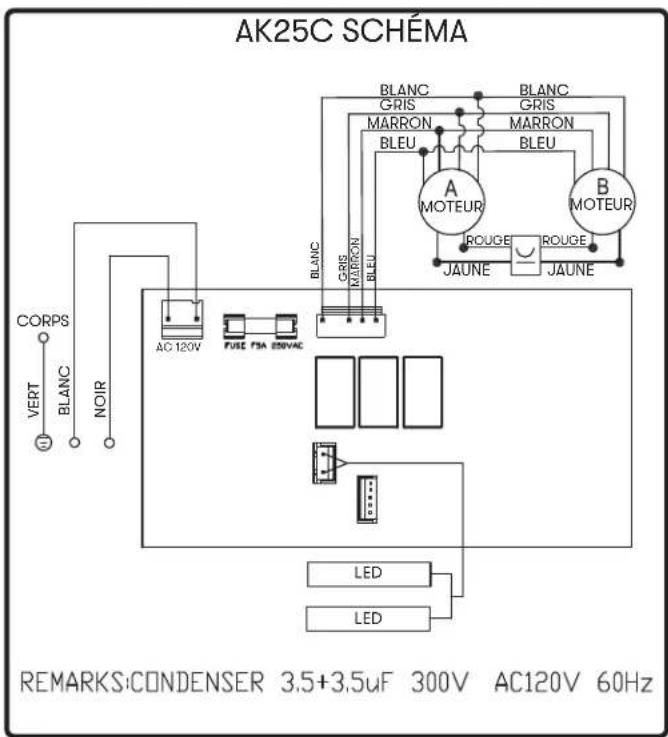
text_image
AK25C SCHÉMA BRANCH GRIS MARRON BLEU A MOTEUR B MOTEUR BLANC GRIS MARRON BLEU ROUGE ROUGE JAUNE JAUNE BRANCH GRIS MARRON BLEU AC 120V FUSE PBA ESRVAC CORPS VERT BLANC NOIR LED LED REMARKS:CONDENSER 3.5+3.5uF 300V AC120V 60Hz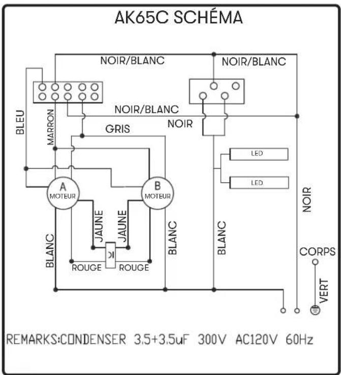
text_image
AK65C SCHÉMA NOIR/BLANC NOIR/BLANC MARRON GRIS NOIR A MOTEUR B MOTEUR JAUNE JAUNE ROUGE ROUGE BLANC BLANC LED LED NOIR CORPS VERT REMARKS:CONDENSER 3.5+3.5uF 300V AC120V 60HzZephyr Ventilation Service Department, 2277 Harbor Bay Parkway, Alameda, CA 94502 1-888-880-8368
DEC20.0501