Prodigy Plus C1848 - Ice Maker Scotsman - Free user manual and instructions
Find the device manual for free Prodigy Plus C1848 Scotsman in PDF.


| Product Type | Modular Ice Machine |
| Brand | Scotsman |
| Model | Prodigy Plus C1848 |
| Production Capacity | Up to 816 kg (1800 lb) per 24 hours |
| Ice Type | Cubes (small or medium depending on version) |
| Nominal Width | 121.9 cm (48 inches) |
| Power Supply | 230 V / 50 Hz / single phase |
| Ambient Temperature Range | 10°C to 38°C |
| Water Temperature Range | 4°C to 38°C |
| Required Water Pressure | 1 to 5 bar |
| Water Inlet Connection | 3/4" gas BSPP (19 mm) |
| Drain Connection | 3/4" FPT (19 mm) |
| Condenser Type | Air or water cooled depending on version |
| Main Features | AutoAlert indicator lights, automatic shut-off, adjustable drain, Vari-Smart and SmartBoard options |
| Maintenance and Cleaning | Clean and disinfect water system at least twice a year; washable air filter; replace water filter every 6 months |
| Safety | Mandatory grounding; low water protection |
| Panel Material | Stainless steel |
| Operating Noise | Compressor, pump, fans, and ice drop noise |
| Warranty | According to separate leaflet provided with the unit |
| Installation | Indoor, controlled environment, minimum 150 mm clearance on sides and back |
Frequently Asked Questions - Prodigy Plus C1848 Scotsman
User questions about Prodigy Plus C1848 Scotsman
0 question about this device. Answer the ones you know or ask your own.
Ask a new question about this device
Download the instructions for your Ice Maker in PDF format for free! Find your manual Prodigy Plus C1848 - Scotsman and take your electronic device back in hand. On this page are published all the documents necessary for the use of your device. Prodigy Plus C1848 by Scotsman.
USER MANUAL Prodigy Plus C1848 Scotsman
Scotsman® Ice Systems
Installation Manual Manuale di installazione Manual de instalación Manuel d'installation Installationsanleitung
Models, Modelli, Modelos, Modèles, Modelle C1448, C1848, C2148W
Introduction
The design of this modular cuber is the result of years of experience and testing. Standard features include front accessible indicator lights and on-off switches that provide the user with fast access to critical information and easy operational control. When desired, optional controls can add features like ultrasonic bin ice level sensing, seven day programmable bin ice level setting, remote lock out and more.
This installation and user manual is divided into three main sections: Installation, which provides the trade person with the information needed to set up and install this product; Use and Operation, which provides the user with the information to use the product; and Maintenance, which provides the user with the information needed keep it operating efficiently.
Table of Contents
| Installation: Product Specifications | Page 2 |
| Product Information | Page 3 |
| Water | Page 4 |
| Panel Removal | Page 5 |
| Uncrate and Set Up | Page 6 |
| Plumbing Requirements | Page 7 |
| Electrical | Page 8 |
| Initial Start Up | Page 9 |
| Adjustments | Page 10 |
| Use and Operation | Page 11 |
| Water flush setting | Page 12 |
| Switches | Page 13 |
| Options and Other Information | Page 14 |
| Cleaning, Sanitation and Maintenance | Page 15 |
| What to do before calling for service | Page 16 |
Note any Caution or Warning symbols when they appear on the product or in this manual. They indicate potential hazards.
Installation: Product Specifications
Location Limitations: The product is designed to be installed indoors, in a controlled environment. Air cooled models discharge very warm air into the room out the back. Space must be allowed at the left side and back for air intake and discharge. Water cooled models discharge warm water into the building's drain. Space needs to be provided on both sides and above for service access.
Space Limitations
Note: Although the machine will function, ice capacity of air cooled machines will be significantly reduced with minimal clearance at the sides, back and top. Some space is recommended for service and maintenance purposes on all models.
6" of space at the sides and back are required for adequate operation. To get the most capacity, locate the machine away from heat producing appliances and heating ducts. Provide several feet of space to the left for maximum ice capacity.
Walls or other large machines near to the ice machine might also cause a reduction in ice capacity. One foot behind and two feet above will be required to make rated capacity.
Airflow is in the front, in the left side, out the back (as viewed from the front).
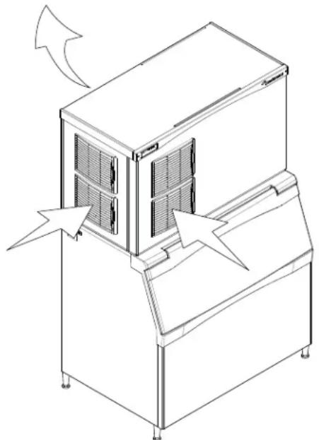
Airflow Direction
Environmental Limitations
| Minimum Maximum | ||
| Air temperature 10 | °C. 38 | °C. |
| Water temperature | 4°C. 38 | °C. |
| Water pressure 1 | bar 5 bar | |
Power supply – acceptable voltage ranges
| Minimum Maximum | ||
| 230 volt model | 207 volts | 253 volts |
Power Cord Reference Table
| Rated Current of Model | Nominal Cross-Sectional Area (mm 2 ) of Conductors |
| 3,1 through 6 amperes | ,75 |
| 6,1 through 10 amperes 1,0 | |
| 10,1 through 16 amperes | 1,5 |
| 16,1 through 25 amperes | 2,5 |
Warranty Information
The warranty statement for this product is provided separately from this manual. Refer to it for applicable coverage. In general warranty covers defects in material or workmanship. It does not cover maintenance, corrections to installations, or situations when the machine is operated in circumstances that exceed the limitations printed above.
Product Information
The product is a modular cuber. That type of machine is designed to be placed on an ice storage bin or an ice dispenser. Many installations only require the matching bin, but some also require an adapter to be placed between the bin and the cuber or between the dispenser and the cuber.
This product cannot be stacked. See the chart for application information.
Model Number Description
Example:
C1448MA-6A
• C= cuber
• 14= nominal ice capacity in 100s of pounds
• 48= nominal width of cabinet
- S= Cube size. S=small or half dice cube. M=medium or full dice cube
- A=Condenser type. A=air cooled. W=water cooled
-6=230/50/1
• A=Series revision code. A=first series
Note: In some areas of this manual model numbers may include only the first five characters of the model number, meaning that the cube size, condenser type and voltage differences are not critical to the information listed there.
Options:
There are several field-installed options that can be installed at initial start up or later. They include:
- Vari-Smart™ adjustable ice level system.
- SmartBoard™advanced feature control.
Some installations require bin adapters. See the table below.
Standard Bin Applications - Adapter information.
| Model BH900*, B948S | BH1100, BH1300, BH1600 | |
| C1448, C1848, C2148 | Direct Fit, no adapter needed | No adapter needed |
* Note. If previously equipped with stainless steel baffle, KBAFFLE3, remove and replace with original plastic baffle.
Other Bins & Applications:
Note the drop zone and ultrasonic sensor locations in the illustrations.
Scotsman assumes no liability of responsibility of any kind for products manufactured by Scotsman that have been altered in any way, including the use of any part and/or other components not specifically approved by Scotsman.
Scotsman reserves the right to make design changes and/or improvements at any time. Specifications and design are subject to change without notice.
Water
The quality of the water supplied to the ice machine will have an impact on the time between cleanings and ultimately on the life of the product. There are two ways water can contain impurities: in suspension or in solution. Suspended solids can be filtered out. In solution or dissolved solids cannot be filtered, they must be diluted or treated. Water filters are recommended to remove suspended solids. Some filters have treatment in them for suspended solids. Check with a water treatment service for a recommendation.
Scotsman filters:
A triple head filter is recommended for the potable water. Either the Scotsman SSM3 taste and odor filter system, or the ADS-AP3 Aqua Patrol system.
RO water. This machine can be supplied with Reverse Osmosis water, but the water conductivity must be no less than 10 microSiemens/cm.
Condenser Water Supply - filtration not recommended for this water supply
Potential for Airborne Contamination
Installing an ice machine near a source of yeast or similar material can result in the need for more frequent sanitation cleanings due to the tendency of these materials to contaminate the machine. Most water filters remove chlorine from the water supply to the machine which contributes to this situation. Testing has shown that using a filter that does not remove chlorine, such as the Scotsman Aqua Patrol, will greatly improve this situation, while the ice making process itself will remove the chlorine from the ice, resulting in no taste or odor impact. Additionally, devices intended to enhance ice machine sanitation, such as the Scotsman Aqua Bullet, can be placed in the machine to keep it cleaner between manual cleanings
Water Flush
Cube ice machines use more water than what ends up in the bin as ice. While most water is used during ice making, a portion is designed to be drained out every cycle to reduce the amount of hard water scale in the machine. That's known as water flush, and an effective flush can increase the time between needed water system cleaning.
In addition, this product is designed to automatically vary the amount of water flushed based on the purity of the water supplied to it. The water flush rate can also be set manually. Adjustments of flush due to local water conditions are not covered by warranty.
Uncrate and Set Up
Begin with unpacking the ice storage bin. Remove the carton, and using part of the carton as a cushion, tip the bin on its back to remove the skid and attach the legs or casters.
Note: Turn the leg levelers in all the way and adjust after the ice machine is on top and in its selected location.
Return the bin to an upright position. Check the bin top gasket for gaps and tears, fill any in with food grade sealant prior to placing the ice machine on the bin.
Install the bin top adapter if one is required for the application.
If the ice machine has not been unpacked, do so now. Remove the carton from the skid. Lift the ice machine off the skid directly onto the bin.
Note: The machine is heavy! Use a mechanical hoist if necessary.
Secure the ice machine to the bin with the hardware provided (two metal straps and 4 bolts).
Level the bin and ice machine using the adjustment part of the legs.
Bin Recycling
Many times an ice machine head will be replaced, while the existing ice storage bin will be reused. This is an acceptable practice, if some precautions are taken:
- The used bin must be in good condition. Broken doors, hinges, or warped walls are reason for considering a new bin.
- The used bin top edge gasket must be replaced. Water leaks could occur if the gasket tape is not replaced.
The used bin should be the proper size for the ice machine head.
Switch Bezel
All models ship with the On and Off switches front accessible. if desired, the On and Off switches can be covered up to prevent unauthorized use by changing the bezel in the front panel's trim strip. A cover-up bezel ships loose with the machine.
To change bezels: Remove the front panel and refer to the instruction label on the inside of the front panel. Push snaps of the standard bezel in and pull the bezel out of the front panel. Locate other bezel. Push into trim strip from the front until it snaps into place. Return the front panel to its original position and secure it to the cabinet.
Plumbing Requirements
All models require connection to cold, potable water. A hand actuated valve within site of the machine is required. Air cooled models have a single 3/4 gas BSPP inlet water connection.
Warning: All models require connection to potable water.
Water cooled models have the same inlet fitting plus an additional 3/8" FPT condenser inlet water connection.
Drains
All models require drain tubing to be attached to them. Air cooled models have a single 3/4 " FPT drain fitting in the back of the cabinet. Water cooled models have the same fitting plus an additional 1/2 " FPT drain fitting in the back of the cabinet.
Install new tubing when replacing a prior ice machine, as the tubing will have been sized for the old model and might not be correct for this one.
1 Connect water supply to water inlet fittings.
2 Connect drain tubing to drain fittings.
3 Route the drain tubing to building drain. Follow local codes for air gap.
Use rigid drain tubes and then route them separately – do not Tee into the bin's drain or, if water cooled, Tee the condenser drain into the reservoir or bin drain.
Vent the reservoir drain. A vertical vent at the back of the drain, extended about 200 mm will allow the gravity drain to empty and also keep any surges during draining from discharging water.
Horizontal runs of drain tubing need a 6 mm fall per meter of run for proper draining.
Follow all applicable codes.
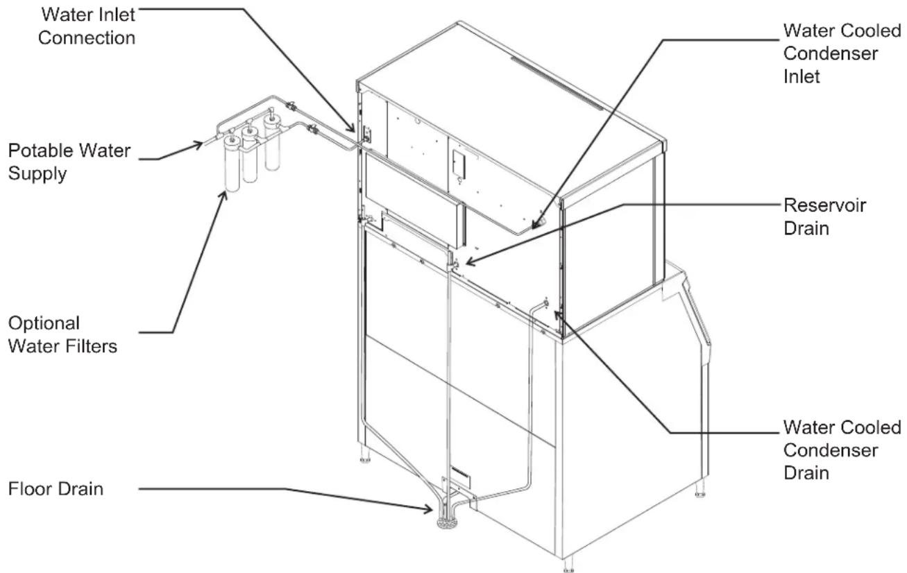
Water Supply and Drain Connections
Electrical
Power Cord Installation:
- Select and obtain the proper power cord of type H03RT-F, H05RR-F, H03VV-F, H03VVH2-F or heavier. Ground wire must be green/yellow color. Only one cord per plug. See Power Cord Reference Table for suggested cord sizing.
- Electrical supply circuit must be dedicated to this machine. Do not connect to a circuit powering any other device. Product should only have one supply means.
- Remove the junction box cover.
- Install a field supplied, non-detachable, non-metallic strain relief per code. Strain relief must be properly sized for the OD of the power cord and the ID of the routing hole.
- Route the power cord through the access hole / strain relief and properly attach the power supply wires. Do not tin the leads. Strip 6 mm of power cord lead insulation and properly attach power cord wires to the lead wires in the junction box.
- Connect an electrical plug of the proper type for the application and country of use.
Power Cord Replacement:
Notice: In case the power cable is damaged, it must be replaced ONLY by QUALIFIED TECHNICIANS to prevent any possible risks.
- Disconnect electrical power to machine.
- Remove junction box cover.
- Disconnect and remove existing power cord.
- Select and obtain the proper power cord of type H03RT-F, H05RR-F, H03VV-F, H03VVH2-F or heavier. Ground wire must be green/yellow color. Only one cord per plug. See Power Cord Reference Table for suggested cord sizing.
- Install a field supplied, non-metallic, non-detachable strain relief per code.
- Route the power cord through the access hole / strain relief and properly attach the power supply wires. Do not tin the leads. Strip 6 mm of power cord lead insulation and properly attach power cord wires to the lead wires in the junction box.
- Connect an electrical plug of the proper type for the application and country of use.
- Attach a ground wire to the ground connection in the junction box. Note: Ground wire must be longer than power lead wires.
- Reconnect power supply. Check voltage when complete.
- Return the junction box cover to its original position and secure with the original screws.
Final Check List
After connections,
1 Wash out the bin. If desired, the interior of the bin could be sanitized.
2 Locate the ice scoop (if supplied) and have it available for use when needed.
Final Check List:
1 Is the unit located indoors in a controlled environment?
2 Is the unit located where it can receive adequate cooling air?
3 Has the correct electrical power been supplied to the machine?
4 Have all the water supply connections been made?
5 Have all the drain connections been made?
6 Has the unit been leveled?
7 Have all unpacking materials been removed?
8 Is the water pressure adequate?
9 Have the drain connections been checked for leaks?
10 Has the bin interior been wiped clean or sanitized?
11 Have any water filter cartridges been replaced?
12 Have all required kits and adapters been properly installed?
Initial Start Up
1 Remove front panel. Check machine for any packing or wires rubbing moving parts. Note location of control board in upper left corner of the machine's front.
2 Remove tape securing each curtain to its evaporator.
3 Switch on the electrical power to the machine. Observe that some of the control's indicator lights glow and its display shows 0.
4 Open the water supply valve.
5 Push and release the ON button. The indicator light will begin to blink F.
The flush valve will open and the water pump will start. The inlet water valve will open to add water to the reservoir. After a few seconds the flush valve will close and the water pump will stop. Water will flow into the machine until the reservoir is full. The hot gas valves and harvest assist devices will activate then the compressor and water pump will start. If its an air cooled model the fan(s) motors will begin to turn. The display will show a continuous F. Five seconds later the hot gas valves will close and the harvest assist device will return to its standby position. Warm air will be discharged from air cooled models.
6 Observe the Ready for Harvest indicator light. It may blink early in the cycle, that is normal. The control will ignore that signal for the first 6 minutes of freeze.
7 During the Freeze cycle open and close the curtains. The SW1 and SW2 lights on the control board will blink ON when each curtain is opened and OFF when closed.
Note: Moving a curtain during the Freeze cycle has no affect on the control, but will cause water to flow into the cube chute.
8 When the ice has frozen enough, the Ready for Harvest indicator light will be on steady. After it's been on steady for a few seconds Harvest will begin.
9 The display shows an H.
The hot gas valves open, the air cooled fan motors shut off and the harvest assist mechanisms are activated. The flush valve opens to drain some water, when it does the inlet water valve opens to refill the reservoir. After a few seconds the flush valve closes but the inlet water valve continues to fill the reservoir. Harvest continues until the ice is released as a unit and forces the curtain to open. When both curtains re-close the controller returns the unit to a freeze cycle.
10 Check the ice harvested for proper bridge thickness. The ice bridge is factory set at 3/16 inch. If needed, adjust bridge thickness. Do NOT make it too thin.
11 Determine the water flush setting from the table below. If desired, change the setting to accommodate the local water conditions.
12 Return the front panel to its normal position and secure it to the machine.
13 Instruct the user in the operation of the machine and its maintenance requirements.
14 Fill out and mail warranty registration form.
Typical Ice Making Cycle Times (minutes).
Listed times are for clean machines in proper installations. Cycle length at start up will be longer until the system stabilizes.
| Model | 21°C. air / 10°C. water | 32°C. air / 21°C. water |
| C1448A 12-14 | 14-16 | |
| C1448W 13-15 | 14-16 | |
| C1848A 9-11 | 12-14 | |
| C1848W 9-11 | 10-12 | |
| C2148W 9-11 | 10-12 |
Adjustments
Bridge Thickness - For Service Tech Only
1 Push and hold Off till the machine stops.
2 Remove evaporator cover.
3 Remove curtain.
4 Use a box wrench and rotate the bridge thickness adjustment screw in 1/8 turn increments CW to increase bridge thickness. Rotate CCW to decrease bridge thickness.
Caution: Do not make the bridge too thin or the machine will not harvest properly. Bridge thickness adjustments are not covered by warranty.
5 Return curtain to its normal position.
6 Push and release the On button. Check next harvest of ice. Repeat steps 1-6 if needed.
Note: Water cooled models, the refrigeration system discharge pressure is factory set at 245 PSIG, which should yield a freeze cycle discharge water temperature of about 105-110 degrees F. Adjust if necessary.
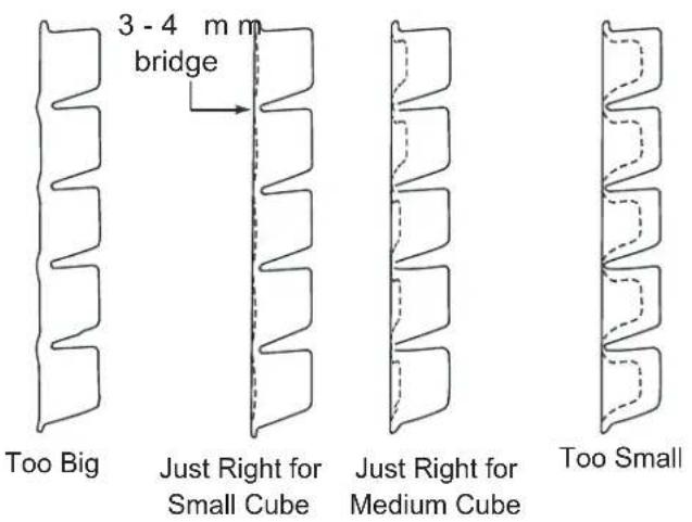
Ice Bridge Thickness Measurement

Ice Thickness Sensor
Water flush setting
The water flush is factory set to the automatic position, suitable for most water conditions. The setting can be changed to one of 5 manual settings or left on automatic.
| Flush setting | 1 - Minimum | 2 - Moderate | 3 - Standard | 4 - Heavy | 5 - Maximum | A - Automatic |
| Water Type | RO water or equivalent | Factory Setting for typical water | High TDS water | Any with conductivity not less than 10 microSiemens/cm |
To set:
1 Switch the machine OFF by holding the Off button in until a number or the letter R shows on the display.
2 Press and release the On button repeatedly until the number on the display corresponds to the desired setting.
3 Press and release the Off switch again to return to the normal control state.
Use and Operation
Once started, the ice machine will automatically make ice until the bin or dispenser is full of ice. When ice level drops, the ice machine will resume making ice.
Caution: Do not place anything on top of the ice machine, including the ice scoop. Debris and moisture from objects on top of the machine can work their way into the cabinet and cause serious damage. Damage caused by foreign material is not covered by warranty.
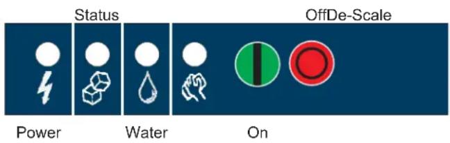
There are four indicator lights at the front of the machine that provide information on the condition of the machine.
Indicator Lights:
- Power
- Status
- Water
- Clean
If the De-Scale light is on, the machine has determined that it may need to be cleaned. Contact an authorized Scotsman service agent and have the machine cleaned, de-scaled and sanitized.
Light indicators & their meanings
| Indicator Lights & Their Meanings | ||||
| Power Status Water De-Scale & Sanitize | ||||
| Steady Green | Normal | Normal – bin full or making ice | - | - |
| Blinking Green | Self Test Failure | Switching on or off - - | ||
| Blinking Red - | Diagnostic shutdown or, if making ice, temperature sensor failure | Lack of water | - | |
| Yellow - - - | Time to de-scale and sanitize | |||
| Blinking Yellow - - - In Cleaning mode | ||||
| Light off No power Switched off Normal Normal | ||||
| All Blinking | Unit remotely locked out – check with leasing company | |||
If the Water light is on, the machine has sensed a lack of water. Check the water supply to the machine. The water may have been shut off or the water filter cartridges need to be changed.
Note: A Component Indicator Light switches ON to indicate that the component is operating.
Note: There are two Curtain Switch lights, SW1 and SW2. A curtain switch light is ON when a curtain is either open or not present.
Switches
There is front access two switches – on and off.
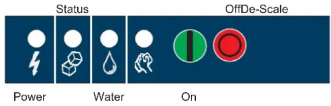
- To switch the machine OFF, push and release the Off button. The machine will shut off at the end of the next cycle.
- To switch the machine ON, push and release the On button. The machine will go through a start up process and then resume ice making.
Control Options
There are two optional, field installed controls that can be on this machine.
• Vari-Smart (KVS) Adjustable ice level control
- Smart-Board (KSB) Advanced Feature control
Adjustable ice level control
When this option is present there is an adjustment post and an additional indicator light to the right of the four indicator lights mentioned above. The ultrasonic ice level control allows the use to control the point that the ice machine will stop making ice before the bin or dispenser is full. Reasons for this include:
• Seasonal changes in ice used
- Planning to sanitize the bin
- Faster turnover for fresher ice
• Certain dispenser applications where maximum ice level is not desired
Use of control
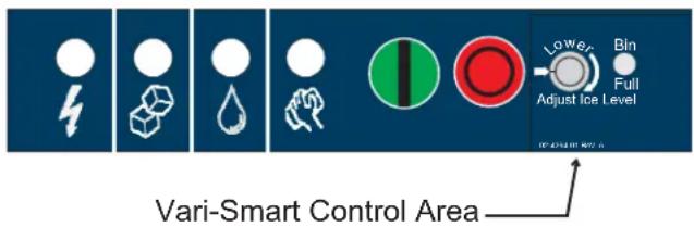
There are several positions the ice level can be set to, including Off (knob and label indicators lined up), where it fills the bin until the standard bin control shuts the machine off. See the kit's instructions for complete details.
Rotate the adjustment post to the desired ice level. The machine will fill up to that level and when it shuts off the indicator light next to the adjustment post will be On.
Note: Ice will build up in the bin or dispenser at an angle, the distances listed above will be from the sensor to the top of the ice directly beneath it.
The actual distance between the highest point of the ice may be closer or further away, depending upon the angle of the ice.
Options and Other Information
SmartBoard
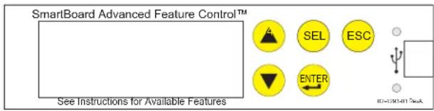
When this option is present there is an additional display panel in the area below the main control board. It is not visible when the front panel is on. The SmartBoard's features include:
- Seven day programmable ice level setting when used with the optional Vari-Smart ice level control
- Recording of machine operation, including cycle time.
• Calculation of average cycle time - Recall of malfunctions with the time they occurred.
Ice
The cuber drops ice in large sections. That ice will break up into random parts as it falls into the bin, but some large sections may remain on top of the ice in the bin. When removing ice, tap the groups of ice with an ice scoop to separate them into smaller units. In a dispenser, this ice will break up into mostly individual cubes as the dispense mechanism moves the ice.
Heat
Air cooled models will generate heat when in operation. That heat is discharged out the back of the cabinet.
Noise
The ice machine will make noise when it is in ice making mode. The compressor, fan motors if air cooled and water pump all produce some sound. It is also normal to hear some cracking just before the harvest cycle begins. In addition, during the harvest cycle the harvest assist solenoid will click twice as it pushes the ice out and returns to its normal position. The ice harvests as a unit or slab, which makes some noise when it impacts the bin or dispenser. These noises are all normal for this machine.
Cleaning, Sanitation and Maintenance
This ice system requires three types of maintenance:
- Remove the build up of mineral scale from the ice machine's water system and sensors.
- Sanitize the ice machine's water system and the ice storage bin or dispenser.
- Clean or replace the air filter and clean the air cooled condenser (air cooled models only).
It is the User's responsibility to keep the ice machine and ice storage bin in a sanitary condition.
Sanitize the ice storage bin as frequently as local health codes require, and every time the ice machine is cleaned and sanitized.
The ice machine's water system should be cleaned and sanitized a minimum of twice per year. This is critical to the proper operation of the ice machine. Contact you local authorized service agent for water system cleaning.
Air cooled condenser filter
- Pull air filter(s) forward from side panel.
- Wash the dust and grease off the filter.
- Return it to its original position.
Do not operate the machine without the filter in place except during cleaning.
Air cooled condenser
If the machine has been operated without a filter the air cooled condenser fins will need to be cleaned.
They are located under the fan blades. The services of a refrigeration technician will be required to clean the condenser.
Exterior Panels
The front and side panels are durable stainless steel. Fingerprints, dust and grease will require cleaning with a good quality stainless steel cleaner.
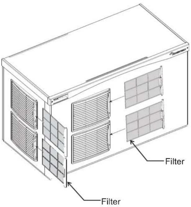
Air Filter Removal
Water filters
If the machine has been connected to water filters, check the cartridges for the date they were replaced or for the pressure on the gauge. Change cartridges if they've been installed more than 6 months or if the pressure drops too much when the ice machine fills with water. Air cooled condenser filter
1 Pull air filters from their louvered mounts.
2 Wash the dust and grease off the filter.
3 Return them to their original positions.
Do not operate the machine without the filter in place except during cleaning.
What to do before calling for service
Reasons the machine might shut itself off:
- Lack of water.
• Freeze cycle takes too long.
• Harvest cycle takes too long.
• High discharge temperature.
• Controller self test failure.
Check the following:
- Has the water supply to the ice machine or building been shut off? If yes, the ice machine will automatically restart within 25 minutes after water begins to flow to it.
- Has power been shut off to the ice machine? If yes, the ice machine will automatically restart when power is restored.
- Has someone shut the water off to a water cooled unit? If yes, the ice machine may need to be manually reset.
- Is the curtain open because some ice is stuck under it? If so, remove the ice and the machine should start in a few minutes.
Note: Curtain can be removed & replaced anytime the machine is in a standby mode or when it is in a freeze cycle. Removal of the curtain during harvest terminates harvest at that point and, if left off, will result in the machine shutting off.
To Manually Reset the machine.
- Push and release the Off button.
- Push and release the On button.
To Shut the Machine Off:
- Push and hold the Off button for 3 seconds or until the machine stops.
Power
Status
Water
De-scale






Sanitize
On
Off
AutoAlert™ Indicator Lights


Technician Section

Manual
Harvest

Clean
Code Display
Control Operation - See Manual
Water Light On - Restore water supply to machine.
De-Scale Light On - Clean and sanitize machine.
Flush Setting - To Change: Depress Off for 3 seconds. Press On to select purge (1-5) setting or A for Automatic.
Test Mode - Depress Off for 3 seconds, then depress Clean for 3 seconds.
Recall Diagnostic Codes - Depress Off for 3 seconds. Press Harvest repeatedly to go from most recent to oldest of 10.
Reset from Code 1, 2, 4 or 8 - Depress Off then Depress On.
Code
Description
F .... Freeze Cycle
F flashes.... Freeze Cycle is Pending
H .... Harvest Cycle
H flashes....Manual Harvest
b....Bin is Full
C .... Clean Cycle
L .... Board Locked
d .... Test Mode
0 .... Off
E .... Self Test Failed
/ flashes.... Max Freeze - Retrying
- . . . . . . . . Max Freeze Time Shut Down
2 flashes.... Max Harvest - Retrying
2....Max Harvest Time Shut Down
3 .... Slow Water Fill
4 .... High Discharge Temp
5 .... Sump Temp Sensor Failure
? ..... Discharge Temp Sensor Failure
8 flashes ... Short Freeze - Retrying
8.... Short Freeze - Thin ice
All 4 Upper Lights Flashing - Unit Remotely
Locked Out - Contact Leasing Company
Component Operation Indicator Lights
02-4189-01 Rev A.


Introduzione
Ghiaccio
Hielo
Sens du débit d'air
Eisdickesensor
Eis
RegisterinstallationsinNorthAmerican,theCaribbean,CentralorSouthAmericabymailingtheyellow registrationformto:
775CorporateWoodsParkway
VernonHills, IL60061
USA
Telephone:847-215-4500Fax:847-913-9844
Registerinstallationsinallotherareasbymailingthecardatthebackofthismanualto:
Phone+39-02-93960208-fax+39-02-93960201
scotsman.europe@frimont.it
SCOTSMAN ICE SYSTEMS
www.scotsman-ice.it
www.scotsman-ice.com
17-3185-03
- SCOTSMAN® ICE SYSTEMS
- INTRODUCTION
- INSTALLATION: PRODUCT SPECIFICATIONS
- SPACE LIMITATIONS
- WARRANTY INFORMATION
- PRODUCT INFORMATION
- EXAMPLE
- OPTIONS
- STANDARD BIN APPLICATIONS - ADAPTER INFORMATION
- OTHER BINS & APPLICATIONS
- WATER
- SCOTSMAN FILTERS
- POTENTIAL FOR AIRBORNE CONTAMINATION
- WATER FLUSH
- UNCRATE AND SET UP
- BIN RECYCLING
- SWITCH BEZEL
- PLUMBING REQUIREMENTS
- WARNING: ALL MODELS REQUIRE CONNECTION TO POTABLE WATER
- ELECTRICAL
- POWER CORD INSTALLATION
- POWER CORD REPLACEMENT
- FINAL CHECK LIST
- AFTER CONNECTIONS
- INITIAL START UP
- TYPICAL ICE MAKING CYCLE TIMES (MINUTES)
- ADJUSTMENTS
- BRIDGE THICKNESS - FOR SERVICE TECH ONLY
- WATER FLUSH SETTING
- USE AND OPERATION
- INDICATOR LIGHTS
- SWITCHES
- CONTROL OPTIONS
- ADJUSTABLE ICE LEVEL CONTROL
- USE OF CONTROL
- OPTIONS AND OTHER INFORMATION
- SMARTBOARD
- ICE
- HEAT
- NOISE
- CLEANING, SANITATION AND MAINTENANCE
- AIR COOLED CONDENSER
- EXTERIOR PANELS
- WATER FILTERS
- WHAT TO DO BEFORE CALLING FOR SERVICE
- CHECK THE FOLLOWING
- TO MANUALLY RESET THE MACHINE
- TO SHUT THE MACHINE OFF
- TECHNICIAN SECTION
- CONTROL OPERATION - SEE MANUAL
- CODE
- DESCRIPTION
- INTRODUZIONE
- GHIACCIO
- HIELO
- EIS
Brand : Scotsman
Model : Prodigy Plus C1848
Category : Ice Maker