TC120ZNT - Heat pump GORENJE - Free user manual and instructions
Find the device manual for free TC120ZNT GORENJE in PDF.

User questions about TC120ZNT GORENJE
0 question about this device. Answer the ones you know or ask your own.
Ask a new question about this device
Download the instructions for your Heat pump in PDF format for free! Find your manual TC120ZNT - GORENJE and take your electronic device back in hand. On this page are published all the documents necessary for the use of your device. TC120ZNT by GORENJE.
USER MANUAL TC120ZNT GORENJE
natural_image
White cylindrical water heater with a digital display and two small connectors at the base (no visible text or symbols)TC 80-120 Z/ZNT
SL Tehnični podatki 3
EN Engineering data 12
DE Technische Daten 21
FR Données techniques 31
TEHNIČNE LASTNOSTI
flowchart
graph TD
    FN1["FN1"] --> A["Weather Icon"]
    FN1 --> B["Weather Icon"]
    FN1 --> C["Weather Icon"]
    FN2["FN2"] --> D["TEMP"]
    FN2 --> E["CLOCK"]
    FN3["FN3"] --> F["MINUS"]
    FN3 --> G["STBY"]
    FN3 --> H["PLUS"]
    FN4["FN4"] --> I["Weather Icon"]
    FN5["FN5"] --> J["Weather Icon"]
    FN6["FN6"] --> K["Weather Icon"]
Table 1: Technical characteristics of the sanitary heat pump
| Type | TC80Z | TC80ZNT | TC100Z | TC100ZNT | TC120Z | TC120ZNT |
| Declared load profile | M | M | M | M | M | M |
| Energy efficiency class 1) | A+ | A+ | A+ | A+ | A+ | A+ |
| Water heating energy efficiency (ηwh) 1) [%] | 111,3 | 111,3 | 110,7 | 110,7 | 111,8 | 111,8 |
| Annual electricity consumption 1) [kWh] | 461 | 461 | 464 | 464 | 459 | 459 |
| Daily electricity consumption 2) [kWh] | 2,205 | 2,205 | 2,225 | 2,225 | 2,240 | 2,240 |
| Thermostat temperature settings | 55 | 55 | 55 | 55 | 55 | 55 |
| Value of "smart" | 0 | 0 | 0 | 0 | 0 | 0 |
| Volume [l] | 78,2 | 78,2 | 97,9 | 97,9 | 117,6 | 117,6 |
| Quantity of mixed water at 40 °C V40 2) [l] | 90 | 90 | 130 | 130 | 142 | 142 |
| Rated pressure [MPa (bar)] | 0.6 (6) | |||||
| Weight / Filled with water [kg] | 58 / 138 | 58 / 138 | 62 / 162 | 62 / 162 | 68 / 188 | 68 / 188 |
| Anti-corrosion protection of tank | Enamelled / MG Anode | |||||
| Insulation thickness [mm] | 40 - 85 | |||||
| Degree of protection | IP24 | |||||
| Max connected load [W] | 2350 | |||||
| Voltage | 230 V / 50 Hz | |||||
| Number and power of heating elements [W] | 2 x 1000 | |||||
| Electricity protection [A] | 16 | |||||
| Adjusted water temperature [°C] | 55 | |||||
| Maximum temperature (HP / el. heater) [°C] | 55 / 75 | |||||
| Legionella control programme [°C] | 70 | |||||
| Temperature range of installation [°C] | 2 to 35 | |||||
| Operation zone – air [°C] | 7 to 35 | -7 to 35 | 7 to 35 | -7 to 35 | 7 to 35 | -7 to 35 |
| Refrigerating agent | R 134a | |||||
| Quantity of coolant [kg] | 0,490 | 0,540 | 0,490 | 0,540 | 0,490 | 0,540 |
| Global Warming Potential | 1430 | 1430 | 1430 | 1430 | 1430 | 1430 |
| Carbon dioxide equivalent [t] | 0,700 | 0,772 | 0,700 | 0,772 | 0,700 | 0,772 |
| *Heating time A15 / W10-55 [h:min] | 4:40 | 4:40 | 5:40 | 5:40 | 6:40 | 6:40 |
| *Energy consumption in the selected cycle of emissions A15 / W10-55 [kWh] | 2,04 | 2,04 | 2,05 | 2,05 | 2,08 | 2,08 |
| *COPDHW in the selected cycle of emissions A15 / W10-55 | 3,10 | 3,10 | 3,10 | 3,10 | 3,10 | 3,10 |
| **Heating time A7 / W10-55 [h:min] | 5:20 | 5:20 | 6:50 | 6:50 | 8:41 | 8:41 |
| **Energy consumption in the selected cycle of emissions A7 / W10-55 [kWh] | 2,45 | 2,45 | 2,35 | 2,35 | 2,51 | 2,51 |
| **COPDHW in the selected cycle of emissions A7 / W10-55 | 2,65 | 2,65 | 2,63 | 2,63 | 2,61 | 2,61 |
| Power in standby mode according to EN16147 [W] | 19 | 19 | 20 | 20 | 27 | 27 |
| Sound power / Sound pressure at 1m [dB(A)] | 51 / 39,5 | |||||
| Air connections [mm/m] | ø125 (☐150x70) / 10 | |||||
| Working Air Flow [m 3/h] | 100-230 | |||||
| Max acceptable pressure drop in the pipeline (volumetric flow rate of air 150 m3/h) [Pa] | 90 | |||||
1) EU Regulation 812/2013; EN16147:2011
2) EN16147:2011
(*) Heating of water to 55 °C at inlet air temperature of 15 °C, 74% humidity and inlet temperature of water of 10 °C; in accordance with the EN16147 standard.
(**) Heating of water to 55 °C at inlet air temperature of 7 °C, 89% humidity and inlet temperature of water of 10 °C; in accordance with the EN16147 standard.
CONNECTION TO WATER SUPPLY MAINS
Water inlet and outlet on the heat pump are marked with colours. Cold water inlet is marked with blue, and warm water outlet is marked with red. The heat pump is designed for connection to indoor water supply mains without using the relief valve if the pressure in the supply mains is lower than 0.6 MPa (6 bar). If the pressure is higher, a relief valve needs to be installed so as to provide that the pressure at the inlet to the hot water tank does not exceed the nominal pressure.
Installing a safety valve is mandatory in order to assure safe operation. The valve prevents an increase of the pressure in the boiler by any more than 0.1 MPa (1 bar) above the rated pressure. The outflow nozzle on the safety valve must have an outlet into the atmosphere. To assure correct operation of the safety valve, the valve must be regularly checked.
When checking the valve, push the lever or unscrew the nut of the valve (depending on the type of the valve) and open the drain from the safety valve. Water must flow from the valve nozzle, showing that the valve operation is faultless. During the heating of water, the water pressure in the hot water tank is increased up to the level preset in the safety valve. Since the system prevents backflow of water into the water supply mains, water may be dripping from the outlet opening on the safety valve. The dripping water may be drained via trap into the drains; the trap is mounted under the safety valve. The outlet pipe, which is mounted under the safety valve, must be directed downwards, in a place with a temperature above freezing.
If the installation does not allow draining of the water from the safety valve into the drains, dripping can be avoided by installing an expansion vessel onto the heat pump inlet pipe. The volume of the expansion vessel must be ca. 3% of the hot water tank volume.
text_image
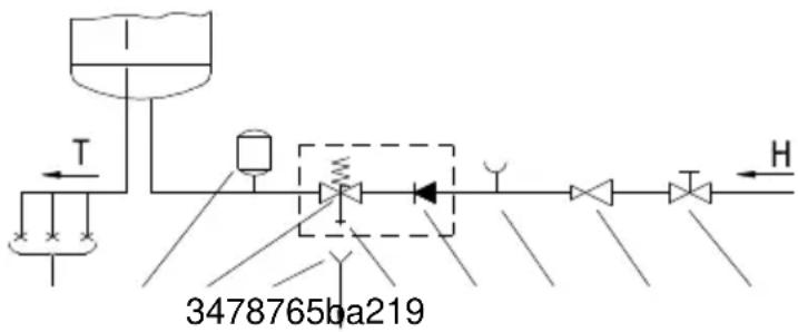
3478765ba219Fig. 1: Closed (pressure) system
flowchart
graph TD
    A["Inlet Pump"] --> B["T"]
    B --> C["Valve"]
    C --> D["Valve"]
    D --> E["Flow Out"]
    C --> F["H"]
    F --> G["Return Flow"]
    style A fill:#f9f,stroke:#333
    style B fill:#ccf,stroke:#333
    style C fill:#cfc,stroke:#333
    style D fill:#fcc,stroke:#333
    style E fill:#cff,stroke:#333
    style F fill:#ffc,stroke:#333
    style G fill:#fcf,stroke:#333
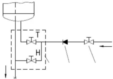
Fig. 2: Open (non-pressure) system
Legend:
1 - Pressure mixer taps
2 - Expansion tank
3 - Safety valve
a - Test valve
b - Non-return valve
4 - Funnel with outlet connection
5 - Checking fitting
6 - Pressure reduction valve
7 - Closing valve
8 - Non-return valve
9 - Low pressure mixer tap
H - Cold water
T - Hot water
PRESSURE LOSS IN CASE OF USING THE PIPELINE SYSTEM
In planning the pipeline system for the inlet and outlet of air to and from the heating pump, the key element is to take into account the aerodynamic character of the fan which also causes the loss of static pressure.
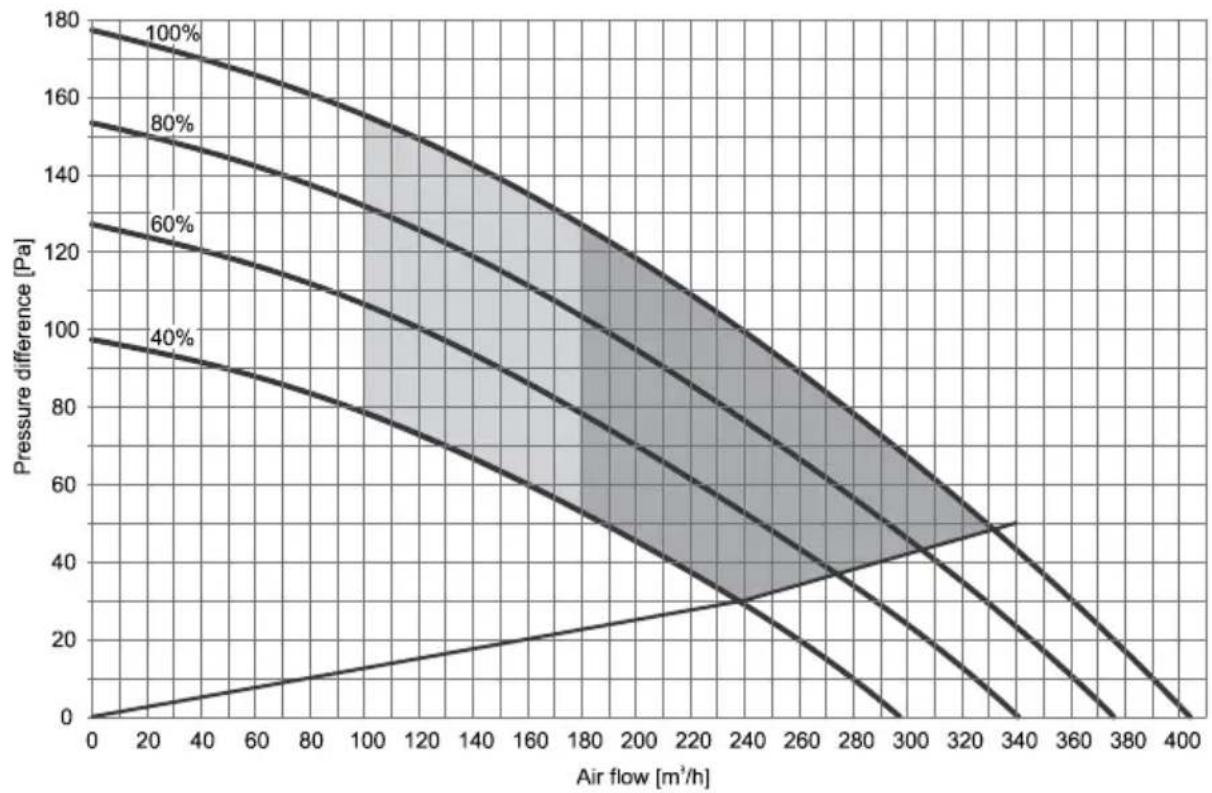
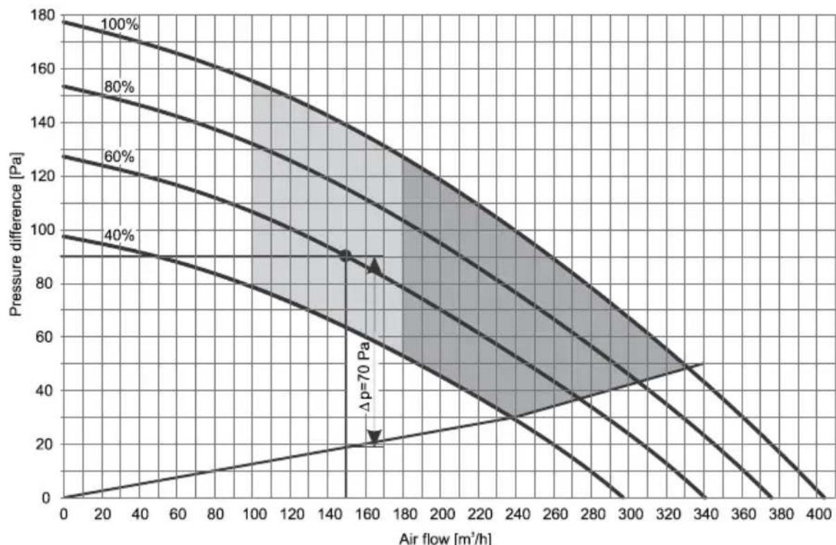
Presentation of the diagram of aerodynamic characteristics for different speeds of the fan
The diagram (Diagram 1) includes aerodynamic characteristics of the operation of the fan. The top line represents the curve of air flow depending on the pressure drop at maximum speed of the fan (100%). The bottom line represents the operation of the fan at minimum speed (40%). The curves between (60%, 80%) represent the aerodynamic characteristics at lowered revolutions of the fan. The bottom line that lies between points (0,0) and (340,50) represents the internal drop of static pressure created by the evaporator alone, without overloading the pipeline system. This pressure drop cannot be eliminated.
area
| Air flow [m³/h] | Pressure difference [Pa] (100%) | Pressure difference [Pa] (80%) | Pressure difference [Pa] (60%) | Pressure difference [Pa] (40%) | | --------------- | -------------------------------- | ------------------------------ | ------------------------------ | ------------------------------ | | 0 | 180 | 155 | 125 | 95 | | 20 | 175 | 150 | 120 | 90 | | 40 | 170 | 145 | 115 | 85 | | 60 | 165 | 140 | 110 | 80 | | 80 | 160 | 135 | 105 | 75 | | 100 | 155 | 130 | 100 | 70 | | 120 | 150 | 125 | 95 | 65 | | 140 | 145 | 120 | 90 | 60 | | 160 | 140 | 115 | 85 | 55 | | 180 | 135 | 110 | 80 | 50 | | 200 | 130 | 105 | 75 | 45 | | 220 | 125 | 100 | 70 | 40 | | 240 | 120 | 95 | 65 | 35 | | 260 | 115 | 90 | 60 | 30 | | 280 | 110 | 85 | 55 | 25 | | 300 | 105 | 80 | 50 | 20 | | 320 | 100 | 75 | 45 | 15 | | 340 | 95 | 70 | 40 | 10 | | 360 | 90 | 65 | 35 | 5 | | 380 | 85 | 60 | 30 | 0 | | 400 | 80 | 55 | 25 | -5 |- Operating area with a normal air flow with respect to the pressure drop and fan setting.
- Area of more efficient use – volumetric flow of air is higher here, which requires a lower pressure drop (channel system with minimum pressure drop). Fan is set to higher speeds.
Diagram 1: Aerodynamic characteristics
Air inlet and outlet pipeline system
When connecting the sanitary heat pump to an existing pipeline system, we use the basic pipe elements that we connect into a pipeline system for air inlet and outlet. The air pipeline should consist of round pipes with an inner diameter of ∅125 mm, or rectangular pipes with a cross section of □150x70 mm.
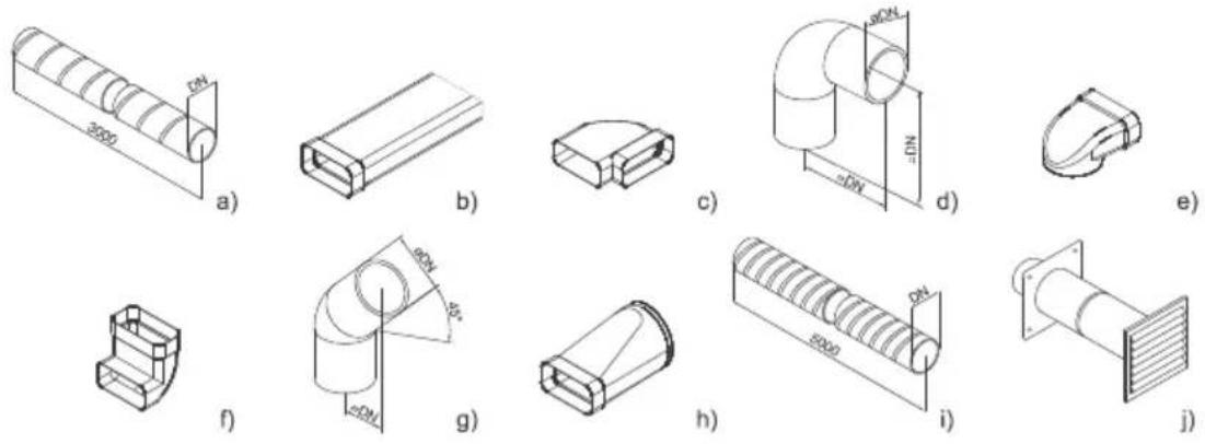
Fig. 3: Schematic demonstration of the basic elements in a pipeline system for inlet and outlet of air
Calculation of pressure drops
The values of total static pressure drop can be calculated by adding up the losses from individual elements built into the air pipeline system and the internal static pressure. The values of static pressure drops of individual elements (static pressure drops of elements relate to the internal diameter ∅125mm or □150x70mm) are shown in Table no. 2.
| Type of element | Value of static pressure loss |
| a.) Spiral ribbed pipe | Diagram 2 |
| b.) Rectangular pipe □150x70 mm | Diagram 2 (according to DN 125) |
| c.) Rectangular elbow - horizontal 90° | 5 Pa |
| d.) Elbow 90° | 4 Pa |
| e.) Angular reducer ∅125 to □150x70 | 5 Pa |
| f.) Rectangular elbow - vertical 90° | 5 Pa |
| g.) Elbow 45° | 3 Pa |
| h.) Reducer ∅125 to □150x70 | 3 Pa |
| i.) Flexible tube | Diagram 2 |
| j.) Air intake grid | 25 Pa |
Table no. 2: Types of elements and corresponding pressure loss values
- Flexible pipe according to DN 125 - Spiral ribbed pipe DN 125
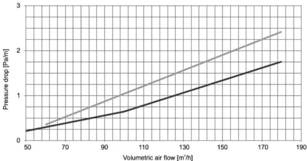
line
| Volumetric air flow [m³/h] | Pressure drop [Pa/m] | | -------------------------- | -------------------- | | 50 | 0.2 | | 70 | 0.4 | | 90 | 0.6 | | 110 | 0.8 | | 130 | 1.0 | | 150 | 1.2 | | 170 | 1.4 | | 185 | 1.6 |Diagram 2: Value of the static pressure drop for selected pipes
| Number of elements | p (Pa) | ΣΔp (Pa) | |
| Rectangular elbow horizontal 90° | 4 | 5 | 20 |
| Flexible tube (DN125) | 13.5 m | 1.85(at 150 m^3/h ) | 25 |
| Air intake grid | 1 | 25 | 25 |
| Total: | 70 |
Table 3: Example of pressure drop calculation
Note: As mentioned above, the total loss of static pressure, which can be calculated by adding up the losses of individual elements built into the pipeline system, may not exceed 95 Pa. If they do, the values of COP start dropping more dramatically.
DETERMINING THE FAN SETTING
When pressure drop is determined, select the mode in which the fan will operate. This determines the speed of the fan. The mode is selected using Diagram no. 1, which shows the aerodynamic characteristics of the fan depending on the air flow and pressure drop in the pipeline*.
Note: *Pressure drop in the pipeline – in diagram 1 this is marked as pressure difference.
Zone of operation of the sanitary heat pump
On diagram 1 there are two zones of operation of the sanitary heat pump among the curves:
- The dark zone represents the area of use with higher efficiency. The volumetric air flow is higher in this zone, which requires a lower pressure drop (channel system version with minimum pressure drop).
- The light zone represents the area of use with lower air flow in relation to the pressure drop and fan setting.
Noise
Like the aerodynamic characteristics rise from the lowest to the highest, the noise increases as well. Between the aerodynamic characteristics 80% and 100% there is a zone with increased noise.
Checking the calculation of pressure drop
Determining the aerodynamic characteristics based on the calculation of pressure drop while taking into account individual elements of the pipeline and air flow is an iteration. Once the aerodynamic characteristic has been determined and set, we must measure the air flow in the pipeline. If the air flow does not correspond to the ventilation system, we select the next higher or lower aerodynamic characteristic that corresponds to the ventilation system.
Selecting the operating point of the fan for the ventilation system
When determining the speed of the fan, we must know the maximum air flow for ventilation and pressure drop caused by the pipeline. In Diagram 1, find the desired air flow and draw a vertical line, then draw a horizontal line at the pressure drop that you have calculated (based on the existing pipeline). Select the fan characteristic curve that lies the closest to the point where the lines cross.
Example of selecting the aerodynamic characteristic
In diagram 3 at air flow of 150 m^3/h draw a vertical line. The pipeline represents 70 Pa of pressure drop, which is added to the below line**. Total pressure drop is thus 90 Pa. Draw a horizontal line at the pressure drop of 90 Pa. The point where the lines meet lies on the curve that corresponds to 60% speed of the fan. This is the standard setting of the fan that has also been preset by the manufacturer.
Note: **Line, represents the internal static pressure drop created by the evaporator.
line
| Air flow [m³/h] | Pressure difference [Pa] (100%) | Pressure difference [Pa] (80%) | Pressure difference [Pa] (60%) | Pressure difference [Pa] (40%) | | --------------- | -------------------------------- | ------------------------------ | ------------------------------ | ------------------------------ | | 0 | 180 | 155 | 130 | 100 | | 20 | 175 | 150 | 125 | 95 | | 40 | 170 | 145 | 120 | 90 | | 60 | 165 | 140 | 115 | 85 | | 80 | 160 | 135 | 110 | 80 | | 100 | 155 | 130 | 105 | 75 | | 120 | 150 | 125 | 100 | 70 | | 140 | 145 | 120 | 95 | 65 | | 160 | 140 | 115 | 90 | 60 | | 180 | 135 | 110 | 85 | 55 | | 200 | 130 | 105 | 80 | 50 | | 220 | 125 | 100 | 75 | 45 | | 240 | 120 | 95 | 70 | 40 | | 260 | 115 | 90 | 65 | 35 | | 280 | 110 | 85 | 60 | 30 | | 300 | 105 | 80 | 55 | 25 | | 320 | 100 | 75 | 50 | 20 | | 340 | 95 | 70 | 45 | 15 | | 360 | 90 | 65 | 40 | 10 | | 380 | 85 | 60 | 35 | 5 | | 400 | 80 | 55 | 30 | 0 |Diagram 3: Example of determining aerodynamic characteristic
SERVICE MENU
Display
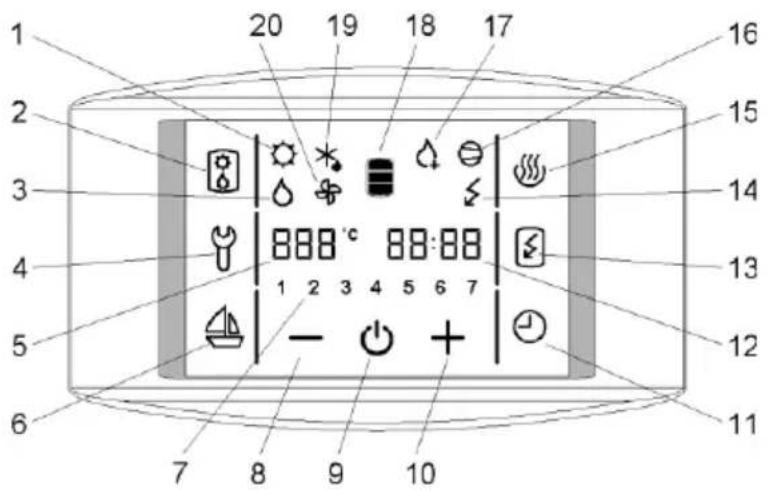
text_image
1 20 19 18 17 3 4 5 6 7 8 9 10 16 15 14 13 12 11Figure no. 4: Control display
1 - Signalisation of the operation of the PV feature *
2 - Activation of ventilation / Activation of the backup mode
3 - Signalization of the backup operation
4 - Indication, overview of operation errors, entrance into the service menu
5 - Display and setup of temperature in °C
6 - Start and setup of the VACATION programme
7 - Day of the week
(1 .. Monday, ..., 7 .. Sunday)
8 - Reducing the value
9 - Heat pump on/off switch
10 - Increasing the value
11 - TIMER start and setup
12 - Time setup and display
13 - Start-up of quick heating "TURBO"
14 - Indicator of the heating element operation
15 - Start-up of heating to the maximum temperature level
16 - Signalization of compressor operation
17 - Signalization of anti-legionella programme operation
18 - Warm water quantity display
19 - Signalization of defrosting
20 - Signalization of fan operation
* function is not used in versions TC-Z, TC-ZNT
Maintenance level access
- By pressing field no. 4, you can activate the maintenance mode (Figure 4).
- A display menu with an inscription "code" in the filed CLOCK appears. Enter the maintenance code (fields FN1, FN2, FN3, FN4, FN5 in FN6 for numbers 1, 2, 3, 4, 5, 6).
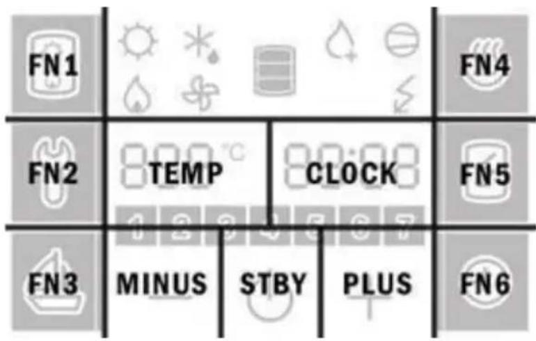
text_image
FN1 FN2 FN3 MINUS STBY CLOCK PLUS FN4 FN5 FN6Figure 5: Fields display
- If you do not press any field for 10 s, the programme returns to the start menu.
- If the code is incorrect, the programme returns to previous operation.
- If the code is correct, the first parameter appears on the display. The number on the right is the serial number of the parameter and the field on the left is intended for its value.
- The first parameter :00 is a version of a software code and serves information purposes only.
- By pressing the right number (Field CLOCK in Figure 5) you proceed to the next parameter.
Installation level (code: 1166)
After the first code entry for the installation level the programme allows access to the following parameters:
:00 programme code
:13 time of operation of the fan - ventilation (5, ... , 180, ON)
:21 fan speed (40, 45, ..., 95, 100)
:39 interval setting for anti-legionella function activation (0, ..., 60)
:45 temperature settings °C or °F
Setting the time of operation of the fan (parameter :13)
- When the parameter (:13) is selected, press either (+) or (−) to set the desired time of operation of the fan (default: 30 minutes). Time up to 30 minutes can be set in 5 min steps, and above 30 minutes in 10 min steps. After the maximum time setting, ON appears, which means that the fan functions constantly until manually switched off.
- When the time of operation of the fan is set, the setting is stored automatically after a short time, or after pressing field no. 4.
Fan speed settings (parameter :21)
- Select the parameter :21 and set the fan speed by pressing (+) or (−) (40% - 100%). See the numerical value settings on the left side in field 5.
- When the fan speed is set, you can save the changes by waiting a few moments or by pressing no. 4.
Anti-legionella function (parameter :39)
- Select the parameter (:39) and set the interval for the anti-legionella function activation (0 to 60 days) by pressing (+) or (−). See the numerical value settings on the left side in field 5. When the interval of the anti-legionella function activation is set, the changes are saved automatically after a few moments, or manually by pressing field no. 4. If the parameter (:39) is set to 0, the anti-legionella function is inactive.
- Factory settings of the anti-legionella function activation: Every 14 days of the heat pump operation, if the water temperature in the previous 2-week period did not exceed 65^ continuously for at least an hour.
- The anti-legionella function works only when the heat pump is switched on. When activated, symbol no. 17 is displayed.
- The anti-legionella function can be activated manually by pressing field no. 15.
- The anti-legionella function can be disabled by switching off the heat pump when pressing field no. 9.
Warning: If heating when the anti-legionella function is activated, the boiler water temperature is 65^ C regardless of the temperature set on the appliance.
Selecting temperature display (parameter: 45)
- When parameter (:45) is selected, press either (+) or (−) to select the manner of temperature display in °C or °F (default value is °C).
- When the desired manner of display is selected, the setting is stored automatically after a short time, or after pressing field no. 4.
TECHNISCHE DATEN
flowchart
graph TD
    FN1["FN1"] --> A["Weather Icon"]
    FN1 --> B["Weather Icon"]
    FN1 --> C["Weather Icon"]
    FN2["FN2"] --> D["TEMP"]
    FN2 --> E["CLOCK"]
    FN3["FN3"] --> F["MINUS"]
    FN3 --> G["STBY"]
    FN3 --> H["PLUS"]
    FN4["FN4"] --> I["Weather Icon"]
    FN5["FN5"] --> J["Weather Icon"]
    FN6["FN6"] --> K["Weather Icon"]