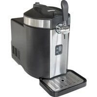
Franzl 48975 - Refrigerator UNOLD - Free user manual and instructions
Find the device manual for free Franzl 48975 UNOLD in PDF.


| Product type | Beer dispenser with integrated cooling |
| Brand | Unold |
| Model | Franzl 48975 |
| Power | 100 watts |
| Voltage | 220-240 V ~ 50 Hz |
| Dimensions (W x D x H) | approx. 27.7 x 46 x 48 cm |
| Weight | approx. 10.9 kg |
| Cable length | approx. 125 cm |
| Housing material | Plastic and stainless steel |
| Color | Black |
| Refrigerant | R600a |
| Climate class | N/SN |
| Cooling temperature range | +2 °C to +12 °C |
| Cooling type | Compressor |
| Keg capacity | 5 litres (universal kegs and self-contained kegs) |
| Pressure system | Integrated CO₂ with 16 g cartridges (food grade) |
| Pressure adjustment | Rotary from - to + |
| Fill level indicator | 5-level LED (keg weight) |
| Drip tray | Removable with grid |
| Included accessories | 2 CO₂ cartridges, universal cap, self-contained keg adapter, cleaning ball, manual |
| Noise level | ≤ 70 dB(A) |
| Maintenance | Regular cleaning of hoses and tray; do not immerse in water |
| Safety | CO₂ cartridges keep out of reach of children; do not expose to +50 °C |
| Warranty | 24 months (household use) |
Frequently Asked Questions - Franzl 48975 UNOLD
User questions about Franzl 48975 UNOLD
0 question about this device. Answer the ones you know or ask your own.
Ask a new question about this device
Download the instructions for your Refrigerator in PDF format for free! Find your manual Franzl 48975 - UNOLD and take your electronic device back in hand. On this page are published all the documents necessary for the use of your device. Franzl 48975 by UNOLD.
USER MANUAL Franzl 48975 UNOLD
natural_image
Modern beer machine with black lid and glass cups on a wooden table, accompanied by a pretzoe and bread roll (no visible text or symbols)Bedienungsanleitung
Instructions for use Model 48975
Foreword....40
Technical data....40
Symbols used in this document....41
For your safety....41
Important information about
the appliance 44
Before first use....44
Insertion and replacement of
CO₂ cartridges....46
Technical data: Co₂ cartridge .....47
General information about beer kegs......48
Connection of a universal 5-litre keg......49
Connecting "fresh kegs" 52
Operation....53
Replacing the beer keg....55
Cleaning and care....56
Overview of spare parts included .....59
Replacing parts....60
Overview of spare parts for the tap unit.....62
Troubleshooting....64
Guarantee Conditions....65
Waste Disposal/Environmental Protection ...65
Service 39
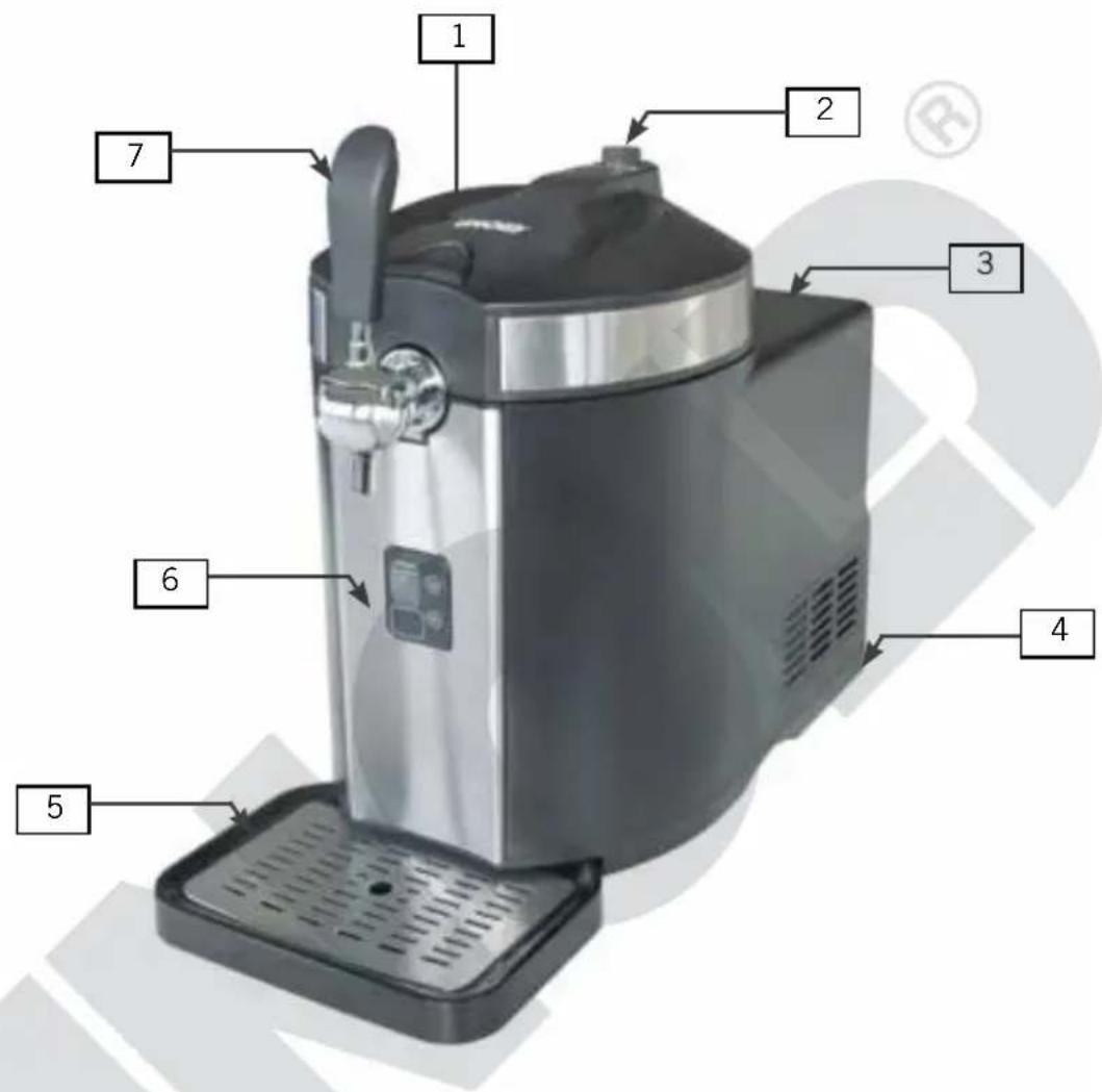
| 1 | Lid with button for opening |
| 2 | CO2 control knob |
| 3 | Hougin |
| 4 | ON /OFF switc |
| 5 | rip tray with grid |
| 6 | Control panel display |
| 7 | Tap |
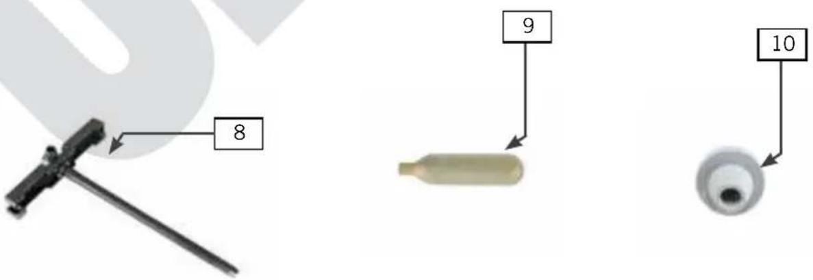
| 8 | Tap tube and tap unit |
| 9 | CO2 cartridge |
| 10 | Beer keg plug |
IHRE NEUE BIERZAPFANLAGE
NL Pagina 89
natural_image
Technical line drawings of industrial machines and components (no text or symbols)Abb. 1 Abb. 2
natural_image
Close-up of a metallic mechanical component with a black arrow pointing to a circular feature (no visible text or symbols)Ablassschraube
natural_image
Close-up of a hand holding a black circular object, partially visible against a dark background (no text or symbols)CO2 -Regler
natural_image
Close-up of a hand pressing down on a black and gray device component (no visible text or symbols)natural_image
Circular metallic object with a central hole, resembling a disc or washer (no text or symbols visible)natural_image
Circular object with concentric rings and a central oval, resembling a stylized eye or lens (no text or symbols)
natural_image
Hand placing a small object into a petri dish with liquid, no visible text or symbolsnatural_image
Close-up of a camera lens aperture (no text or symbols visible)
natural_image
Close-up of a circular mechanical component with a central band and engraved 'PRICE' on the rim (no other text or symbols visible)natural_image
Diagram of a mechanical device mounted on a cylindrical base, with no visible text or symbols.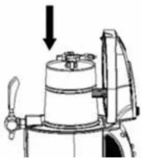
natural_image
Mechanical device diagram showing a cylindrical component with a downward arrow indicating force or direction (no text or symbols present)Abb.5
Abb.4
natural_image
Technical line drawing of a mechanical assembly with no visible text or symbolsnatural_image
Technical line drawing of a mechanical assembly with no visible text or symbolsnatural_image
Technical line drawing of a mechanical component with no visible text or symbolsAbb.9
natural_image
Mechanical assembly diagram showing internal components and a spring (no text or labels)Abb. 11
natural_image
Technical line drawing of a mechanical device with a central component and a valve (no text or symbols)Abb. 12
Copyright UNOLD AG | www.unold.de
natural_image
Mechanical assembly diagram showing a pulley and shaft mechanism (no text or labels)natural_image
Technical line drawing of a mechanical device with no visible text or symbolsAbb. 15
natural_image
Close-up of various mechanical components including a cylindrical connector and multiple ports (no visible text or symbols)natural_image
Two black mechanical components: a coiled spring and a square clamp, displayed on a plain surface (no text or symbols visible)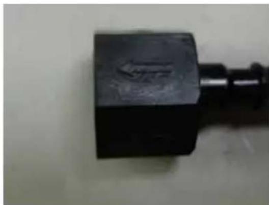
natural_image
Close-up of a black mechanical component with a textured surface and a cylindrical shaft (no visible text or symbols)Copyright UNOLD AG | www.unold.de
natural_image
Hand holding a black and white mechanical valve component with a metallic dial (no visible text or symbols)natural_image
Close-up of a black cylindrical device with a white central component and a coiled spring-like object (no visible text or symbols)natural_image
Person pouring beer from a black water dispenser into a glass, with blurred background signage (no readable text)SERVICE-ADRESSEN
DEUTSCHLAND

Mannheimer Straße 4 68766 Hockenheim
Kundendienst
Telefon +49 (0)62 05/94 18-27
Telefax +49 (0) 62 05/94 18-22
E-Mail service@unold.de
Internet www.unold.de
Thank you for having chosen a quality product from the Unold range. We ask that you read these operating instructions carefully. They will familiarise you with your new beer tap machine (hereinafter “machine” or “appliance”).
Please ensure that the user manual is read and observed by everyone who uses, cleans or maintains the appliance. When handing over the appliance to a new owner, always include the user manual.
If you have any queries that are not answered in this document, or if you encounter technical problems, please contact our Customer Service department or your specialist dealer.
TECHNICAL DATA
Power: 100 W 0–240 Vatt, 220 Hz AC, 5
Dimensions: approx x 46 x 748 W/D/H)m (
Weight: pprox kg . 10.9
Cable length: ox. appr 125 cm
Colour: black
Material: pla teel stic, s
Volume: for 5-litre b eer kegs
Noise level: ≤70 dB(A) noise ≤25 dB(A))
Insulating material: PU insulation, weight 300 ± 5g
Refrigerant: 600a R
Climate classification: N/SN
Temperature range: +2 °C - +12 °C (keg temperature +2 - +5 °C at room temperature +22 - +24 °C)
Features: compressor cooling, integrated and controllable CO
pressure system with exchangeable cartridges, LED fill level indicator, removable drip tray, changing system for the use of 5-litre party kegs and “fresh kegs”
Accessories: 2 CO 2 cartridges, operating instructions
Features, technology, colours, and design are subject to change without notice; errors excepted
CE
SYMBOLS USED IN THIS DOCUMENT
This symbol points to possible dangers that may result in injury or damage to the appliance.
This symbol indicates a potential risk of explosion
FOR YOUR SAFETY
Please read this instruction manual carefully and keep it for future reference.
Persons in household
- This appliance can be used by children aged 8 or above or by individuals with reduced physical, sensory or mental capabilities or a lack of experience and knowledge, if they are supervised or have been instructed in the safe use of the appliance and understand the hazards involved.
- Children must not be allowed to play with the appliance.
- Do not allow children to operate the appliance.
- Children from the age of 8 may be permitted to clean or maintain the appliance, provided they are supervised.
- Keep the appliance and its power cable out of the reach of children under the age of 8.
- Keep alcoholic beverages out of the reach of children!
Safety information for setup and operation of the appliance
-
Switch the appliance on only if it has been set up properly.
-
Make sure there is sufficient room for the appliance. A distance of at least 12 cm must be maintained between the appliance and other objects.
-
Never touch the power plug with wet or moist hands.
-
Connect the appliance to an alternating current source as specified on the type plate.
-
Operate the appliance only on a level and dry work surface.
-
Avoid exposing the appliance to direct sunlight.
-
Never cover the appliance with any type of object during operation.
-
Operate the appliance only in an environment that is protected from the weather, and avoid wind, rain, water droplets, etc.
-
Do not use the appliance in very dusty areas or in the vicinity of flammable substances.
-
Unplug the appliance from the power socket after use and before cleaning – danger of electric shock!
-
Never submerge the appliance or power cable in water or other liquids – danger to life and limb!
-
Remove the beer keg from the appliance only if the keg is completely empty.
-
Do not store any potentially explosive substances, such as spray bottles, in the appliance.
-
The appliance is designed for domestic use only, or for use in similar facilities, e.g.
■ kitchenettes in offices, shops or other workplaces,
- farms,
■ kitchenettes for guests in hotels, motels, hostels,
■ bed and breakfast accommodations and holiday homes.
-
Make sure to route the power cable so that it does not pose a trip hazard.
-
Do not wrap the power cable around the appliance.
-
To prevent damage to the power cable, always grab the power plug to unplug it from the power socket; never pull on the power cable.
-
Make sure that the power socket where the appliance is plugged in is easily accessible, so the plug can be pulled quickly in case of danger.
-
Do not pinch the power cable or route it over edges, to prevent damage to the cable.
-
If possible, do not use extension cords. If this cannot be avoided, please unwind the extension cable completely and observe the power rating of the cable.
-
Regularly check the appliance, the power cable and the plug for wear and damage. If damaged, return the appliance to our customer service department for inspection and repair. Unauthorised repairs can result in serious hazards for the user and will void the warranty.
-
If the power cable is damaged, it must be repaired by the manufacturer or their customer service department, or someone with the necessary technical qualifications, in order to avoid dangers.
- To prevent damage, do not use the appliance with accessories of other manufacturers or brands.
- This appliance does not require water cooling. Therefore: never fill the cooling tank with water – danger of short circuit!
Safety information for handling of CO 2 cartridges
- Use only food-grade CO2 cartridges.
- Remove and dispose of the CO2 cartridge only if it is completely empty, and in accordance with the local regulations.
- Do not use CO2 cartridges at room temperatures above 49 °C. There is a risk of explosion.
- Keep CO2 cartridges away from heat sources (heater, stove, etc.). Never store CO2 cartridges at temperatures above 50 °C. Store the cartridges in a cool and dry location.
- Never throw CO2 cartridges into open flames - danger of explosion!
- Use only 16 g CO2 cartridges, to prevent damage to the appliance. Never use N2O cartridges, e.g. from cream dispensers.
- Keep children and animals away from CO2 cartridges.
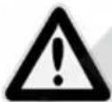
Operate the appliance with dry hands only, otherwise there is danger of electric shock!
Keep CO2 cartridges out of the reach of children - danger of injury.
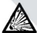
Never use nitrogen cartridges (N2O) in this appliance. Use only CO2 cartridges that are recommended by the manufacturer. Danger of explosion!
The manufacturer will assume no liability in case of incorrect assembly, improper or incorrect use, or damage resulting from unauthorised repairs.
IMPORTANT INFORMATION ABOUT THE APPLIANCE
- This beer tap machine is suitable for household use only. Your beer will be cooled to an agreeable drinking temperature within about 4 hours, depending on the ambient temperature. You can select a temperature in the range from +2 °C to +12 °C.
- We recommend chilling the beer keg in the refrigerator (not the freezer!) for at least 12 hours before connecting it to the beer tap machine. Afterwards, the beer tap machine will keep the beer cold practically indefinitely.
- After connecting a beer keg in the appliance, the beer will keep about 14 days, however only if the appliance is switched on and, in the case of universal beer kegs, a CO2 cartridge is inserted.
BEFORE FIRST USE
- Remove all packaging elements and any transport guards (but not the type plate). Keep packaging elements out of the reach of children – risk of suffocation! Dispose of packaging materials in accordance with local regulations.
- Check whether all accessories listed in this manual are present.
- Inspect the appliance for damage. If there is visible damage, do not operate the appliance; instead, contact our Customer Service department.
- Place the appliance on a level and dry worktop.
- Make sure to maintain a distance of at least 12 cm to other appliances and objects. This will ensure sufficient chilling.
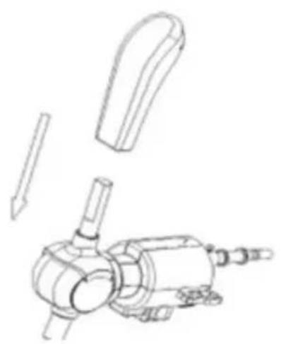
- Place the grip on the tap. Make sure that the two parts are correctly connected (see Fig. 1).
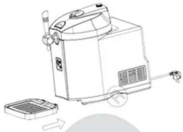
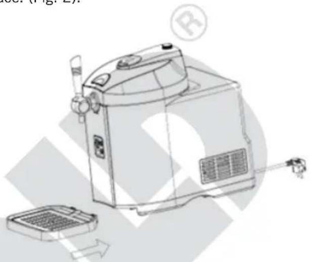
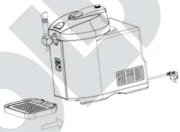
- Set the drip grate in the drip tray. Then push the drip tray into the bottom of the appliance until it is firmly seated. (Fig. 2).
- Plug the appliance into an electrical outlet.
- Caution: Never put water in the opening of the appliance – danger of electric shock! To remove any condensation that has collected, wipe out the inside of the appliance with dry towels.
- The inside of the appliance must empty; objects inside the appliance could damage the weight sensor.
Copyright UNOLD AG | www.unold.de
natural_image
Technical line drawing of a mechanical device with exploded view (no text or symbols)Fig. 1 Fig. 2
natural_image
Line drawing of a portable industrial machine with cooling unit and fan (no text or symbols)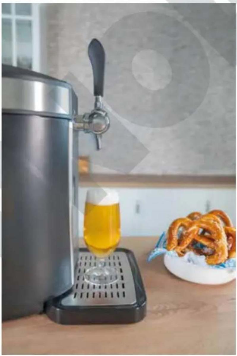
natural_image
Modern beer stand with a glass of yellow liquid being dispensed, accompanied by a plate of pretzels and a forked stand (no text or symbols visible)INSERTION AND REPLACEMENT OF CO 2 CARTRIDGES
Caution: For kegs with an integrated pressure system (“fresh kegs”), this step is not necessary!
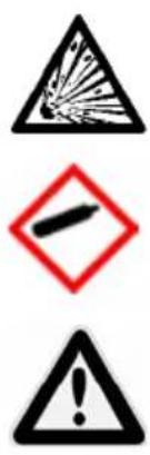
Warning: Never use nitrogen cartridges in this appliance. Use only CO2 cartridges recommended by the manufacturer and observe all of the following information. Incorrect handling of cartridges can cause a risk of explosion! Contains pressurised gas; may explode if heated.
Remove the CO2 cartridge only if it is completely empty. Never use damaged or icy CO2 cartridges.
Store CO2 cartridges in a safe place, out of the reach of children and animals. Risk of injury!
Use only food-grade CO2 cartridges.
natural_image
Close-up of a hand holding a small circular object against a dark background (no text or symbols visible)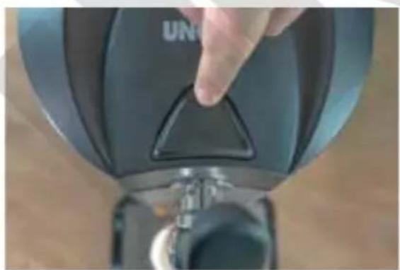
natural_image
Close-up of a hand pressing down on a black industrial device component (no visible text or symbols)- CO2 cartridges should be at room temperature.
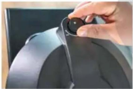
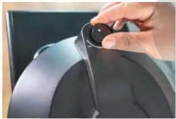
- Turn the CO2 control knob to "-"
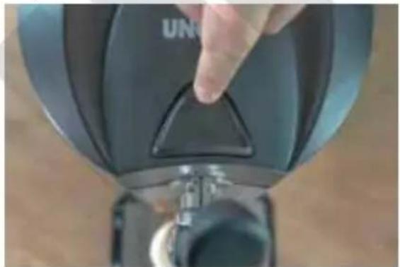
- Open the housing lid by pressing the "Push" button.
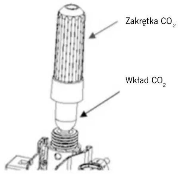
- Pull the CO2 screw cap down, taking care not to kink the hose.
- Loosen the CO2 screw cap by turning it anticlockwise and remove the old CO2 cartridge.
- Now insert the new CO2 cartridge into the holder with the end pointing to the appliance housing and screw the CO2 screw cap clockwise until you hear a clicking sound. The clicking sound indicates that the cartridge cap has been
opened and the CO2 pressurisation system is ready (Fig. 3).
- Push the CO2 screw cap up until it locks firmly into position.
- Always make sure that the cartridge is firmly seated so that no gas can escape.
- Close the lid of the appliance.
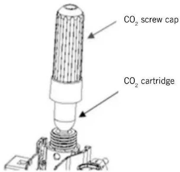
Fig. 3
- Turn the control knob slowly from “-” to “+” and tap some beer to check whether the pressure is sufficient, since different settings are needed depending on the type of beer, chilling, etc.
- Now you can continue tapping beer.
- If you can no longer tap beer although there is still beer in the keg and the pressure control is on “+”, the CO₂ cartridge has to be replaced.
- Never use water to clean a CO2 cartridge; instead, wipe the cartridge off with a dry cloth.
TECHNICAL DATA: CO₂ CARTRIDGE
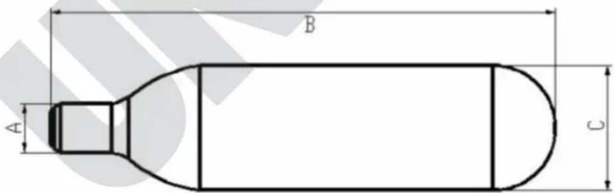
| Net weight 15.5–16.5 g | |
| Volume 20 ml | |
| Gross weight in grams 57-58.6 g | |
| Cartridge weight in grams 42-42.6 g | |
| A ∅ 8.6–8.9 mm | |
| B 88–89 mm | |
| C ∅ 2 mm | 1.7-22 |
| D 1 mm | 10-1 |
| Pressure 60 ( | kgf/cm2) |
| Detonation pressure 450 ( | bar) |
GENERAL INFORMATION ABOUT BEER KEGS
- Read and observe all safety information provided by the manufacturer of the particular beer keg. Bleed the keg according to the instructions on the keg before you connect it.
- Do not shake the keg before connecting it. This will reduce the amount of foam from the tap.
- For optimal results, pre-chill the beer keg for 12 hours in the refrigerator.
- Never store the beer keg in the freezer compartment or freezer chest! Freezing can cause considerable damage to the keg.
- Also, never store the beer keg in direct sunlight.
- Observe the best-before date stamped on the beer keg.
- Never punch a hole in the beer keg, which is under pressure, since injuries could result.
-
Do not use the beer keg if it is damaged. Return damaged beer kegs to the merchant where you purchased the kegs.
-
Before replacing or piercing keg plugs, observe the instructions of the keg manufacturer for bleeding the keg.
- If you use a keg with an integrated pressure cartridge, you do not have to bleed the keg.
- Remove the beer keg from the appliance only if the keg is completely empty.
CONNECTION OF A UNIVERSAL 5-LITRE KEG
Use only universal 5-litre standard kegs and 5-litre kegs with an integrated pressure cartridge in this appliance.
Make sure that the keg is depressurised (tap beer until no more comes out) before removing the piercing tube.
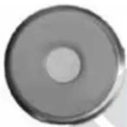
Beer keg plug
Rubber plug
natural_image
Circular metallic object with a central hole, resembling a knob or dial (no text or symbols visible)No tools are needed for this. Remove the cap of the plug, if necessary, and continue as described in “Preparation of the beer keg”.
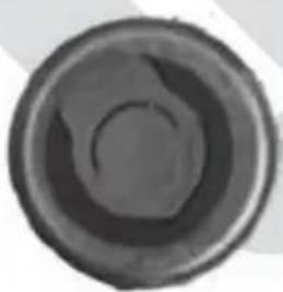
Combination plug
natural_image
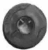
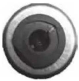
Circular object with a dark, gradient fill, resembling a lens or cap (no text or symbols visible)Combination plugs have a red ring or red cap. The beer keg must first be bled according to the manufacturer's instructions, by raising the tab and slowly turning it. Then the plug can be removed by pulling it quickly upward. This likewise requires no tools. Continue as described in "Preparing the beer keg".
natural_image
Close-up of a dark, textured circular object with a central hole (no visible text or symbols)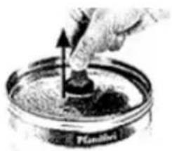
natural_image
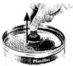
Hand placing a small object into a petri dish with granular contents (no text or symbols visible)Ventilation plug
natural_image
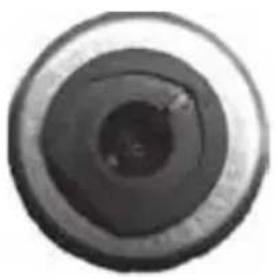
Close-up of a camera lens aperture (no text or symbols visible)These plugs generally have a black cap. The beer keg must first be bled according to the manufacturer's instructions. You will need pliers, however; press the two grips of the pliers together until the plug is severed. Then you can insert the plug that is included. Then continue as described in "Preparing the beer keg".

natural_image
Circular mechanical component with a diagonal stripe and 'PRICE' label (no readable text or symbols beyond the label)Note: For this type of closure, the bottom part of the plug falls into the keg. This has no consequences whatsoever for flavour or health.
Caution: The universal plug that is included can be reused. Remove it from the empty keg by holding the keg firmly with one hand and pulling out the plug forcefully with the other hand (it may be necessary to grip the rubber edge with several fingers).
Proceed with caution when tapping the keg, since there is a risk of injury from sharp-edged parts.
Preparing the beer keg
- First, observe all instructions of the keg manufacturer.
- Make sure that the beer keg you are going to use has been sufficiently pre-chilled.
- Check the ON/OFF switch to make sure the appliance is switched off and the CO2 control knob is on “-”.
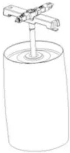
- Align the tap tube of the tap unit against the plug at the upper centre of the keg (Fig. 4). Depending on the type of keg, the closure must first be removed and/or a plug must be replaced; see “Beer keg plug”. Press the tap tube swiftly into the keg until the tap unit has locked into position properly in the keg.
natural_image
Simple line drawing of a cylindrical container with a stand and two vertical supports (no text or symbols)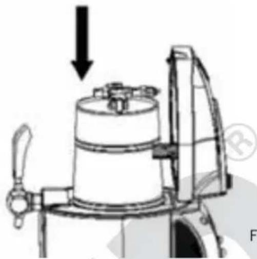
natural_image
Technical line drawing of a mechanical device with a downward arrow indicating force or direction (no text or symbols present)Fig.5
Fig.4
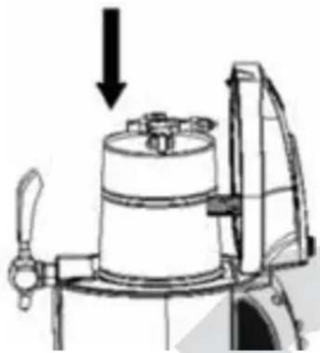
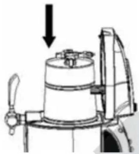
- Press the “Push” button on the appliance lid, open the lid and insert the keg with the tap unit in the cooling tank (Fig. 5). Make sure that the CO₂ hose and the beer hose are not pinched.
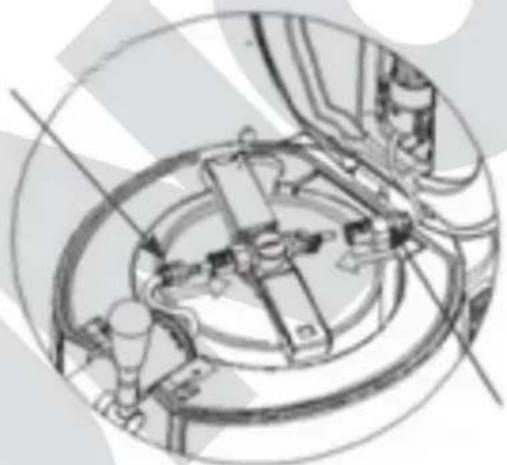
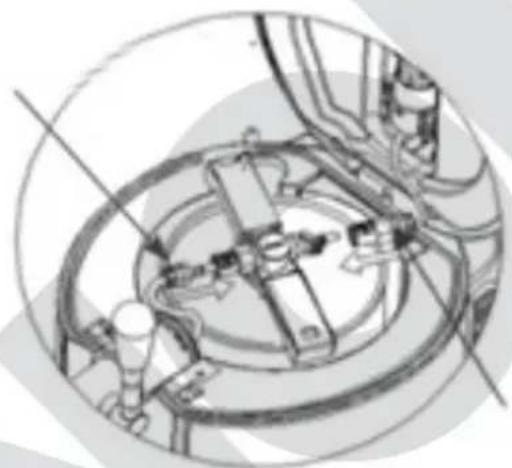
- Make sure that the tap is closed. Then connect the beer hose from the tap to the tap unit (Fig. 6).
Beer hose
natural_image
Technical line drawing of a mechanical assembly with no visible text or symbolsCO2 connection
Fig.6
- Make
sure that a CO2 cartridge is inserted, as described in “Insertion and replacement of CO2
cartridges" on page 46.
- Conn ect the 2 hose to the other connecting element on the tap unit.
-
Close the appliance lid.
-
Plug the appliance into an electrical outlet.
- To switch on the appliance, set the ON/OFF switch on the back to position "I". Position "O" switches the appliance off.
- An acoustic signal will sound and one can hear the cooling compressor.
CONNECTING "FRESH KEGS"

Always turn the CO2 control knob to “-” when using a “fresh keg”!
Since “fresh kegs” are pressurised, exercise caution when connecting them. Always connect the hose to the adapter first, before attaching the adapter to the beer keg.
Never remove the adapter from the keg as long as it is still full and under pressure. The keg must be empty before removing the adapter!
- These kegs already contain CO2 and are therefore pressurised. They do not require pressure control via the CO2 cartridges.
- Make sure that the appliance has been switched off by setting the ON/OFF switch to position "O".
- Remove the adapter from the beer keg and dispose of the keg in accordance with local regulations (Fig. 7a).
- Place the keg in the cooling tank of the a ppliane.
- You must first prepare the tap connection on the beer tap machine. To do so, press the square chrome-coloured button under the hose of the tap assembly inside the appliance. Now you can raise the lid with the beer hose.
- Pull the tap forward a nd pullout the beerhose.
- Now connect the hose directly to the adapter for the “fresh keg” (Fig. 7b). The accessory set supplied includes a pre-prepared adapter with beer hose for fresh kegs.
- Insert the new hose by following the above steps in reverse sequence. To fasten the hose on the tap, pull the tap forward, push the hose onto the tap
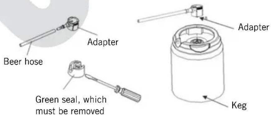
Fig.7
assembly as far as it will go and then release the tap. This is easier to do if you turn the hose back and forth while inserting it.
- Make sure that the tap is closed.
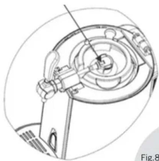
- Now attach the adapter for "fresh kegs", which is connected to the beer tap system, to the keg with sufficient pressure (Fig. 8).
Beer hose connection
natural_image
Technical line drawing of a mechanical assembly with no visible text or symbolsPress in on both sides
natural_image
Technical line drawing of a mechanical component with no visible text or symbolsFig.8 Fig.9
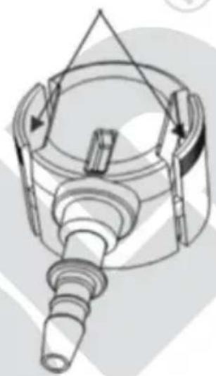
- Caution: When the “fresh keg” is empty, you must remove the adapter, which is reusable. Always press in on both sides of the adapter to release the adapter; otherwise, it could be damaged (see Fig. 9).
- Close the appliance lid.
- Plug the appliance into an electrical outlet.
- To switch on the appliance, set the ON/OFF switch on the back to position "I". Position "O" switches the appliance off.
- An acoustic signal will sound and one can hear the cooling compressor.
OPERATION
Note: Do not switch off the appliance as long as there is a keg containing beer in the appliance. The appliance must be switched on to ensure that the beer is cooled continuously.
Make sure that the beer keg is inserted correctly and that all hoses are properly connected.
Setting the temperature
-
Note: Once the temperature is set, that temperature will be maintained. The temperature is set to +4 °C at the factory.
-
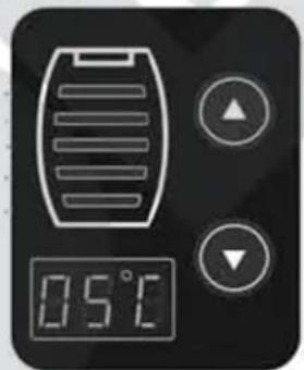
You can increase or decrease the cooling temperature between +2 °C and +12 °C in increments of 1 degree by pressing the ▲ and ▼ buttons on the control panel.
- The current temperature is measured in the cooling tank and shown on the display. The actual temperature of the beer can deviate from this temperature.
- If the appliance is operated at an ambient temperature of about +22 – +24 °C, the beer will be cooled to +2 – +12 °C in about 4 hours; this temperature will be automatically maintained. If the ambient temperature is too high, you must either pre-chill the beer keg or wait a little longer until the beer has reached the desired temperature.
Adjusting the CO2 control
- For universal 5-litre kegs only: The amount of CO2 needed depends on the type of beer, the foaming and the fill level of the keg. You must therefore set the required pressure with the CO2 control knob, by slowly turning it from “-” to “+”. While a keg is being emptied, differing pressure conditions require that this process be carried out regularly.
Tapping beer
- Rinse out the glass with cold water before tapping.
- Hold the beer glass under the tap at an angle, open the tap completely by pulling it forward and let the beer flow into the glass. If the tap is not opened completely, there will be more foam. The beer should flow along the inner side of the glass. This prevents the loss of too much carbon dioxide.
- Raise the glass when the beer foam has reached the edge of the glass. Wait no more than 30 seconds, until the foam has settled somewhat (tip: during this time, do not place the glass directly under the tap, so no beer will drip into it) and then continue tapping by opening and closing the tap until the correct ratio of beer and foam has been achieved.
- B eer should always be served right away.
- Make sure that the tap is closed when you have finished tapping the beer.
- Important: When tapping the first glasses of beer, it is normal that there will be more foam.
- To prevent germs, the beer tap machine must be cleaned regularly. For more information, refer to “Cleaning and care”.
Important information about the CO2 control
Turn the control knob to “-”
■ as long as the beer is being cooled
■ if there is too much foam
■ if tapping of the beer is interrupted
■ when replacing the 2 cartridge
If no beer can be tapped, although there is still beer in the keg, or if there is not enough foam, turn the control to “+” for 5 seconds and then back to “-”.
Fill level indicator
- The fill level indicator shows you how much beer is left in the keg.
- The weight is displayed including the ke g itself.
■ 1st line less than 1,500 g
■ 2nd line 1,500 – 2,500 g
■ 3rd line 2,500 - 3,500g
■ 4th line 3,500 – 4,50 g
■ 5th line more than 4,50 g
natural_image
Digital temperature display showing 0.5°C with control buttons (no text or symbols beyond basic digital icons)REPLACING THE BEER KEG
Remove the tap tube or the "fresh keg" adapter only if the keg is completely empty.
- Setthe CO 2 control knob to the “-” position
- Disconnect the CO2 connection from the piercing unit. Have a glass ready, open the appliance lid and pull the tap down to release the CO2 remaining in the keg. Additional beer foam may escape. Then remove the beer hose by pressing the white release button (fig. 9). This is easier if you press the two connecting elements together a little while doing so.
- Remove the keg from the cooling tank.
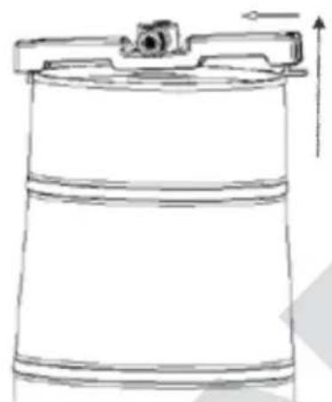
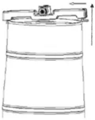
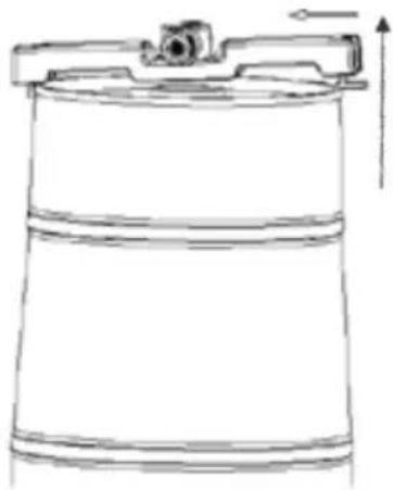
- To release the keg holder of the tap unit from the keg, press the grip of the holder nose up, then pull the keg holder on this side up and away and
Copyright UNOLD AG | www.unold.de
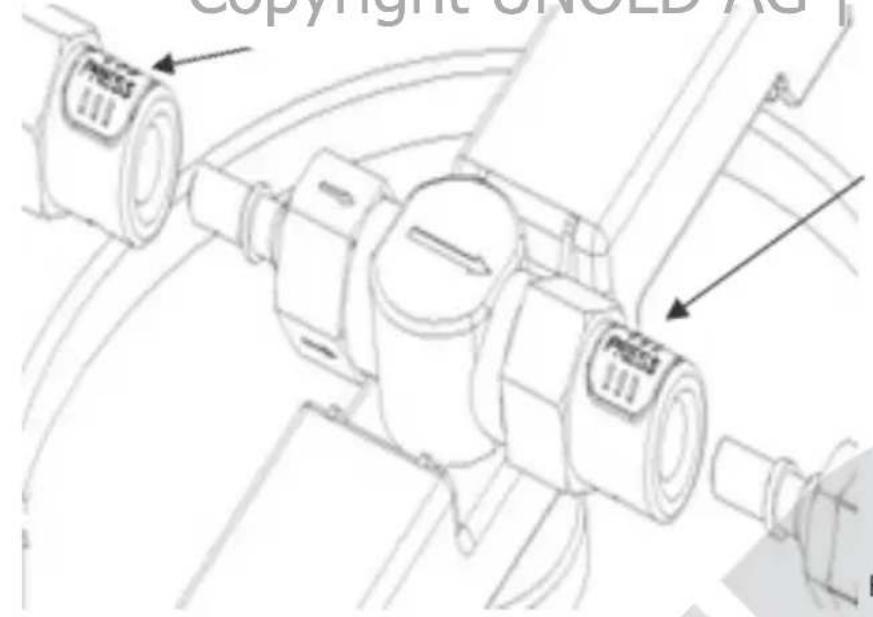
Fig.9
natural_image
Line drawing of a cylindrical container with a lid and upward arrow indicator (no text or symbols)Fig.10
unhook it on the other side. This may require a bit of force. Now the tap unit can be pulled out (Fig. 10).
- Pull the universal plug or the adapter out of the keg. These parts can be reused after they are cleaned.
- Dispose of the empty keg in accordance with local regulations.
CLEANING AND CARE
To prevent germs, the appliance must be cleaned regularly. Regular cleaning will ensure consistent quality of the beer.
Unplug the appliance before cleaning or maintenance. Never immerse the appliance in water!
The appliance must be cleaned thoroughly before first use or after extended non-use.
Clean after every use (not every time beer is tapped, but daily, for example).
General information
The beer tap machine and accessories must be cleaned before first use and at regular intervals during use (e.g. daily before tapping the first beer). The beer tap machine must also be cleaned if it is not used for an extended period.
The beer hose, tap tube and adapter must be cleaned before inserting a new keg. This is necessary to ensure the quality of the tapped beer.
Housing and adapter
- Set the ON/OFF switch to "O" to switch the appliance off.
- Disconnect the plug from the power socket.
- Do not use scouring cleaners, steel wool, metal objects, harsh cleaners or disinfectants, since they can damage the appliance.
- Wipe off the housing thoroughly with a dry cloth.
- Pull the drip tray out of the appliance, empty the tray, and clean the tray and drip grate in warm water with a little washing-up liquid.
- Wipe off the end of the tap thoroughly.
- Remove the adapter only if the keg is empty. Clean the adapter thoroughly with warm washing-up water and allow to dry.
- Never put parts of the tap assembly in the d ishwaher.
Use of the cleaning set – for example, when no beer has been tapped for several days:
- Place a large container under the tap or place the beer tap machine without the drip tray over a sink so the water can flow directly into the sink.
- Keep the tap open at all times when using the tap cleaning ball for cleaning.
- Put some warm, clear water with no additives in a container.
- Fill the cleaning ball with water by squeezing the ball, immersing it in the water and then releasing the ball.
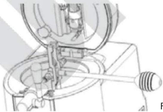
- Connect the tap unit to the beer hose, taking care that the tap tube sticks out of the appliance to the side, as shown in Fig. 11.
natural_image
Mechanical assembly diagram showing a valve mechanism with no visible text or symbolsFig. 11
-
Hold the cleaning ball full of water on the end of the tap tube and pump the water through the tube.
-
Repeat the process at least three times.
-
Caution! Never clean the tap and the parts behind it in the dishwasher! Also, to prevent damage to these parts, do not immerse them in water.
natural_image
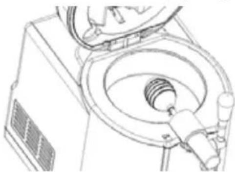
Technical line drawing of a mechanical device with internal components and a valve (no text or symbols)Fig. 12
-
To clean the tap, you can also connect the cleaning ball directly to the beer hose on the tap. Now pump the water through the open tap (Fig. 12).
-
If you use "fresh kegs", also clean this hose
connection using the tap cleaning ball as described when the keg is empty. Do not pull the adapter out of a keg that is not empty, since the pressure could cause beer to emerge.
Storage of the appliance
- Allow the beer tap machine to dry completely before putting it away.
- Note: The appliance operates with a compressor. As a result, condensation water can collect inside the appliance. After switching off the appliance, it should therefore remain unpacked for at least two days, to allow the condensation water to evaporate.
- If the beer tap machine is not to be used for an extended period, it should preferably be packed in the original box in a protected, dry area that is free of dust.
OVERVIEW OF SPARE PARTS INCLUDED
| No. | Art-No. Name | Quantity Mounting | location | Illustration | |
| 1 | 4897523 Seal | 2 | CO2 cartridge holder tap spike |  | |
| 2 | 4897591 | Tap tube cartridge | 2 | CO2 cartridge holder |  |
| 3 | 4897532 Beer | hose 1 T | ap |  | |
| 4 | 4897524 Tube | seal 3 ap tu | T be |  | |
| 5 | 4897521 | Beer keg plug | 2 | Standard keg |  |
| 6 | 4897585 | Adapter | 2 | “Fresh keg” |  |
| 7 | CO2 cartridge | 3 | CO2 cartridge holder |  | |
| 8 | 897580 | Tap cleaning ball | 1 |  |
REPLACING PARTS
Replacing the tap spike and seal
The tap spike for cartridges and the seal can become worn over time or be damaged from improper handling. In this case, these parts must be replaced as follows:
- Remove the old seal, for example with a small screwdriver, a toothpick or similar pointed object (Fig. 13). Make sure that the small parts do not fall into the lid.
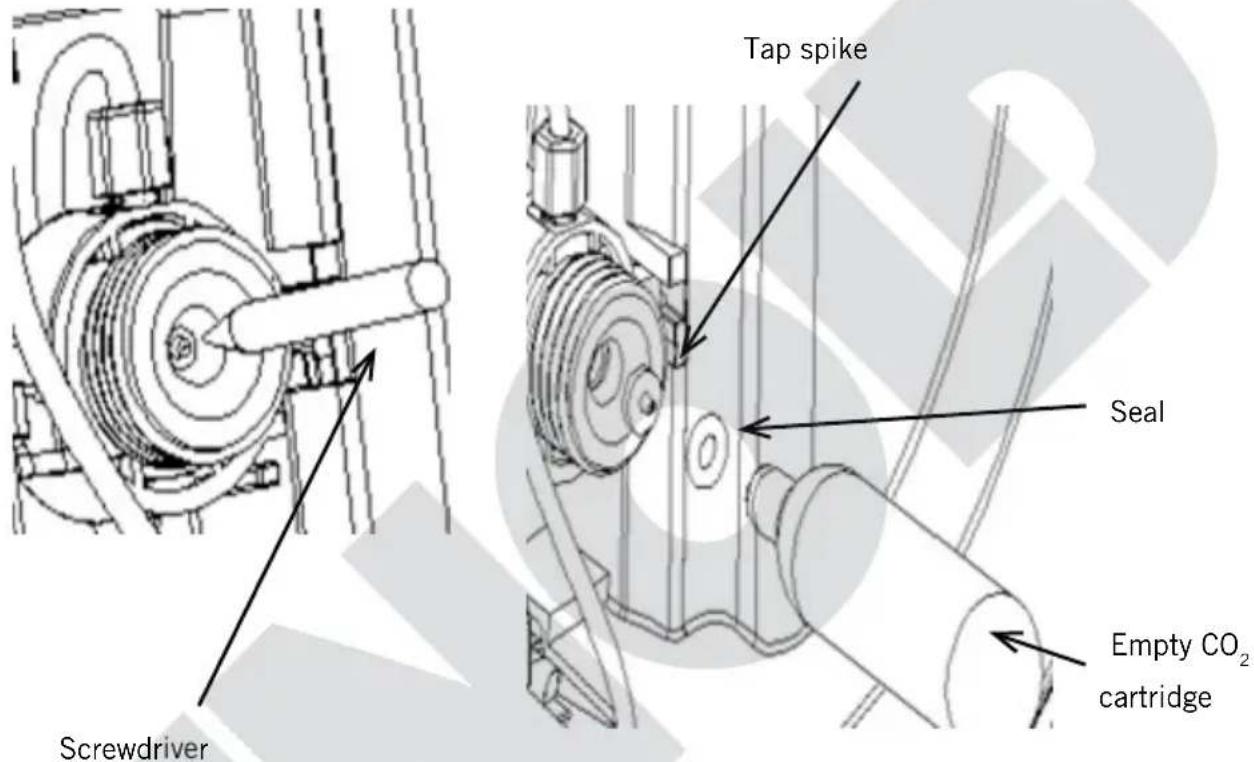
Fig. 13
Fig. 14
- Remove the tap spike. Important – work slowly, to prevent damage or accidental removal of other parts.
- Insert the new tap spike, with the pointed end facing the CO2 cartridge.
- Check whether the seal is still intact and replace it, if necessary. Re-insert the seal.
Press the new seal into position. Use an empty CO2 cartridge to set the seal properly (Fig. 14).
Replacing the beer hose
- If the beer hose is damaged, it must be replaced in order to continue tapping beer.
natural_image
Technical line drawing of a mechanical device with no visible text or symbolsFig. 15
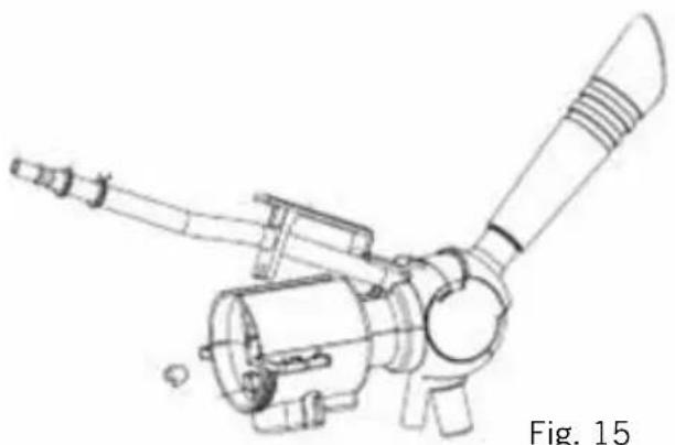
- Press the square chrome-coloured button under the hose of the tap assembly inside the appliance. Now you can raise the lid with the beer hose (Fig. 15).
- Pull the tap forward and pull out the beer hose.
- Open the hose clamp at the other end of the hose. To do so, press the two eyelets together. Now you can remove the hose
clamp from the hose. Pull the black adapter element off of the connection on the valve of the tap unit.
- Insert the new hose by following the above steps in reverse sequence. To fasten the hose on the tap, pull the tap forward, push the hose onto the tap assembly as far as it will go and then release the tap. This is easier to do if you turn the hose back and forth while inserting it.
Replacing the tube seal on the tap spike of the tap unit
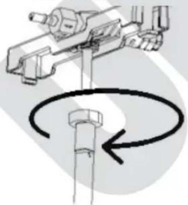
- Replace the tube seal as soon as it starts to leak.
- Twist off the taptube.
- Remove the tube seal from the line.
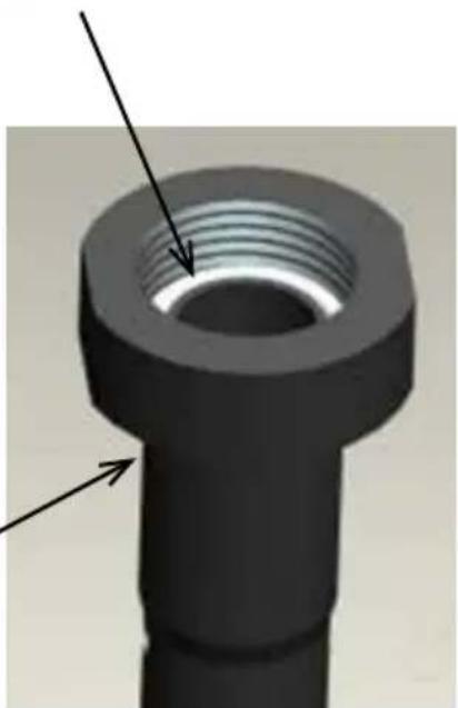
- Insert the new tube seal and tighten the tap tube (Fig. 16) so that no liquid can escape.
natural_image
Technical line drawing of a mechanical assembly with a rotating shaft and bolt (no text or symbols)Tap tube Fig. 16
Seal
natural_image
3D rendered mechanical component with threaded end and flange, showing no text or symbolsOVERVIEW OF SPARE PARTS FOR THE TAP UNIT
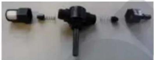
Caution: The tap unit consist of small parts. Keep this component and all of its single parts out of the reach of children, animals and helpless persons – danger of suffocation from swallowing small parts!
- Always make sure to connect the correct hoses and threads, since otherwise the components could be damaged. Never remove other parts, to prevent damage to the appliance.
- The tap unit, to which the tap tube is connected, consists of two sides. One side is for connecting to the CO2 cartridge, the other side is connected to the
natural_image
Close-up of various black plastic components and connectors on a plain surface (no text or symbols visible)beer hose, to allow the beer to flow from the tap.
-
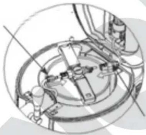
The CO2 side consists of coarse threads and a thin spring with a small ram and is connected to the CO2 connection. There are four small arrows stamped on the threads which indicate the direction of flow of the CO2 .
-
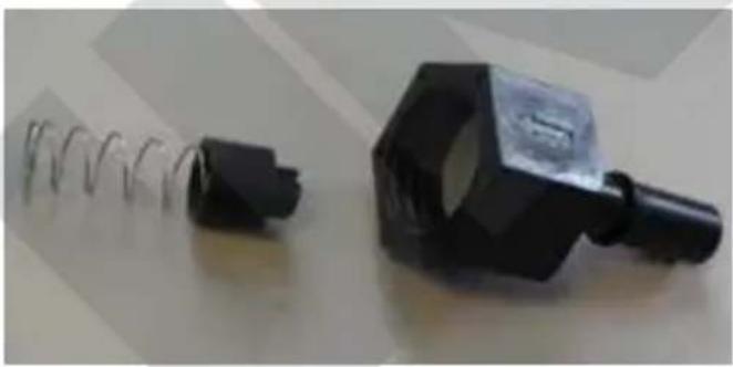
There is also an arrow stamped on the middle part of the tap unit, indicating the direction of flow; this arrow must point in the direction of the beer hose.
natural_image
Two black mechanical components: a coiled spring and a clamped clamp, placed on a plain surface (no text or symbols visible)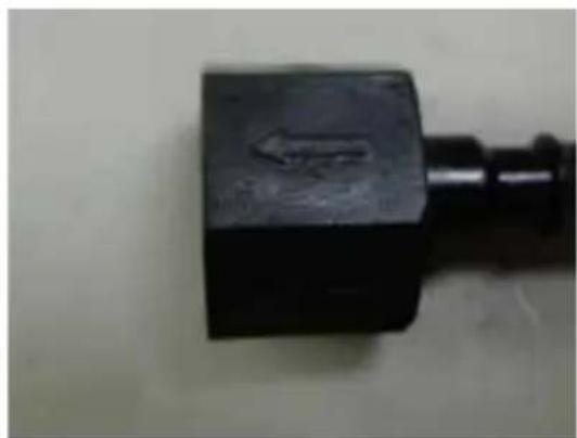
natural_image
Close-up of a black mechanical component with a small protrusion on the right end (no visible text or symbols)
natural_image
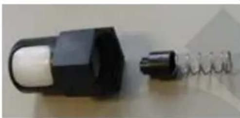
Hand holding a black mechanical pressure regulator with threaded ports and a central dial (no visible text or symbols)- On the other side of the tap unit, which leads in the direction of the beer hose, there is a somewhat heavier spring. When correctly assembled, this
natural_image
Close-up of a black plastic component with a white cylindrical body, next to a coiled spring (no text or symbols visible)spring is held in the right position; alternatively, you can press it carefully with your finger.
- To remove this connection, it must be pushed slightly to the middle in the direction of the tap tube, making it easier to press the release button.
TROUBLESHOOTING
If the following suggestions do not help you to solve the problem, contact our customer service department.
Problem Cause Remedy
| No beer emerges from the tap | CO2control closed Turn control knob to “+” | |
| No beer keg, or keg is empty | I keg in plian | |
| Beer hose or CO2connection not connected | C parts tly | |
| CO2cartridg empty | ert a d 2 | |
| Too much foam emerges from the tap | Un e tappim | O I information in se on on “Operation” for correct tapping of beer |
| Beer hig | Ideal temperature is 3-5 °C | |
| eg was shaken sertion | Allow keg to rest so the foam inside can settle | |
| Exc pressure in the beer keg | Set the CO2control knob to “-” to reduce the pressure | |
| g is almost empty Insert a new beer keg | ||
| Beer o Insufficient pressure | Increase the pressure using the control knob, or replace the CO2cartridge | |
| Hoses are defective Check all hoses for leaks and replace, if necessary. | ||
| CO2emerges too fast after inserting a new cartridge | CO2control knob not set to “-” Set control knob to “-” | |
| Seal on the CO2control is damagedCartridge tap tube is defective | Replace the sealReplace the tap tube | |
GUARANTEE CONDITIONS
We grant a 24 months guarantee, and in case of commercial use a 12 months guarantee, starting from the date of purchase for any damage demonstrably due to manufacturing defects and when the appliance has been used according to its intended use. Within the warranty period we will remedy defective materials or workmanship through repair or replacement, at our option. Our warranty terms apply only to appliances sold in Germany and Austria. For other countries, please contact the responsible importer. In the event of a claim for remedy of defects, please send the appliance to our after sales service, properly packaged, together with a copy of the automatically generated sales receipt, which must show the date of purchase, and a description of the defect. You can print out a return receipt on our website https://unold.de/pages/rucksendungen. (only for entries from Germany and Austria). The warranty does not cover damage from normal wear, improper handling and failure to comply with the maintenance and care instructions. The warranty is void if repairs or modifications are made to the appliance by third parties. Any claims of the end consumer vis-à-vis the retailer are not limited by this warranty.
WASTE DISPOSAL / ENVIRONMENTAL PROTECTION
Our appliances are produced on a highquality level for a long lifetime. Regular maintenance and expert repairs by our after-sales service can extend the useful life of the appliance. If an appliance is defective and repair is not possible, we ask you to follow the following instructions for disposal. Do not dispose this appliance together with your standard household waste. There is a legal requirement to dispose of waste electrical and electronic equipment (WEEE) as well as batteries and accumulators separately from household waste. You can recognise this waste equipment by the crossed-out wheeled bin symbol (WEEE symbol).
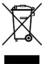
Please bring this product to an approved collection point for recycling of electric and electronic products. By separate collection and disposal of waste products you help to protect natural resources and ensure, that the product is disposed in an adequate way to protect health and environment.
Dispose of CO2 cartridges in accordance with local regulations.
The instruction booklet is also available for download: www.unold.de
Refrigerant: R600a
NOTICE D'UTILISATION MODÈLE 48975
AVANT-PROPOS
natural_image
Technical line drawing of a mechanical device with exploded view (no text or symbols)Fig. 1 Fig. 2
natural_image
Line drawing of a portable industrial machine with cooling fan and control panel (no text or symbols)natural_image
Close-up of a hand adjusting a black spherical device with a small circular component, mounted on a stand (no visible text or symbols)natural_image
Circular metallic object with a central hole, resembling a knob or dial (no text or symbols visible)natural_image
Circular object with a dark center and lighter outer ring, resembling a mechanical or architectural component (no text or symbols visible)natural_image
Hand placing a small object into a petri dish with liquid, no visible text or symbolsnatural_image
Close-up of a camera lens aperture (no text or symbols visible)natural_image
Circular mechanical component with a diagonal stripe, no visible text or symbolsnatural_image
Simple line drawing of a cylindrical container with a vertical rod inserted into it, containing three cross-shaped objects (no text or symbols)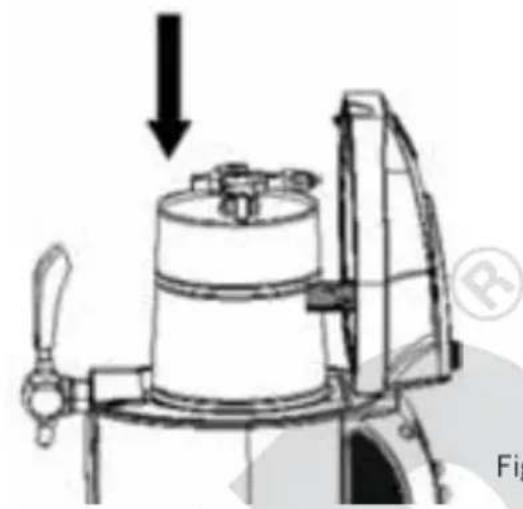
natural_image
Technical line drawing of a mechanical device with a downward arrow and base plate (no text or symbols)Fig.5
Fig.4
natural_image
Mechanical assembly diagram showing gears and shafts in a circular frame (no text or labels)Raccordement CO2
Fig.6
natural_image
Technical line drawing of a mechanical component with no visible text or symbolsnatural_image
Digital temperature display showing 0.5°C with control buttons (no text or symbols beyond basic digital numerals)REEMPLACER LE FÛT DE BIÈRE
Fig.9
natural_image
Line drawing of a cylindrical container with a side-mounted lid and upward arrow indicator (no text or symbols)Fig.10
natural_image
Mechanical assembly diagram showing a valve mechanism with no visible text or symbolsFig. 11
natural_image
Technical line drawing of a mechanical device with a central cylindrical component and surrounding components (no text or symbols)Fig. 12
natural_image
Technical line drawing of a mechanical device with no visible text or symbolsFig. 15
natural_image
Close-up of several black plastic mechanical components with connectors, arranged on a plain surface (no text or symbols visible)natural_image
Close-up of a black mechanical component with coiled spring and handle, no visible text or symbols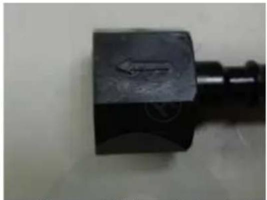
natural_image
Close-up of a black mechanical component with a circular mark and arrow symbol (no readable text or symbols)natural_image
Hand holding a black mechanical pressure regulator with threaded ports and a central dial (no visible text or symbols)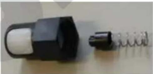
natural_image
Close-up of a black plastic mechanical component with a coiled spring attached (no visible text or symbols)SOLUTIONNER LES ERREURS
CONDITIONS DE GARANTIE
natural_image
Technical line drawing of a mechanical device with no visible text or symbolsafb. 1 afb. 2

natural_image
Line drawing of a portable appliance with a side panel and fan, showing no text or symbolsnatural_image
Close-up of a hand adjusting a black circular component on a dark surface (no text or symbols visible)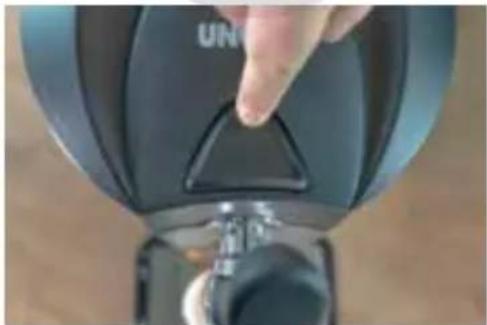
natural_image
Close-up of a hand pressing a black triangular button on a device (no visible text or symbols)natural_image
Circular metallic object with a central hole, resembling a knob or dial (no text or symbols visible)natural_image
Circular object with a central oval shape, resembling a lens or cap (no text or symbols visible)natural_image
Hand using a tool to press or sample material in a petri dish (no visible text or symbols)Ontluchtingsstop
natural_image
Close-up of a camera lens aperture (no text or symbols visible)natural_image
Close-up of a circular mechanical component with a central band (no visible text or symbols)natural_image
Simple line drawing of a cylindrical container with a stand and two vertical rods above it, no text or symbols present.afb.4
natural_image
Technical line drawing of a mechanical device with a downward arrow indicating force or direction (no text or symbols present)afb.5
Bierslang
natural_image
Technical line drawing of a mechanical assembly with no visible text or symbolsnatural_image
Technical line drawing of a mechanical component with no visible text or symbolsnatural_image
Technical line drawing of a mechanical component with no visible text or symbolsnatural_image
Technical line drawing of a mechanical device with no visible text or symbolsafb.9
Copyright UNOLD AG | www.unold.de
natural_image
Mechanical assembly diagram showing internal components and a threaded shaft (no text or labels)afb.11
natural_image
Technical line drawing of a mechanical device with a central circular component and internal components (no text or symbols)natural_image
Mechanical assembly diagram showing a rotating shaft and housing mechanism (no text or labels)natural_image
Technical line drawing of a mechanical device with no visible text or symbolsBierslang vervangen
natural_image
Technical line drawing of a mechanical assembly with no visible text or symbolsnatural_image
3D rendered mechanical component with threaded end and arrow annotations (no text or symbols)natural_image
Close-up of various electronic components including a plug, connector, and socket (no visible text or symbols)natural_image
Close-up of two mechanical components: a black plastic clamp and a coiled spring, both on a plain surface (no text or symbols visible)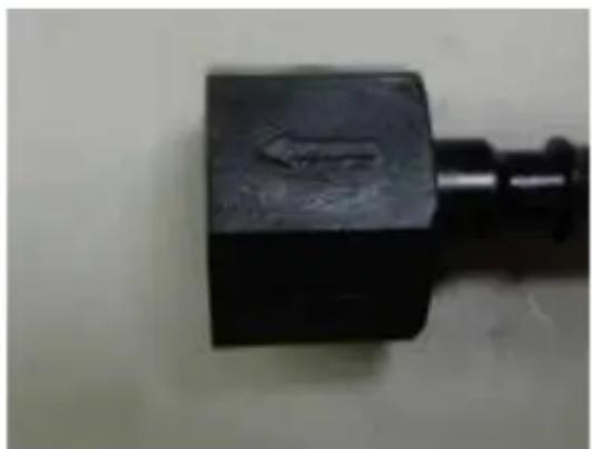
natural_image
Close-up of a black mechanical component with a small protrusion (no visible text or symbols)natural_image
Hand holding a black mechanical pressure regulator with threaded end (no visible text or symbols)natural_image
Close-up of a black plastic component with a white circular body and a coiled spring attached (no text or symbols visible)STORINGEN VERHELPEN
natural_image
Technical line drawing of a mechanical device with exploded view (no text or symbols)ilustr. 1
natural_image
Line drawing of a portable industrial machine with cooling unit and side panel (no text or symbols)ilustr. 2
natural_image
Close-up of a hand holding a small black circular object against a dark background (no text or symbols visible)natural_image
Close-up of a hand pressing a black triangular button on a device (no visible text or symbols)Copyright UNOLD AG | www.unold.de
natural_image
Circular metallic object with a central hole, resembling a knob or dial (no text or symbols visible)natural_image
Circular object with a dark center and lighter outer ring, resembling a lens or cap (no text or symbols visible)natural_image
Hand placing a small object into a petri dish with an arrow indicating upward motion (no text or symbols)natural_image
Close-up of a camera lens aperture (no text or symbols visible)natural_image
Circular object with a diagonal band and 'FROCH' label, no readable text or symbols beyond the label.natural_image
Simple line drawing of a cylindrical container with a vertical rod inserted into it, containing liquid (no text or symbols)ilustr.4
natural_image
Technical line drawing of a mechanical device with a downward arrow indicating force or direction (no text or symbols present)ilustr.5
Wąż piwa
natural_image
Technical line drawing of a mechanical assembly with no visible text or symbolsnatural_image
Technical line drawing of a mechanical assembly with no visible text or symbolsnatural_image
Technical line drawing of a mechanical component with no visible text or symbolsilustr.8 str.9
natural_image
Technical line drawing of a mechanical device with no visible text or symbolsilustr.9
natural_image
Line drawing of a cylindrical container with a side-mounted lid and upward arrow indicator (no text or symbols)ilustr.10
natural_image
Mechanical assembly diagram showing internal components and a threaded shaft (no text or labels)ilustr. 11
natural_image
Technical line drawing of a mechanical device with a central bulb and internal components (no text or symbols)ilustr. 12
- W
przypadku sto-
sowania beczek
świeżego pro-
duktu należy
przeptukać
również to
przyłącze węża w
Copyright UNOLD AG | www.unold.de
natural_image
Mechanical assembly diagram showing a pulley and shaft mechanism (no text or labels)natural_image
Technical line drawing of a mechanical device with no visible text or symbolsnatural_image
Close-up of various mechanical components including a cylindrical connector and threaded fastener (no visible text or symbols)natural_image
Close-up of two mechanical components: a coiled spring and a black clamp-like device (no visible text or symbols)
natural_image
Close-up of a black mechanical component with a small arrow symbol on its side (no text or labels visible)Copyright UNOLD AG | www.unold.de
natural_image
Hand holding a black and white industrial pressure regulator valve (no visible text or symbols)natural_image
Close-up of a black cylindrical device with a white circular top and a coiled spring attached (no text or symbols visible)USUWANIE USTEREK

- Bedienungsanleitung
- Instructions for use Model 48975
- IHRE NEUE BIERZAPFANLAGE
- Copyright UNOLD AG | www.unold.de
- SERVICE-ADRESSEN
- DEUTSCHLAND
- TECHNICAL DATA
- SYMBOLS USED IN THIS DOCUMENT
- FOR YOUR SAFETY
- Please read this instruction manual carefully and keep it for future reference.
- Persons in household
- Safety information for setup and operation of the appliance
- Safety information for handling of CO 2 cartridges
- IMPORTANT INFORMATION ABOUT THE APPLIANCE
- BEFORE FIRST USE
- INSERTION AND REPLACEMENT OF CO 2 CARTRIDGES
- GENERAL INFORMATION ABOUT BEER KEGS
- CONNECTION OF A UNIVERSAL 5-LITRE KEG
- Beer keg plug
- Rubber plug
- Combination plug
- Ventilation plug
- Preparing the beer keg
- CONNECTING "FRESH KEGS"
- OPERATION
- Note: Do not switch off the appliance as long as there is a keg containing beer in the appliance. The appliance must be switched on to ensure that the beer is cooled continuously.
- Setting the temperature
- Adjusting the CO2 control
- Tapping beer
- Important information about the CO2 control
- Fill level indicator
- REPLACING THE BEER KEG
- Remove the tap tube or the "fresh keg" adapter only if the keg is completely empty.
- CLEANING AND CARE
- General information
- Housing and adapter
- Use of the cleaning set – for example, when no beer has been tapped for several days:
- Storage of the appliance
- REPLACING PARTS
- Replacing the tap spike and seal
- Replacing the beer hose
- Replacing the tube seal on the tap spike of the tap unit
- OVERVIEW OF SPARE PARTS FOR THE TAP UNIT
- TROUBLESHOOTING
- GUARANTEE CONDITIONS
- WASTE DISPOSAL / ENVIRONMENTAL PROTECTION
- NOTICE D'UTILISATION MODÈLE 48975
- AVANT-PROPOS
- REEMPLACER LE FÛT DE BIÈRE
- SOLUTIONNER LES ERREURS
- CONDITIONS DE GARANTIE
- Ontluchtingsstop
- Bierslang vervangen
- STORINGEN VERHELPEN
- USUWANIE USTEREK
Brand : UNOLD
Model : Franzl 48975
Category : Refrigerator