
VMF308 - Wall mount SANUS - Free user manual and instructions
Find the device manual for free VMF308 SANUS in PDF.

User questions about VMF308 SANUS
0 question about this device. Answer the ones you know or ask your own.
Ask a new question about this device
Download the instructions for your Wall mount in PDF format for free! Find your manual VMF308 - SANUS and take your electronic device back in hand. On this page are published all the documents necessary for the use of your device. VMF308 by SANUS.
USER MANUAL VMF308 SANUS
natural_image
3D diagram of a wooden stud with vertical supports and a curved cutout (no text or symbols)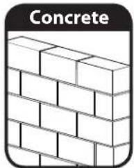
natural_image
Illustration of a brick wall with no text or symbols, labeled 'Concrete' at the top (no other text or symbols)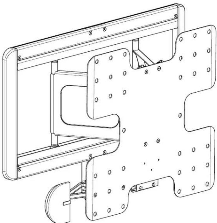
natural_image
Technical line drawing of a mechanical assembly with mounting brackets and mounting holes (no text or symbols)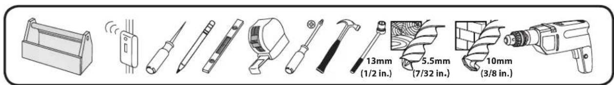
Sanus Systems
2221 Hwy 36 West
Saint Paul, MN 55113 USA
Customer Service
Americas: 800-359-5520 • 651-484-7988 • info@sanus.com
Europe, Middle East, and Africa: +31 40 2324700 • europe.sanus@milestone.com
Asia Pacifi c: 86 755 8996 9226 · sanus.ap@milestone.com
sanus.com
©2010 Milestone AV Technologies, a Duchossois Group Company.
All rights reserved. Sanus is a division of Milestone.
All other brand names or marks are used for identification purposes and are trademarks of their respective owners.
 |  |  |  |  |
| EnglishWood stud walls | Concrete/Concrete Block Walls | Choose an Option Do Not Alternate View | ||
| FrançaisStructure de murs en bois | Murs en béton coulé ou en blocs de béton | Sélectionnez une option Interdit Autre vue | ||
| DeutschHolzbalkenwände | Beton-/Betonsteinwände | Wählen Sie eine Option | Tun Sie Folgendes nicht | Alternative Ansicht |
| EspañolParedes con montantes de madera | Paredes de hormigón o de bloques de hormigón | Elija una opción Prohibido Vista ampliada | ||
| PortuguêsParedes de pino de madeira | Paredes de concreto/Paredes de bloco de concreto | Escolha uma opção Não Exibição alternada | ||
| NederlandsMuren met houten balkenconstructie | Muren van beton/betonblokken | Kies een optie Niet Alternatieve weergave | ||
| ItalianoPareti con montanti in legno | Pareti in calcestruzzo/blocchi di calcestruzzo | Scegliere un'opzione Divieto | Visualizzazione alternativa | |
| ΕλληνικάΤοιχοι με ξύλινους ορθοστάτες | Τοιχοι από σκυρόδεμα/ τσιμεντόλιθους | Επιλέξτε μια επιλογή | Μην Εναλλακτική προβολή | |
| NorskVegger med trestendere | Betongvegger/vegger av betongblokker | Velg et alternativ | Forbudt Alternativ visning | |
| DanskVægge med trædyveler | Beton / betonblokvægge | Vælg en mulighed | Advarsel | Skift visning |
| SvenskaVäggar med tråreglar | Betong/Betongvägg | Välj ett alternativ | Gör inte | Annan vinkel |
| РусскийСтена с деревянным каркасом | Стены из бетона/бетонных блоков | Выберите вариант | Запрещается | Альтернативный вид |
| polskiDrewniane ściany szkieletowe | Ściany z betonu lub pustaków betonowych | Wybrać opcję Nie należy: | Widok z innej strony | |
| ČeskyZdi s dřevěnými výztuhami | Zdi z betonu/panelů | Vyberte jednu možnost | Nedělat | Alternativní zobrazení |
| TürkçeAhşap Profilli Duvarlar | Beton/Beton Blok Duvarlar | Seçeneklerden Birini Belirleyin | Yapılmaması Gerekenler | Diğer Görünüm |
| 日本語木製スタッド壁 | コンクリート/コンクリートブロック壁 | オプションの選択 | 禁止事項 | 別の角度からの図 |
| 中文木墙柱端壁 | 混凝土/混凝土砌块墙 | 选择一个选项 | 请勿 | 交換视图 |
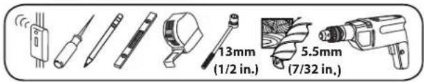
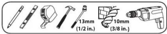
| EnglishTools required | WARNING: This product contains small items that could be a choking hazard. | CAUTION / WARNING | Repeat Step Heavy! Assistance | Required. |
| FrançaisOutils nécessaires | Ce produit contient de petites pièces qui peuvent représenter un risque d'étouff ement. | ATTENTION/ AVERTISSEMENT! | Répétez l'étape | TRÈS LOURD ! Cette étape requiert deux personnes. |
| DeutschBenötigte Werkzeuge | Dieses Produkt enthält kleine Teile, die zum Erstickungstod führen können. | VORSICHT / WARNUNG | Wiederholen Sie den Schritt | VORSICHT, SCHWER! Bei diesem Schritt werden Sie Hilfe benötigen. |
| EspañolHerramientas necesarias | Este producto contiene piezas pequeñas que, si fuesen tragadas, podrían producir así xia. | PRECAUCIÓN /IADVERTENCIA! | Repita este paso | ¡PESADO! Necesitará ayuda para realizar esta operación. |
| PortuguêsFerramentas necessárias | Este produto contém itens pequenos que podem oferecer risco de sufocamento. | ATENÇÃO / AVISO! | Repita a etapa | PESADO! Necessitará de ajuda nesta etapa. |
| NederlandsBenodigd gereedschap | Dit product bevat kleine onderdelen die stikkingsgevaar kunnen opleveren. | VOORZICHTIG/ WAARSCHUWING | Herhaal stap | ZWAAR! Voor het uitvoeren van deze stap is assistentie vereist. |
| ItalianoStrumenti richiesti | Questo prodotto comprende elementi di piccole dimensioni che potrebbero causare il soff ocamento. | PRECAUZIONE/ AVVERTENZA | Ripetere l'operazione | PESANTE! Per questa operazione, si avrà bisogno di aiuto. |
| ΕλληνικάΑλατούμενα εργαλεία | Το προϊόν autó περιλαμβάνει μικρά αντικείμενα που μπορεί να αποτελέσουν κίνδυνο πιγμού. | ΠΡΟΣΟΧΗ/ ΠΡΟΕΙΔΟΠΟΙΗΣΗ | Επαναλάβετε το βήμα | ΒΑΡΥ! Θα χρειαστείτε βοήθεια σ' autó το βήμα. |
| NorskNødvendig verktøy | Dette produktet inneholder små elementer som kan utgjøre kvelefare. | FORSIKTIG/ADVARSEL | Genta trinn | TUNGT! Du vil trenge hjelp til denne operasjonen. |
| DanskRedskaber, der skal bruges | Dette produkt indeholder små dele, som kan forårsage kvælning, hvis de bliver slugt. | FORSIGTIG/ADVARSEL | Gentag trin | TUNGT! Du skal bruge hjælp, når du udfører dette trin. |
| SvenskaVerktyg som behövs | Den här produkten innehåller små delar som kan utgóra kvävningsrisk. | FÖRSIKTIGHET/WARNING | Upprepa steg | TUNGT! Du kommer att behöva hjälp under det här steget. |
| РусскийНеобходимые инструменты | В изделии есть мелкие детали, которые могут стать причиной удушения при попадании в дыхательные пути. | ПРЕДУПРЕЖДЕНИЕ/ ПРЕДУПРЕЖДЕНИЕ | Повторить действие | БОЛЬШОЙ ВЕС! При выполнении данной операции вам понадобится помощь. |
| polskiWymagane narzędzia | Produkt zawiera małe elementy, które mogą grozić zakrztuszeniem. | UWAGA / OSTRZEŻENIE | Powtórzyć krok | СІЁŻКІЕ! W tej czynności potrzebna będzie pomoc drugiej osoby. |
| CeskyPožadované nástroje | Tento výrobek obsahuje malé součástky, které hrozí rizikem zadušení. | POZOR / VAROVÁNÍ Opakovat krok | ТЕЁŻКÉ! K tomuto kroku budete potřebovat pomocnika. | |
| TürkçeGereken Aletler | Bu ürün, boğulma tehlikesine neden olabilecek küçük parçalar içermektedir. | DİKKAT / UYARI Adım | Tekrarlayın | AĞIR MALZEME! Bu aşamada yardıma ihtiyacınız vardır. |
| 日本語必要なツール | 本製品には小さい部品が付属しており、窒息の危険性があります。 | 注意 / 警告 手順の繰り返し | 重量あり!この操作は2人で行ってください。 | |
| 中文需要的工具 | 此产品包含可能带来窒息危险的小组件。 | 小心 / 警告 重复步骤 | 支架臂很重!该步骤需要协助。 | |
 |  |
| EnglishTroubleshooting and Maintenance | This End Up |
| FrançaisDépannage et maintenance Ce côté vers le haut | |
| DeutschFehlerbehebung und Wartung Dieses Ende nach oben | |
| EspañolResolución de problemas y mantenimiento | Este extremo hacia arriba |
| PortuguêsSolução de problemas e manutenção | Esta extremidade para cima |
| NederlandsProbleemoplossing en onderhoud | Deze zijde boven |
| ItalianoRisoluzione dei problemi e manutenzione | Alto |
| ΕλληνικάΑντιμετώλιση προβλημάτων και Συντήρηση | Με autó to ákρο προς τα επάνω |
| NorskFeilsøking og vedlikehold Denne siden opp | |
| DanskFejlfi nding og Vedligeholdelse Denne ende skal være opad | |
| SvenskaFelsökning och underhåll Denna sida upp | |
| РусскийУстранение неисправностей и обслуживание | Этим концом вверх |
| polskiRozwiązywanie problemów i konserwacja | Tym końcem do góry |
| ČeskyŘešení problémů a údržba Tímto koncem vzhůru | |
| TürkçeSorun Giderme ve Bakım Bu U; Yukarı | |
| 日本語トラブルシューティングとメンテナンス | この面を上にします |
| 中文故障排除与维护 此端向上 |
English
IMPORTANT SAFETY INSTRUCTIONS – SAVE THESE INSTRUCTIONS – PLEASE READ ENTIRE MANUAL BEFORE USING THIS PRODUCT
For best results, reference both the text and illustrations when using this manual. Cut along the dashed lines to match your language with the illustrations.
English Text Pages 6
Français
INFORMATIONS IMPORTANTES CONCERNANT LA SÉCURITÉ – CONSERVEZ CES INSTRUCTIONS – VEUILLEZ LIRE ATTENTIVEMENT LE MANUEL AVANT D'UTILISER CE PRODUIT
IMPORTANT SAFETY INSTRUCTIONS – SAVE THESE INSTRUCTIONS – PLEASE READ ENTIRE MANUAL BEFORE USING THIS PRODUCT
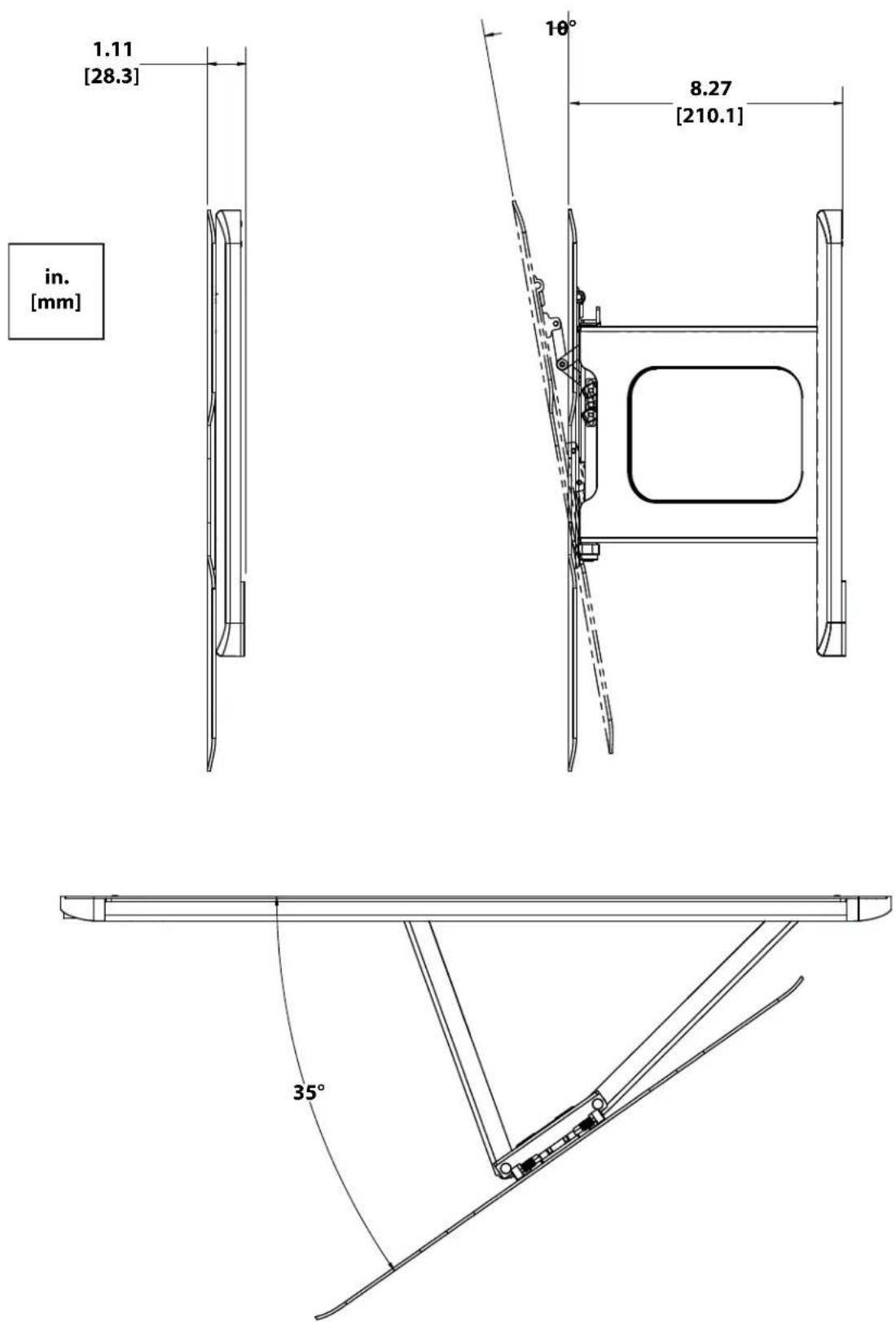
Specifications
Weight capacity: 27.22 kg (60 lbs) includes TV and any accessories
Swivel: ±35°
Tilt: -10^
▲ CAUTION: Avoid potential personal injuries and property damage!
Do not use this product for any purpose not explicitly specified by manufacturer.
The wall must be capable of supporting five times the weight of the monitor and mount combined.
This product is not designed for use in metal stud walls!
If you do not understand these instructions, or have doubts about the safety of the installation, assembly or use of this product, contact manufacturer Customer Service or call a qualified contractor.
■ Manufacturer is not responsible for damage or injury caused by incorrect assembly or use.
![in. [mm] 15.75 [400.0] 11.81 [300.0] 7.87 [200.0] 15.75 [400.0] 11.81 [300.0] 7.87 [200.0] 12.30 [312.4] 13.50 [342.9] 17.00 [431.8] 5.01 [127.4] 25.20 [640.1]](/content/2026/04/673653/images/c6de1b1b56357fea6ef99a19471779f353e31e1040f67921e42d74a8b4ea3d72.jpg)
CAUTION:

Supplied Parts and Hardware.
Before starting assembly, verify all parts are included and undamaged. If any parts are missing or damaged, do not return the damaged item to your dealer; contact Customer Service. Never use damaged parts!
NOTE: Not all hardware included will be used.
![Wound Seed SANUS WARM-308, Wall Rate Template Solid Concrete or Concrete Block [01] x 1](/content/2026/04/673653/images/5bd377cd47466d70f5b71fd1666ba59a705f6137459d568ffec84fb1f63495b3.jpg)
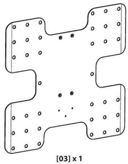
natural_image
Symmetrical abstract diagram with four rounded rectangular regions and scattered dots, labeled [03] x 1 at bottom (no text or symbols within shapes)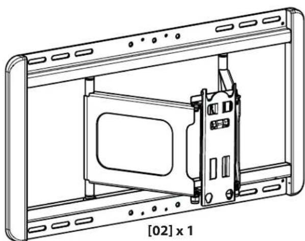
natural_image
Technical line drawing of a device housing with a component labeled [02] x 1 (no text or symbols on the diagram itself)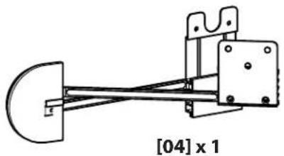
natural_image
Mechanical assembly diagram showing a linkage mechanism with no visible text or symbols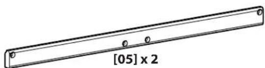
natural_image
Technical line drawing of a rectangular beam with evenly spaced holes and dimension label [05] x 2 (no text or symbols beyond the label)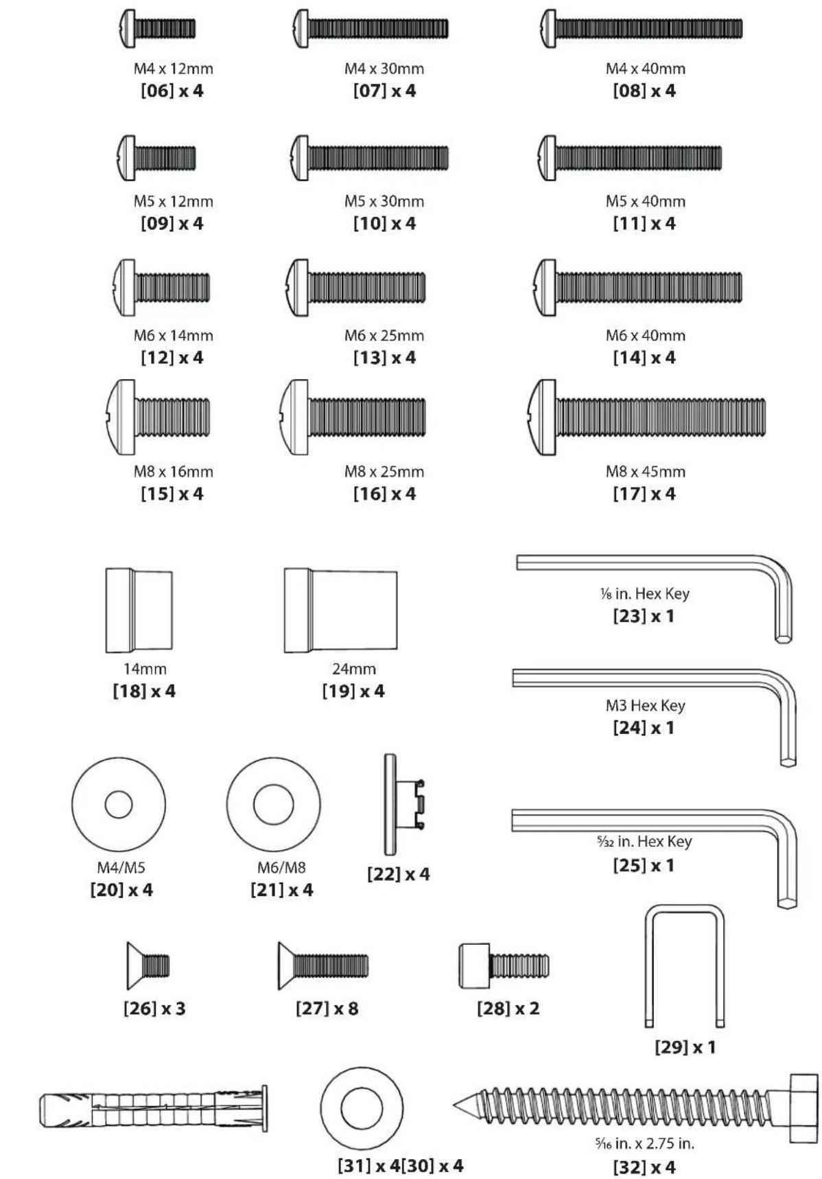
CAUTION:
Install TV Brackets
Before you begin, hand thread screws into the threaded inserts on the back of your TV to determine the correct screw diameter (M4, M5, M6, or M8). Verify that there are adequate threads to secure the brackets to the monitor. If you encounter resistance, stop immediately and contact customer service.
▲ CAUTION: Avoid potential personal injuries and property damage! Use the shortest screw and spacer combination to accommodate your needs. Using hardware that is too long may damage your monitor's internal components.
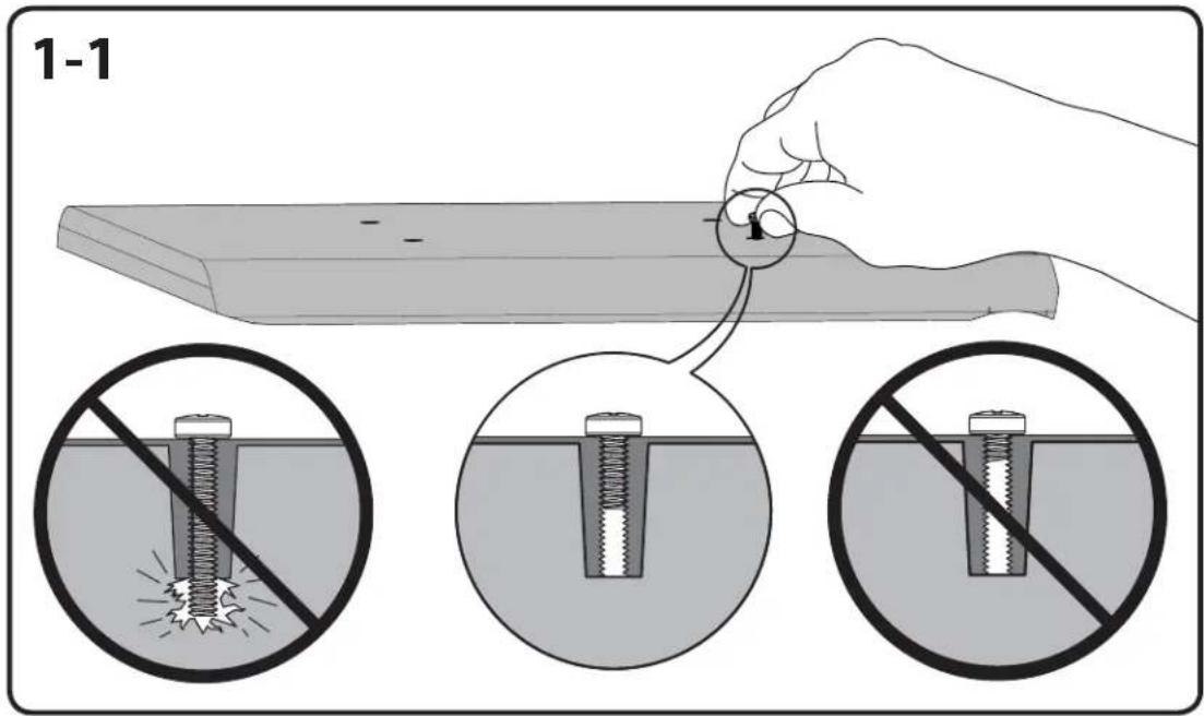
For TVs with a flat back. Ensure that the bracket is level on the back of the TV. Standard confi gurations are shown. If you need extra space to accommodate cables, recesses, or protrusions, see an installation option (1-2 or 1-3) that uses spacers. For special applications, or if you are uncertain about your hardware selection, contact Customer Service.
![[03]](/content/2026/04/673653/images/f214077b1c2e08b8c2c682b2f0c861a0cbb049fbc8da4b0be4412112effe0a04.jpg)
![M4 [06] [20] [03]](/content/2026/04/673653/images/98bd34d12a7b53d78fb57f799c3cbec17cf1108a4dbed2f8ddb403dad2112f4c.jpg)
![M5 [09] [20] [03]](/content/2026/04/673653/images/5cc9c7988f81894d32a2d402c4dc0bc292cae8b741a17608a6c506d35c909ae7.jpg)
![M6 [12] [21] [03]](/content/2026/04/673653/images/aef1fb943a5573ee7999dfbbc6df0cb04b9a702d6771b9324e410969573190d8.jpg)
![M8 [15] [21] [03]](/content/2026/04/673653/images/f7c8d0676765186a71e1e1bdee972544a45c570fa49d3c79ee8906bd0432d941.jpg)
1-2
![A [18] [22]](/content/2026/04/673653/images/af20fd3d37562e46e87cb958ea4f56eeb847ebcb2a3949573d63deba069508b9.jpg)

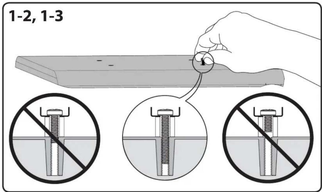
For TVs with an irregular/obstructed back. Ensure that the bracket is level on the back of the TV. Standard configurations are shown. For special applications, or if you are uncertain about your hardware selection, contact Customer Service.
![[03]](/content/2026/04/673653/images/658ce9ffbf6e02576007372b44d479ff743df51cade4b7a2f73c248a991b799f.jpg)
![M4 [07] [20] [03] [22] [18]](/content/2026/04/673653/images/927287ccae45bb7ee2aed7cfc60017d7932b406ad6dba58d1250ca00fdb71da4.jpg)
![M5 [10] [20] [03] [22] [18]](/content/2026/04/673653/images/b86a661dbe3cb8bda41c031d1bfa440d4d2dd8827bc2c95de2fa868e228df8b2.jpg)
![M6 [13] [21] [03] [22] [18]](/content/2026/04/673653/images/2474f20e1009cd2fb97a0d1cedc1e36e7d21c2200e7c42cc088e3ded2a1fbf46.jpg)
![M8 [16] [21] [03] [22] [18]](/content/2026/04/673653/images/766951ef6fa87363c8eee03bc14d9c9cd9db06b57719ce2dc37028cc9ab53e97.jpg)

For TVs with an irregular/obstructed back. Ensure that the bracket is level on the back of the TV. Standard configurations are shown. For special applications, or if you are uncertain about your hardware selection, contact Customer Service.

1-3
![A [19] [22]](/content/2026/04/673653/images/3581d28fb3488e0ec47e8ce762653518a0f14c163961c847a0087d2eb376439b.jpg)
![[03] [19]](/content/2026/04/673653/images/cf713a338945dc29b9cd95c0f5eafe600a7d6ead392436d4b5269052566f8147.jpg)
![M4 [08] [20] [03] [22] [19]](/content/2026/04/673653/images/8c3109feae319e110253c9a7f03d1947d186df01a66cebcf3a3edf7921258b3c.jpg)
![M5 [11] [20] [03] [22] [19]](/content/2026/04/673653/images/2050ccba05de78a95bbe866c64513918e9d3e04a28c525e421d954334e87679b.jpg)
![M6 [14] [21] [03] [22] [19]](/content/2026/04/673653/images/807d122bcf231d7e6be410ad4690e79f28f8dc66b2df6e1b099b7458f6c663e8.jpg)
![M8 [17] [21] [03] [22] [19]](/content/2026/04/673653/images/99289e5d1f1986e5ab636901b145cfb09b6fce52e467e903e3c3f91babc97cb6.jpg)
To prepare the wall plate for mounting:
Slide the arms of the wall plate [02] together and insert the slide lock [29] into place. This will lock the arms into full extension making the wall plate mounting and TV attachment easier.
Install the locking screws [28] into the sides of the face plate using the 316 in hex key [25]. Screw in only until the end of the screw is flush with the inside of the plate. This will allow the TV to be mounted without interference.
![[29] [02] [29] [25] [28] [28]](/content/2026/04/673653/images/a22302b897d88cbdb1ef78df7498a1589cc17c742c6afae41d40d7b8c48d0de2.jpg)

SANUS™
VISIONMOUNT
CAUTION:
Wall Mounting
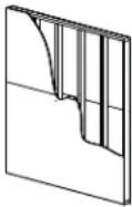
3-1: Wood Stud Mounting
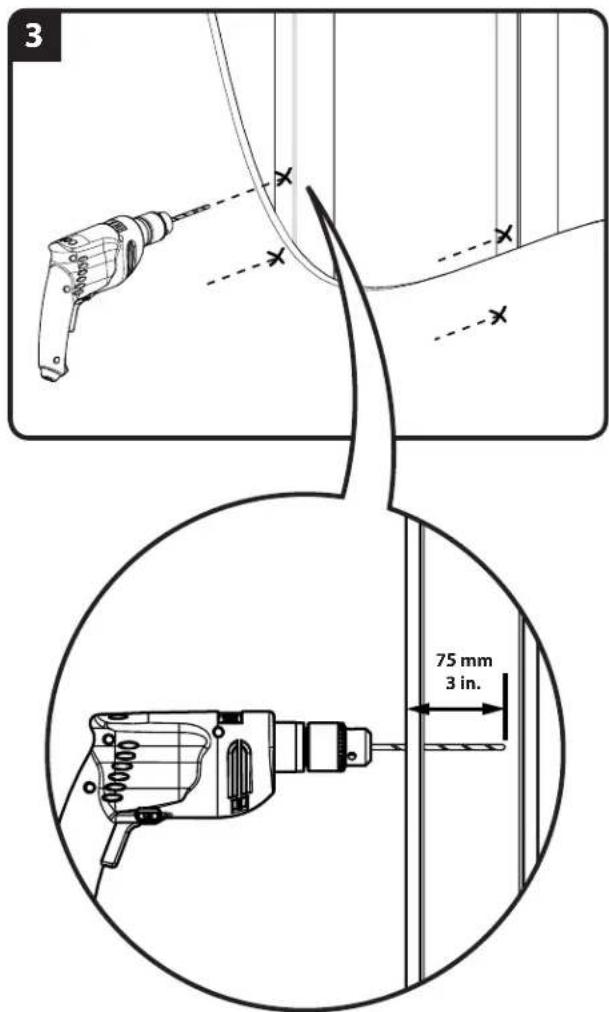
▲ CAUTION: Improper use could reduce the holding power of the lag bolt. To avoid potential injuries or property damage:
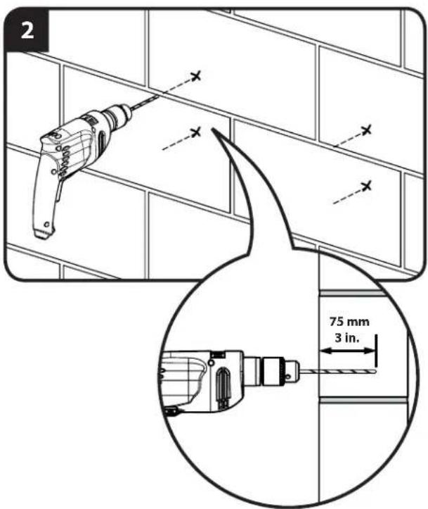
Pilot holes MUST be drilled to a depth of 75 mm (3 in.), using a 5.5 mm (7/32 in.) diameter drill bit.
DO NOT over-tighten the lag bolts [32].
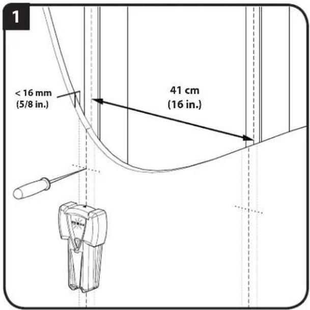
■ Any material covering the wall must not exceed 16 mm (5/8 in.).
Minimum wood stud size: common 2 x 4 in. (nominal 1.5 x 3.5 in.)
3-2: Solid Concrete and Concrete Block Mounting
▲ CAUTION: Improper use could reduce the holding power of the lag bolt. To avoid potential injuries or property damage:
Pilot holes MUST be drilled to a depth of 75 mm (3 in.), using a 10 mm (3/8 in.) diameter drill bit.
Be sure the anchors [30] seat flush with the concrete surface.
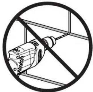
* Mount wall plate directly onto the concrete surface.
* Never drill into the mortar between blocks.
✗ DO NOT over-tighten the lag bolts [32].
Minimum solid concrete thickness: 8 in.
Minimum concrete block size: 8 x 8 x 16 in.
Wood Stud Wall Mounting – See Cautions in Step 3.
- Locate studs. Verify the center of the stud with an awl or thin nail or use an edge to edge stud fi nder.
- Using the wall plate template [01], level the template [01] and mark the hole locations.
- Drill pilot holes as illustrated.
- Place the wall plate against the wall. Tighten the lag bolts [32] only until the washers [31] are pulled firmly against the wall plate [02].
![2 SANUS [01]](/content/2026/04/673653/images/910ffd42d988e279e649912b6ed7304ab82da650efba48bbdf816baae9215d97.jpg)
![4 [02] [31] [32]](/content/2026/04/673653/images/c3c3c38c7157c78a547f50fd8279c35f29424b45477dea4a09bcbc9763c67668.jpg)
6900-002066<02>
3-2
![1 [01]](/content/2026/04/673653/images/b82adb847ecbe40d046d944ece8dee3c13ab4f98aa0693513f8bf352be8e4039.jpg)
natural_image
Diagram of a drill bit crossed out by a diagonal line, enclosed in a circle (no text or symbols)![3 [30]](/content/2026/04/673653/images/571350bc1332700602cbdace3dafa186e1f7e67cf2fe069717a515e893dc175e.jpg)
Solid Concrete and Concrete Block Mounting – See Cautions in Step 3.
- Using the wall plate template[01], level the template [01] and mark the hole locations.
- Drill pilot holes as illustrated.
- Insert lag bolt anchors [30].
- Place the wall plate against the wall. Tighten the lag bolts [32] only until the washers [31] are pulled firmly against the wall plate [02].
![4 [02] [31] [32]](/content/2026/04/673653/images/1bcc85aea31ea429db3ebc5b55c9b23dd0acccda9be7e8653f44a00568df516c.jpg)
Install wall plate covers and the wire management assembly (optional) onto the wall plate.
- Mount the upper cover [05] using the 18 in. hex key [23] to install four screws [27].
- Mount the lower cover [05] using the 18 in. hex key [23] to install four screws [27] while (optional) fitting the rear mount of the wire management assembly [04] between the cover [05] and the lower horizontal of the wall plate [02].
Note: Do not install the rear mount of the wire management assembly [04] unless you intend to install the front mount of the wire management assembly [04] in Step 6.
![[05] [27] [02] [23] 4 [05] [27] 4 [04] [05] [23] [27] [04] [05]](/content/2026/04/673653/images/cea4ee8faaa0815067e55228e686184016ca7c5d89882521c659a12795c55c9e.jpg)
Attach TV to Wall Plate
HEAVY! You will need assistance with this step.
-
Hang the TV with mounting bracket [03] onto the face plate of the wall plate [02]. The lower mounting knobs of the mounting bracket [03] will fit into the keyhole slots of the face plate of the wall plate [02] while the upper knobs will drop into the top slots of the face plate of the wall plate [02].
-
Secure the TV to the face plate of the wall plate [02] by tightening the locking screws [28] with the 316 in. hex key [25] until they capture the upper knobs of the bracket [03].
![[03] [02] [03] [02]](/content/2026/04/673653/images/e6243eec4f37b668e4c5b73b533d03727a8b2ee693612f786d7653407b9cce4d.jpg)
![[03] [25] [28] [28] [02]](/content/2026/04/673653/images/9e9bcdb678111d56382515e18d55f91432152054eae1ff1f9414292eb1d7d3bc.jpg)
Install the wire management assembly to the TV bracket (optional).
Fit the front mount of the wire management assembly [04] onto the back of the TV bracket [03] using the 18 in. hex key [23] to install three screws [26].
Note: Do not install the front mount of the wire management assembly [04] unless you have installed the rear mount of the wire management assembly [04] in Step 4.
![Note: Do not install the front mount of the wire management assembly [04] unless you have installed the rear mount of the wire management assembly [04] in Step 4. [03] [04] [26] [23] [04]](/content/2026/04/673653/images/268a0b957eea7ab4e93fcaa7235df805a31fdacce3b6afe27ee7931656c8dae8.jpg)
![1 [04]](/content/2026/04/673653/images/c5bbb74a55a328bf621af657e1936d2ad6d837cd258965c3cee321fe1e607f63.jpg)
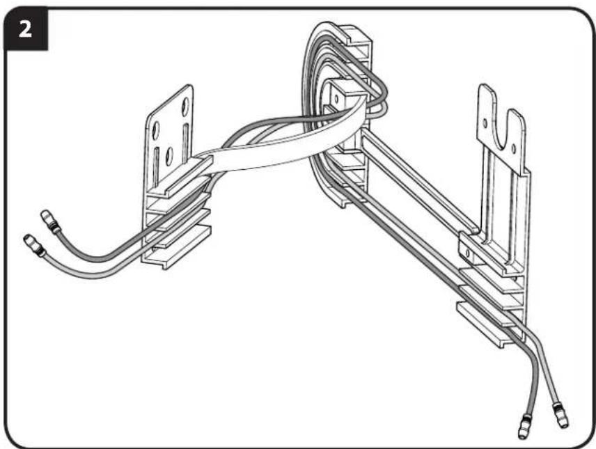
Wire Management (Optional - see Steps 4 and 6)
Plug the required wires and/or cables into the TV. Slide the three covers of the wire management assembly [04] off the front (TV bracket mount), rear (wall plate mount), and center (floating). Route the wires and/or cables through the three sections, then replace the covers.
natural_image
Technical line drawing of a mechanical assembly with coiled wires and mounting brackets (no text or symbols)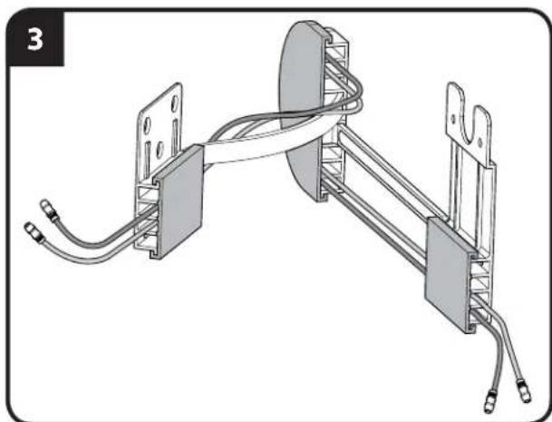
natural_image
Technical diagram of a mechanical assembly with two vertical plates, coiled cables, and connectors (no text or symbols)Adjustments
Adjust up / down tilt tension by hand or using the M3 hex key [24].
![[24]](/content/2026/04/673653/images/6c4cdcfbfd05a950fd65ebb7b62dfc6551431020ab2ab54b9dfa22df9476a281.jpg)
Storage
After setup is complete, remove slide lock [29] from the locking position A and fit it into the grooves of one of the slides for storage B.
![A [02] [29]](/content/2026/04/673653/images/3e6ddf282acd748b523c70d9ac8ed8655c14e367cc2adb95faedd53cca957c8b.jpg)
6900-002066<02>
![B [29] [02]](/content/2026/04/673653/images/bd2b89cf08f83ad85c03d33811156c8eacf2520dd7461eff9d4008d2e6a5b5e6.jpg)
ATTENTION:
INFORMATIONS IMPORTANTES CONCERNANT LA SÉCURITÉ – CONSERVEZ CES INSTRUCTIONS – VEUILLEZ LIRE ATTENTIVEMENT LE MANUEL AVANT D'UTILISER CE PRODUIT
Spécifi cations
Milestone AV Technologies and its affiliated corporations and subsidiaries (collectively, "Milestone"), intend to make this manual accurate and complete. However, Milestone makes no claim that the information contained herein covers all details, conditions, or variations. Nor does it provide for every possible contingency in connection with the installation or use of this product. The information contained in this document is subject to change without notice or obligation of any kind. Milestone makes no representation of warranty, expressed or implied, regarding the information contained herein. Milestone assumes no responsibility for accuracy, completeness or sufficiency of the information contained in this document.