
B 35 - Heating Master - Free user manual and instructions
Find the device manual for free B 35 Master in PDF.

User questions about B 35 Master
0 question about this device. Answer the ones you know or ask your own.
Ask a new question about this device
Download the instructions for your Heating in PDF format for free! Find your manual B 35 - Master and take your electronic device back in hand. On this page are published all the documents necessary for the use of your device. B 35 by Master.
USER MANUAL B 35 Master
natural_image
Icon of an open book with an exclamation mark, enclosed in a diamond shape with a yellow diagonal stripe (no text or symbols)USER AND MAINTENANCE MANUAL
IMPORTANT: In order to have a correct function you must use an electrical generator in class G3 or more (frequency variation ±1%, tension variation ±2%). The maximum power of electrical generator must be three time the nominal power of device that you must connected.
TECHNICAL DATA TABLE - TABELLA DATI TECNICI - TECHNISCHE DATEN - TABLA DE DATOS TÉCNICOS - TABLEAU DES DONNEES TECHNIQUES - TABEL TECHNISCHE GEGEVENS - TABELA DE DADOS TÉCNICOS - TABEL OVER TEKNISKE DATA - TEKNISET TIEDOT SISÄLTÄVÄ TAULUKKO - TABELL MED TEKNISKE DATA - TABELL ÖVER TEKNISKA DATA - TABELA DANYCH TECHNICZNYCH - ТАБЛИЦА ТЕХНИЧЕСКИХ ДАННЫХ - TABULKA TECHNICKÝCH ÚDAJŮ - MŰSZAKI ADATTÁBLÁZAT - PREGLEDNICA ТЕННИČNIH PODATKOV - TEKNÝK VERÝLER TABLOSU - TABLICA SA ТЕННИČKIM PODACIMA - TECHNINIR DUOMENŘ LENTELĚ - TEHNISKO DATU TABULA - TEHNILISTE ANDMETE TABEL - TABEL DATE TEHNICE - TABULKA TECHNICKÝCH ÚDAJOV - ТАБЛИЦА ТЕХНИЧЕСКИ ДАННИ - ТАБЛИЦЯ ТЕХНИЧНИХ ДАНИХ - TABELA S TEHNIČKIM PODACIMA - ΠΙΝΑΚΑΣ ТЕХNIKΩΝ ΣΤΟΙΧΕΙΩΝ - 技术参数 - ТЕХНИКАЛЫҚ КӨРСЕТКІШТЕР КЕСТЕСІ
| B 35CED B 70CED | |||
 MAX MAX | 10 kW-кВт8.600 kcal/h-ккал/ч34.200 Btu/h-БTE/ч | 20 kW-кВт17.200 kcal/h-ккал/ч68.300 Btu/h-БTE/ч | |
 | 280 m3/h-м3/ч 400 m3/h-м3/ч | ||
 | 0,8 kg/h-кг/ч 1,6 kg/h-кг/ч | ||
 | DIESEL-KEROSENEDизель-керосин | DIESEL-KEROSENEDизель-керосин | |
 | 19 l-л 19 l-л | ||
 | ~220-240 V-B(-15%÷10%)50/60 Hz-Гц0,35 A0,08 kW-кВт | ~220-240 V-B(-15%÷10%)50/60 Hz-Гц0,8 A0,18 kW-кВт | |
| RPM | 1425 2850 | ||
 | 0,20 bar-6ap 0,36 bar-6ap | ||

IMPORTANT: In order to have a correct function you must use an electrical generator in class G3 or more (frequency variation ±1%, tension variation ±2%). The maximum power of electrical generator must be three time the nominal power of device that you must connected.
TECHNICAL DATA TABLE - TABELLA DATI TECNICI - TECHNISCHE DATEN - TABLA DE DATOS TÉCNICOS - TABLEAU DES DONNEES TECHNIQUES - TABEL TECHNISCHE GEGEVENS - TABELA DE DADOS TÉCNICOS - TABEL OVER TEKNISKE DATA - TEKNISET TIEDOT SISÄLTÄVÄ TAULUKKO - TABELL MED TEKNISKE DATA - TABELL ÖVER TEKNISKA DATA - TABELA DANYCH TECHNICZNYCH - ТАБЛИЦА ТЕХНИЧЕСКИХ ДАННЫХ - TABULKA TECHNICKÝCH ÚDAJŮ - MŰSZAKI ADATTÁBLÁZAT - PREGLEDNICA ТЕННИČNIH PODATKOV - TEKNÝK VERÝLER TABLOSU - TABLICA SA ТЕННИČKIM PODACIMA - TECHNINIŘ DUOMENŘ LENTELĚ - TEHNISKO DATU TABULA - TEHNILISTE ANDMETE TABEL - TABEL DATE TEHNICE - TABULKA TECHNICKÝCH ÚDAJOV - ТАБЛИЦА ТЕХНИЧЕСКИ ДАННИ - ТАБЛИЦЯ ТЕХНИЧНИХ ДАНИХ - TABELA S ТЕННИČKIM PODACIMA - ПІНАКАЗ ТЕХNIKΩΝ ΣΤΟΙΧΕΙΩΝ - 技术参数 - ТЕХНИКАЛЫҚ КӨРСЕТКІШТЕР КЕСТЕСІ
| B 100CED B 150CED B 300CED | |||
 MAX MAX | 29 kW-кВт25.000 kcal/h-ккал/ч99.300 Btu/h-БТЕ/ч | 44 kW-кВт37.900 kcal/h-ккал/ч150.500 Btu/h-БТЕ/ч | 88 kW-кВт75.800 kcal/h-ккал/ч301.000 Btu/h-БТЕ/ч |
 | 800 m^3/h - m^3/ч 900 m^3/h | -m^3/ч 1.800 m^3/h - m^3/ч | |
 | 2,3 kg/h-кг/ч 3,5 kg/h-кг/ч 7 kg/h-кг/ч | ||
 | DIESEL-KEROSENEDизель-керосин | DIESEL-KEROSENEDизель-керосин | DIESEL-KEROSENEDизель-керосин |
 | 44 I-л 44 I-л 105 I-л | ||
 | ~220-240 V-B(-15%÷10%)50 Hz-Гц1 A0,23 kW-кВт | ~220-240 V-B(-15%÷10%)50/60 Hz-Гц1,2 A0,28 kW-кВт | ~220-240 V-B(-15%÷10%)50/60 Hz-Гц2,4 A0,56 kW-кВт |
| ~220-240 V-B(-15%÷10%)60 Hz-Гц1 A0,23 kW-кВт | |||
| RPM | 2850 2850 2850 | ||
 | 0,27 bar-бар 0,34 bar-бар 0,40 bar-бар | ||

IMPORTANT: In order to have a correct function you must use an electrical generator in class G3 or more (frequency variation ±1%, tension variation ±2%). The maximum power of electrical generator must be three time the nominal power of device that you must connected.
TECHNICAL DATA TABLE - TABELLA DATI TECNICI - TECHNISCHE DATEN - TABLA DE DATOS TÉCNICOS - TABLEAU DES DONNEES TECHNIQUES - TABEL TECHNISCHE GEGEVENS - TABELA DE DADOS TÉCNICOS - TABEL OVER TEKNISKE DATA - TEKNISET TIEDOT SISÄLTÄVÄ TAULUKKO - TABELL MED TEKNISKE DATA - TABELL ÖVER TEKNISKA DATA - TABELA DANYCH TECHNICZNYCH - ТАБЛИЦА ТЕХНИЧЕСКИХ ДАННЫХ - TABULKA TECHNICKÝCH ÚDAJŮ - MŰSZAKI ADATTÁBLÁZAT - PREGLEDNICA ТЕННИČNIH PODATKOV - TEKNÝK VERÝLER TABLOSU - TABLICA SA ТЕННИČKIM PODACIMA - TECHNINÍŘ DUOMENŘ LENTELĚ - TEHNISKO DATU TABULA - TEHNILISTE ANDMETE TABEL - TABEL DATE TEHNICE - TABULKA TECHNICKÝCH ÚDAJOV - ТАБЛИЦА ТЕХНИЧЕСКИ ДАННИ - ТАБЛИЦЯ ТЕХНІЧНИХ ДАНИХ - TABELA S ТЕННИČKIM PODACIMA - ПІНАКАЗ ТЕХНИКΩΝ ΣΤΟΙΧΕΙΩΝ - 技术参数 - ТЕХНИКАЛЫҚ КӨРСЕТКІШТЕР КЕСТЕСІ
| B 35CEG B 70CEG B 100CEG B 150CEG | |||||
 MAX MAX | 10 kW-кВт8.600 kcal/h-ккал/ч34.200 Btu/h-БТЕ/ч | 20 kW-кВт17.200 kcal/h-ккал/ч68.300 Btu/h-БТЕ/ч | 29 kW-кВт25.000 kcal/h-ккал/ч99.300 Btu/h-БТЕ/ч | 44 kW-кВт37.900 kcal/h-ккал/ч150.500 Btu/h-БТЕ/ч | |
 | 280 m3/h-м3/ч 400 | m3/h-м3/ч 800 m3/h-м3/ч | 900 m3/h-м3/ч | ||
 | 0,8 kg/h-кг/ч 1,6 kg/h-кг/ч 2,3 kg/h-кг/ч 3,5 kg/h-кг/ч | ||||
 | DIESEL-KEROSENE дизель-керосин | DIESEL-KEROSENE дизель-керосин | DIESEL-KEROSENE дизель-керосин | DIESEL-KEROSENE дизель-керосин | |
 | 19 I-л 19 I-л 44 | I-л 44 I-л | |||
 | ~220-240 V-B(-15%÷10%)50 Hz-Гц0,35 A0,08 kW-кВт | ~220-240 V-B(-15%÷10%)50 Hz-Гц0,8 A0,18 kW-кВт | ~220-240 V-B(-15%÷10%)50 Hz-Гц1 A0,23 kW-кВт | ~220-240 V-B(-15%÷10%)50 Hz-Гц1,2 A0,28 kW-кВт | |
| RPM | 1425 2850 2850 | 2850 | |||
 | 0,20 bar-бар | 0,36 bar-бар | 0,27 bar-бар | 0,34 bar-бар | |

IMPORTANT: In order to have a correct function you must use an electrical generator in class G3 or more (frequency variation ± 1% , tension variation ± 2% ). The maximum power of electrical generator must be three time the nominal power of device that you must connect.
FIGURES - FIGURE - ABBILDUNGEN - FIGURAS - FIGURES - FIGUREN - FIGURAS - FIGURER - KUVAT - FIGURER - BILDER - RYSUNKI - РИСУНКИ - ОВ- RÁZKY - ÁBRÁK - SLIKE - ŞEKİLLER - SLIKE - PAVEIKSLÈLIAI - ATTËLI - JO- ONISED - FIGURI - OBRÁZKY - CXEMI - МАЛЮНКИ - SLIKE - EIKONEΣ - 图
- СУРЕТТЕР
natural_image
Technical line drawing of a mechanical device with wheels and a motor, no text or symbols present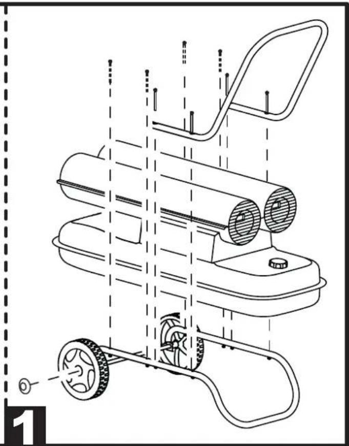
natural_image
Technical line drawing of a mechanical device with wheels and a handle, showing internal components and alignment lines (no text or symbols)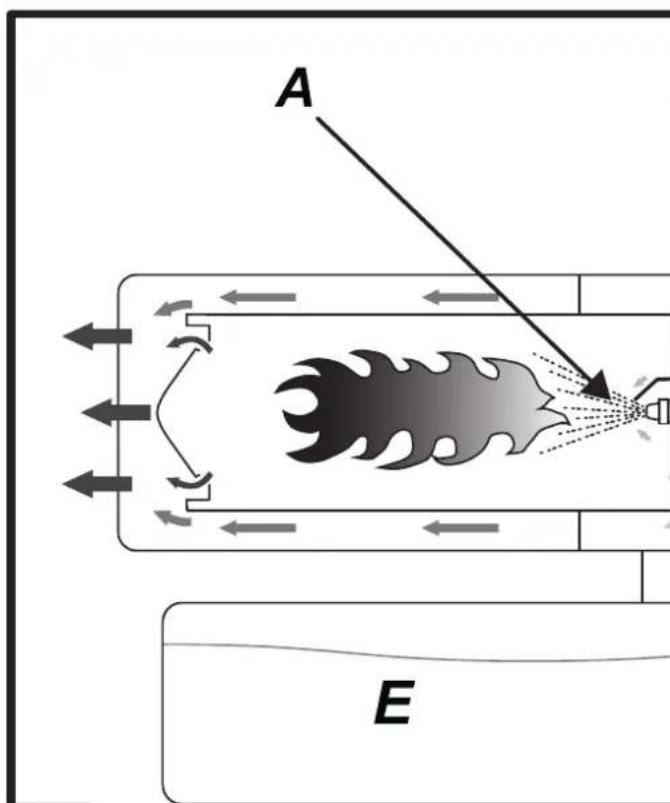
2
FIGURES - FIGURE - ABBILDUNGEN - FIGURAS - FIGURES - FIGUREN - FIGURAS - FIGURER - KUVAT - FIGURER - BILDER - RYSUNKI - РИСУНКИ - ОВ- RÁZKY - ÁBRÁK - SLIKE - ŞEKİLLER - SLIKE - PAVEIKSLÈLIAI - ATTËLI - JO- ONISED - FIGURI - OBRÁZKY - CXEMI - МАЛЮНКИ - SLIKE - EIKONEΣ - 图
- СУРЕТТЕР
natural_image
Line drawing of a hand pressing a button on an electrical outlet (no text or symbols)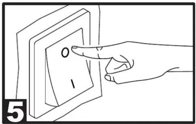
IMPORTANT: READ AND UNDERSTAND THIS OPERATIONAL MANUAL BEFORE PERFORMING ASSEMBLY, COMMISSIONING OR MAINTENANCE ON THIS HEATER. INCORRECT USE OF THE HEATER CAN CAUSES SERIOUS INJURY.
KEEP THIS MANUAL FOR FURTHER REFERENCE.
1. INFORMATION REGARDING
SAFETY
WARNINGS

IMPORTANT: This air heater has designed for mobile and temporary professional applications. It has not been designed for domestic use nor for thermal support of human.

IMPORTANT: This appliance is not ended for use by persons (including children) with reduced physical, sensory and mental capacities or with lack of experience or knowledge unless super-d by a person responsible for theirity. Children must be supervised to be sure they neither do nor play with appliance.

DANGER: Suffocation by carbon oxide can be fatal.
The first symptoms of suffocation by carbon monoxide are similar to those of flu with headache, light-headedness and/or nausea. These symptoms could be caused by the faulty functioning of the heater. IF THESE SYMPTOMS SHOULD OCCUR, DO OUTDOORS IMMEDIATELY and have the generator repaired by a technical after-sales centre.
▶▶1.1. TOPPING-UP:
▶1.1.1. Staff in charge of top-up must be qualified and understand the manufacturer's instructions and the Standards in force regarding safe top-up of the heaters.
▶1.1.2. Only use the type of fuel expressly specified on the heater identification plate.
▶1.1.3. Before topping-up, switch the heater off and wait for it to cool down.
▶1.1.4. The fuel storage tanks must be in a separate structure.
▶1.1.5. All fuel tanks must be at a minimum safety distance from the heater, according to the Standards in force.
▶▶1.2. SAFETY:
▶1.1.6. The fuel must be kept in rooms where the floor does not allow penetration and dripping of the same onto flames below, which can cause ignition.
▶1.1.7. The fuel must be stored in compliance with the Standard in force.
▶1.2.1. Never use the heater in rooms where petrol, solvents for paints or other highly inflammable vapours are present.
▶1.2.2. During use of the heater, follow all local regulations and the Standard in force.
▶1.2.3. The heaters in proximity of tarpaulin, curtains or other similar covering materials, must be situated at a safe distance from the same. It is advised to use fire-proof covering material.
▶1.2.4. Only use in well-ventilated areas. Set-up a suitable opening according to the Laws in force, with the purpose of introducing fresh air from outdoors.
▶1.2.5. Power the heater only with current that has voltage and frequency specified on the heater identification plate.
▶1.2.6. Only use extensions with three wires, appropriately connected to earth.
▶1.2.7. Minimum safety distances recommended, running between the heater and the inflammable substances are: front output = 2,5 m; side, at top and on rear = 1,5 m.
▶1.2.8. Put the heater in hot mode or running, on a stable level surface, in a way to prevent the risk of fire.
▶1.2.9. Keep animals at a safe distance from the heater.
▶1.2.10. Disconnect the heater from the mains socket when not in use.
▶1.2.11. When it is controlled by a thermostat, the heater can switch on at any time.
▶1.2.12. Never use the heater in frequently inhabited rooms, or in the bedroom.
▶1.2.13. Never block the air vent (rear side) or the air outlet (front side) of the heater.
▶1.2.14. When the heater is hot or connected to the mains electricity or functioning, it must never be moved, handled, topped-up or subject to any maintenance interventions.
▶1.2.15. Do not duct the air entering or exiting the heater.
▶1.2.16. Keep the hot parts of the heater at an adequate distance from inflammable or termolabile materials (including the power supply cable).
▶1.2.17. If the power supply cable is damaged, it must be replaced by the technical after-sales centre, in order to prevent all risks.
2. UNPACKING
▶2.1. Remove all packaging materials used to wrap and deliver the heater and dispose of them in compliance with the Standards in force.
▶2.2. Extract all articles from the packaging.
▶2.3. Control for any damage undergone during transport. If the heater appears damaged, inform the dealer, where the purchase was made, immediately.
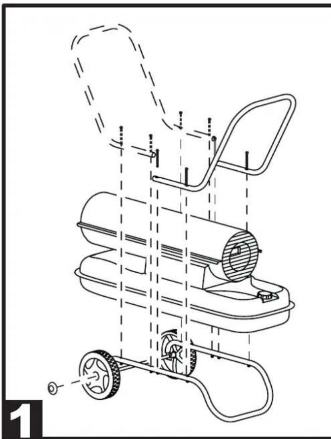
3. ASSEMBLY (29-44 kW)
(SEE FIG. 1)
These models have wheels and handle/s depending on the model. These components, complete with relative nuts and bolts, are situated in the heater box.
4. FUEL
WARNING: The heater only functions with DIESEL or KEROSENE.
Only use diesel or kerosene, to prevent the risk of fire or explosion. Never use petrol, naphtha, solvents for paints, alcohol or other highly inflammable fuels.
Use non-toxic anti-freeze additives in the case of very low temperatures.
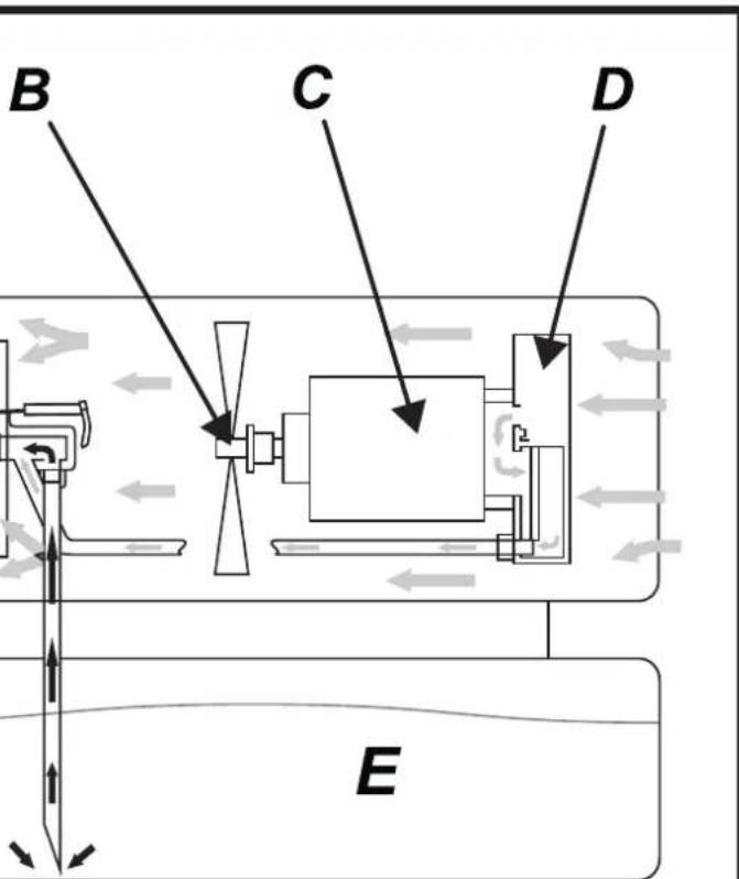
5. FUNCTIONING PRINCIPLES
The series of compressor products has a wide range of power. Models are available with both single and double combustion flanked chambers. For heaters with a double combustion chamber, the two combustion chambers can be used simultaneously for maximum power, or a single combustion chamber can be used for intermediate power.
(SEE FIG. 2)
A. Combustion chamber and heads,
B. Fan,
C. Motor,
D. Compressor,
E. Tank.
The compressor (D) started by the motor (C) compresses the air, which through the atomising nozzle, sucks up the fuel from the tank (E) due to the “VENTURI EFFECT”. On contact with the igniter, the atomised fuel ignites inside the combustion chamber (A). The combustion products are mixed with the flow of room air generated by the rotation of the fan (B) and pushed towards the outside of the heater. A photoresistance, connected to a circuit board, constantly checks the correct functioning of the heater, stopping the cycle in the event of anomalies.
6. FUNCTIONING
WARNING: Thoroughly read the "INFORMATION REGADRING SAFETY", before switching the heater on.
▶▶6.1. SWITCHING THE HEATER ON:
▶6.1.1. Follow all instructions relative to safety.
▶6.1.2. Check the presence of fuel in the tank.
▶6.1.3. Close the tank cap.
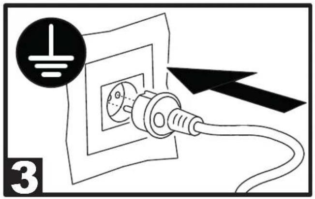
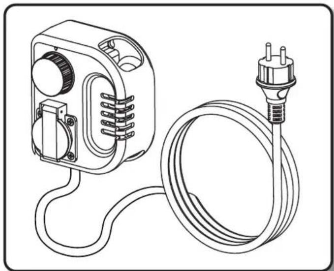
▶6.1.4. Connect the power supply plug to the mains electricity (SEE VOLTAGE IN "TECHNICAL DATA TABLE") (SEE FIG. 3).
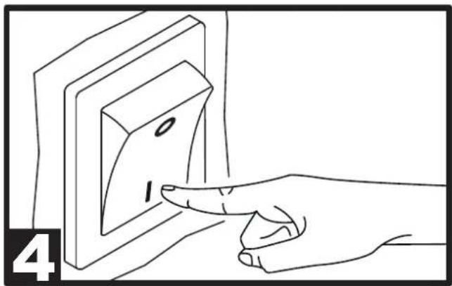
▶6.1.5. Take the “ON/OFF” switch to the “ON” (I) position (SEE FIG. 4). The heater should switch-on within a few seconds. If the heater does not start, consult the “13. TROUBLESHOOTING” paragraph. MODELS WITH A DOUBLE COMBUSTION CHAMBER: To use the heater at maximum power turn both “ON/OFF” switches to “ON” (I). To use the heater at intermediate power turn only one of the “ON/OFF” switches to “ON” (I). Indications for managing and selecting ignition of the single chamber are on the control panel and on the combustion chamber.
▶6.1.6. For the models with room thermostat, check the position of the knob (SEE FIG. 9-10).
N.B.: IF THE HEATER SHOULD SWITCH-OFF DUE TO THE LACK OF FUEL, TOP-UP THE TANK AND RESET THE HEATER (SEE PAR. 6.2).
▶▶6.2. RESETTING THE HEATER:
In the models with automatic "RESET", switch the heater off and back on again (SEE FIG. 5-4).
▶▶6.3. SWITCHING THE HEATER OFF:
DO NOT PULL THE PLUG OUT UNTIL THE COOLING CYCLE HAS TOTALLY ENDED.
▶6.3.1. Take the “ON/OFF” switch to the “OFF” (O) position (SEE FIG. 5).
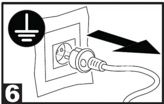
▶6.3.2. Disconnect the heater from the mains electricity (SEE FIG. 6).
7. REGULATING THE PRESSURE OF THE COMPRESSOR (Contact the technical service center)
(SEE FIG. 7)
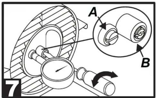
THE COMPRESSOR PRESSURE MAY HAVE TO BE RESTORED WITH WEAR OF THE HEATER.
▶7.1. Use the "TECHNICAL DATA TABLE" to identify the correct pressure (Bar - PSI - kPa) of your heater.
▶7.2. Remove the screw/cap of the manometer connection (A).
▶7.3. Assemble the manometer (not supplied, see "ACCESSORIES").
▶7.4. Switch the heater on.
▶7.5. Act on the regulation screw by turning it clockwise to increase the pressure and anticlockwise to decrease it (B).
▶7.6. Remove the manometer and restore the screw/cap (A).
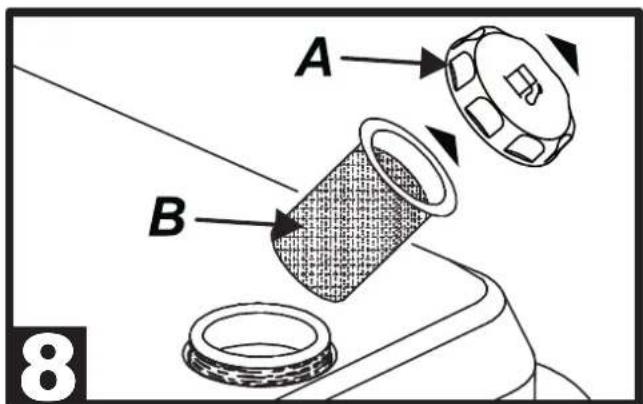
8. CLEANING THE TANK FILTER
(SEE FIG. 8)
DEPENDING ON THE QUALITY OF THE FUEL THAT IS USED, THE TANK FILTER MAY HAVE TO BE CLEANED.
▶8.1. Remove the cap (A) from the tank.
▶8.2. Extract the filter (B) from the tank.
▶8.3. Clean the filter (B) with clean fuel, paying attention not to damage it.
▶8.4. Re-mount the filter (B) in the tank.
▶8.5. Close the cap (A).
9. PRESERVATION AND
TRANSPORT
I ORDER TO KEEP AND/OR TRANSPORTAR THE HEATER IN THE BEST WAY, STHE FOLLOWING PROCEDURE MUST BE FOLLOWED.
▶9.1. Empty the fuel tank (some models have a draining cap on the bottom of the tank. In
this case, remove the drain cap and empty the fuel).
▶9.2. If the presence of residues is noted, pour clean fuel into the tank and drain off again.
▶9.3. Close the tank cap and/or the draining cap and dispose of the fuel appropriately according to the Standards in force.
▶9.4. In order to keep the heater in the best way possible, it must be kept on a level surface to prevent the escape of fuel and in a dry place away from any possible external threats.
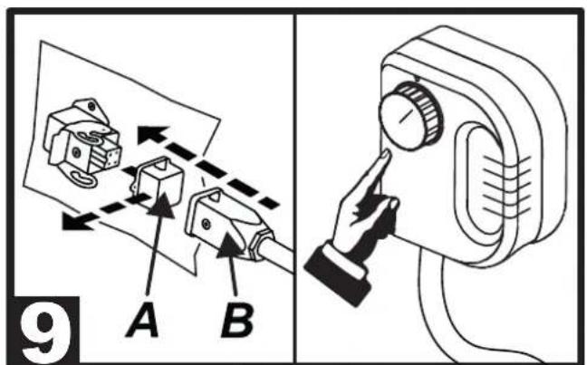
10. ROOM THERMOSTAT
▶▶10.1. MODELS PRE-SET FOR REMOTE ROOM THERMOSTAT:
(SEE FIG. 9)
For models preset for remote room thermostat, remove the cover connected to the heater (A), connect the thermostat (B) (optional) and set the desired room temperature. The room thermostat completely turns off the heater once the set temperature has been reached. If the temperature drops below the set temperature, the heater will automatically turn itself on again.
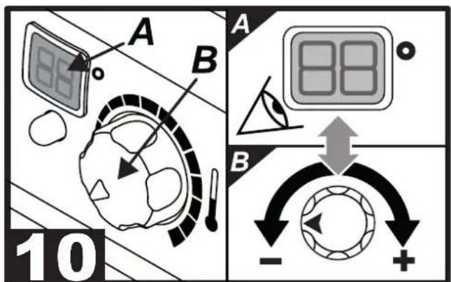
▶▶10.2. MODELS WITH ROOM
THERMOSTAT INSTALLED ON THE CONTROL PANEL:
(SEE FIG. 10)
For models with room thermostat installed on the control panel, when the knob (B) is turned the desired temperature starts flashing on the display (A) for a few seconds, after which the display shows the room temperature. When the knob (B) is turned completely to the right, the display (A) shows “CH”, after which the heater works continuously.
▶▶10.3. MODELS PRE-SET FOR REMOTE ROOM THERMOSTAT AND ROOM THERMOSTAT INSTALLED ON THE CONTROL PANEL:
(SEE FIG. 9-10)
For models preset for remote room thermostat and room thermostat installed on the control panel, remove the cover connected to the heater (SEE A FIG. 9) and connect the thermostat (SEE B FIG. 9) (optional). For correct heater operation, completely turn the knob to the right (SEE B FIG. 10), the display (SEE A FIG. 10) shows "CH", after which set the desired temperature on the remote room thermostat.
11. PREVENTIVE MAINTENANCE SCHEDULE
WARNING: BEFORE PERFORMING ANY MAINTENANCE OR REPAIRS, DISCONNECT THE POWER SUPPLY CABL FROM THE MAINS AND MAKE SURE THAT THE HEATER IS COLD.
| Fuel tank Empty and rinse the tank with clean fuel every 150-200 working hours | Empty and rinse the tank with clean fuel (SEE PAR. 9) |
| Filters Clean or replace every 500 working hours or when necessary | Contact the technical service center |
12. DISPLAY ERRORS (WHERE PRESENT)
(SEE FIG. 10)
| CAUSE SOLUTION | ||
| F0 | 1. The “ON/OFF” switch is turned “ON” (I) when the heater is plugged in | 1. After disconnecting the heater, see that the switch is in the “OFF” (0) position, plug the heater in and turn the switch “ON” (I) |
| F1 | 1. No fuel2. Fuel is contaminated3. Photocell is dirty or damaged4. Fuel filter is dirty5. Ignition error | 1. Turn the switch “OFF” (0), refill the fuel tank2. Turn the switch “OFF” (0) empty and refill the fuel tank. Clean the filter using clean fuel, do not damage the filter (SEE PAR. 8)3. Contact the technical service center4. SEE PAR. 85. Contact the technical service center |
| F2 | 1. Interrupted cable2. Sensor is damaged | 1. Contact the technical service center2. Contact the technical service center |
| F3 | 1. Internal heater overheating 1. Turn the heater off, wait until it is cooled down | |
| F4 | 1. Incorrect voltage 1. Check voltage of your electric supply system | |
| LO | 1. External temperature below -5°C 1. Normal condition | |
| CH | 1. Continuous operation 1. Normal condition | |
13. TROUBLESHOOTING
| PROBLEM | POSSIBLE CAUSE POSSIBLE | SOLUTION |
| The heater does not start | 1. Generator blocked2. Starter switch in “OFF” position (0)3. No power supply4. Temperature sensor override5. Control card blocked6. Incorrect setting of the room thermostat (where present) | 1. Reset the heater (SEE PAR. 6.2)2. Take the “ON/OFF” switch to the “ON” (I) position3. Insert the power supply cable into the mains socket correctly4. Wait at least ten minutes then try to run ignition again5a. Reset the heater (SEE PAR. 6.2)5b. Identify the display error (where present)6. Act on the room thermostat, taking it to a higher temperature than that of the work environment (SEE FIG. 9-10) |
| The motor starts but the flame is not triggered | 1. No fuel2. Incorrect pump pressure3. Presence of foreign substances in the tank | 1. Top-up fuel and reset the heater2. Regulate the pressure of the compressor (SEE PAR. 7)3. Empty and fill the tank with clean fuel (SEE PAR. 9) |
IMPORTANTE: LEGGERE E COMPRENDERE QUESTO MANUALE OPERATIVO PRIMA DI EFFETTUARE L'ASSEMBLAGGIO, LA MESSA IN FUNZIONE O LA MANUTENZIONE DI QUESTO RISCALDATORE. L'USO ERRATO DEL RISCALDATORE PUÒ CAUSARE LESIONI GRAVI. CONSERVARE QUESTO MANUALE A TITOLO DI FUTURO RIFERIMENTO.
▶▶6.2. RESET DEL RISCALDATORE:
▶▶6.2. REMISE A ZERO DU GENERATEUR:
▶▶6.3. ARRET DU GENERATEUR:
NE PAS DÉBRANCHER LA PRISE JUSQU'À CE QUE LE CYCLE DE REFROIDISSEMENT SOIT TERMINÉ.
PROBLEME CAUSE POSSIBLE SOLUTION POSSIBLE
▶▶6.2. RESET AF APPARATET:
I HENHOLD TIL BRÆNDSTOFFETS KVALITET, DER ER I BRUG, KAN DET VÆRE N∅DVENDIGT AT RENG∅RE TANKENS FILTER.
▶8.1. Fjerne tankens prop (A).
▶8.2. Fjerne filtret (B) fra tanken.
▶8.3. Rengøre filtret (B) med rent brændstof, med stor omhu, for at undgå at beskadige den.
▶8.4. Montere filtret (B) i tanken igen.
▶8.5. Lukke proppen (A).
9. OPBEVARELSE OG TRANSPORT
FOR AT OPBEVARE OG/ELLER TRANSPORTERE GENERATOREN, TILRÅDES DET AT GÅ FREM SOM F∅LGENDE.
▶▶6.3. SLUKKING AV GENERATOR:
IKKE KOBLE FRA KONTAKTEN F∅R
AVKJ∅LINGSSYKLUSEN ER FULLF∅RT.
TA INTE UT KONTAKTEN FÖRRÄN KYLCYKELN HAR FULLBORDATS.
▶6.1. WŁĄCZENIE NAGRZEWNICY:
▶▶6.2. RESET NAGRZEWNICY:
▶6.3. WYŁĄCZENIE NAGRZEWNICY:
NIE ODŁĄCZAĆ WTYCZKI PRZEWODU ZASILAJĄCEGO AŻ DO ZAKOŃCZENIA CYKLU CHŁODZENIA.
▶▶6.1. GENERATORA IESLĚGŠANA:
natural_image
Line drawing of a manual lawn mower with wheels and handle (no text or symbols)WHEELS AND HANDLE KIT - KIT RUOTE E MANIGLIA - SATZ RÄDER UND TRAGEGRIFF - KIT DE RUEDAS Y MANIJA - KIT ROUES ET POIGNEE - KIT WIELEN EN HANDVAT - KIT RODAS E ALÇA - KIT MED HJUL OG HÄNDTAG - PYÖRÄ- JA KAHVASARJA - SETT MED HJUL OG HÄNDTAK - SATS MED HJUL OCH HANDTAG - ZESTAW KÓŁEK I UCHWYT - НАБОР КОЛЕС И РУЧЕК - SOUPRAVA KOLEČEK A RUKOJETÍ - KERÉK ÉS FOGÓKÉSZLET - KOMPLET KOLES IN ROČAJA - TEKERLEKLER VE KULP KÍTÍ - GARNITURA KOTAČA I RUČICE - RATUKÚ IR RANKENÚ RINKINYS - RITENU UN ROKSTURA KOMPLEKTS - RATASTE JA KÄEPIDEMETE KOMPLEKT - KIT ROTI ŞI MÄNER - SADA KOLIESOK A RUKOVÄTÍ - KOMПЛЕКТ КОЛЕЛА И РЪКАХВАТКА - KOMПЛЕКТ КОЛІС I РУЧКИ - KOMPLET TOČKOVA I RUČKA - KIT TРОХΩΝ ΚΑΙ XΕΙΡΟΛΑΒΗΣ - 轮子和把手包 - ДОНГЕЛЕКТЕРІ ЖЭНЕ HANDLE KIT
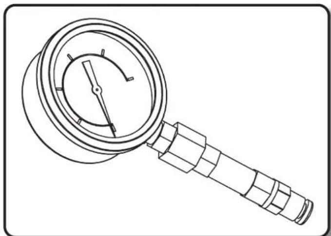
natural_image
Line drawing of a magnifying glass with a handle and dial (no text or symbols)MANOMETER - MANOMETRO - MANOMETER - MANÓMETRO - MANOMETRE - MANOMETER - MANÓMETRO - MANOMETER - PAINEMITTARI - MANOMETER - MANOMETER - MANOMETR - MAHOMETP - MANOMETR - MANOMÉTER - MANOMETER - MANOMETRE - MANOMETAR - MANOMETRAS - MANOMETRS - MANOMEETER - MANOMETRU - MANOMETER - MAHOMETB.P - MAHOMETP - MANOMETAR - MANOMETPO - 气压表 - MAHBMETP
natural_image
Line drawing of a portable electrical control unit connected to a multi-wire cable (no text or symbols)ROOM THERMOSTAT - TERMOSTATO AMBIENTE - RAUMTHERMOSTAT - TERMOSTATO AMBIENTE - THERMOSTAT D'AMBIANCE - OMGEVINGSTHERMOSTAAT - TERMÓSTATO AMBIENTE - MILJ∅TERMOSTAT - HUONETERMOSTAATTI - ROMTERMOSTAT - RUMSTERMOSTAT - STEROWNIK POKOJOWY - KOMHATHBÍI TEPMOCTAT - TERMOSTAT PROSTŘEDÍ - SZOBATERMOSZTÁT - SOBNI TERMOSTAT - ODA TERMOSTATI - AMBIJENTALNI TERMOSTAT - APLINKOS TERMOSTATAS - VIDES TERMOSTATS - RUUMITERMOSTAAT - TERMOSTAT DE MEDIU ÍNCONJURĂTOR - TERMOSTAT PROSTREDIA - CTAEH TEPMOCTAT - TEPMOCTAT ТЕМПЕРАТУРИ ЗОВНІШНЬОГО СЕРЕДОВИЩА - AMBIJENTALNI TERMOSTAT - ОЕРМОΣΤΑΤΗΣ ХОРОУ - 温控器 - БӨЛМЕ ТЕРМОСТАТЫ
NOTE:
CE CONFORMITY CERTIFICATE
CE
CE CONFORMITY CERTIFICATE - DICHIARAZIONE DI CONFORMITÀ CE - EG-KON-FORMITÄTSERKLÄRUNG - DECLARACIÓN DE CONFORMIDAD CE - DECLARATION DE CONFORMITE CE - EG-CONFORMITEITVERKLARING - DECLARAÇÃO DE CONFORMIDA-DE CE - EU-OVERENSSTEMMELSESERKLÆRING - EY-VAATIMUSTENMUKAISUUSVA-KUUTUS - CE-SAMSVARSERKLÆRING - EG-FÖRSÄKRAN OM ÖVERENSSTÄMMELSE - DEKLARACJA ZGODNOŚCI WE - ДЕКЛАРАЦИЯ О COOTBETCTВИИ CE - PROHLÁŠENÍ O SHODĚ CE - EK MEGFELELŐSÉGI NYILATKOZAT - IZJAVA O SKLADNOSTI IN OZNAKA CE - CE UYGUNLUK BEYANI - IZJAVA CE O SUKLADNOSTI - ES ATITIKTIES DEKLARACIJA - EK ATBILSTĪBAS - DEKLARĀCIJA - EÜ VASTAVUSDEKLARATSIOON - DECLARAȚIE DE CONFORMITATE CE - PREHLÁSENIE O ZHODE CE - ДЕКЛАРАЦИЯ ЗА СЪВМЕСТИМОСТ CE - ДЕКЛАРАЦИЯ ВІДПОВІДНОСТИ CE - IZJAVA CE O PRIKLADNOSTI ΔΗΛΩΣΗ ΣΥΜΜΟΡΦΩΣΗΣ CE - CE 符合性声明
DANTHERM S.p.A. Via Gardesana 11, -37010- Pastrengo (VR), ITALY
Product: - Prodotto: - Produkt: - Producto: - Produit: - Product: - Produkt: - Tuote: - Produkt: - Produkt: - Produkt: - Изделие: - Výrobek: - Termék: - Izdelek: - Ürün: - Proizvod: - Gaminys: - Ieríce: - Toode: - Produsul: - Výrobok: - Продукт: - Виріб: - Proizvod: - Проїóv: - 产品:
Stefano Verani (Member of the Board)
| UKCA CONFORMITY CERTIFICATE | UKCA |
| UKCA CONFORMITY CERTIFICATE | |
| DANTHERM S.p.A. Via Gardesana 11, -37010- Pastrengo (VR), ITALYProduct: | |
| B 35CEL - B 65CEL - B 95CEL - B 145CELB 35CED - B 70CED - B 100CED - B 150CED - B 300CEDB 35CEG - B 70CEG - B 100CEG - B 150CEG | |
| We declare that it is compliant with:2014/30/EU, 2014/35/EUBS EN 62233:2008, BS EN 61000-3-2:2014, BS EN 61000-3-3:2013,BS EN 55014-1:2017+A11:2020, BS EN 55014-2:2015, BS EN 60335-1:2012+A2:2019, BS EN 60335-2-102:2006+A2:2016 | |
| Pastrengo, 2022Stefano Verani (Member of the Board) | |
UKCA CONFORMITY CERTIFICATE
UK CA
NOTE:
▶ en - DISPOSAL OF THE PRODUCT
-This product has been designed and manufactured with top-quality materials and components, which can be re-cycled and re-used. -When a crossed-wheely bin symbol is attached to the product, it means that the product is protected by the, 2012/19/UE European Directive.
-Please obtain information regarding the local differentiated collection system for electrical and electronic products.
-Respect local Standards in force and do not dispose of old products as normal domestic waste. Correct disposal of the product helps to prevent possible negative consequences for health, the environment and mankind.
▶pl - UTYLIZACJA PRODUKTU
▶ Iv - PRODUKTA IZNÍCINÁŠANA
natural_image
Abstract geometric composition with yellow and black blocks (no text or symbols)Dantherm S.p.A.
Via Gardesana 11
37010 Pastrengo (VR)
Italy
t.: +39 045 6770533
e.: info.it@danthermgroup.com

DOWNLOAD CATALOGUE

SEND US YOUR FEEDBACK

REGISTER FOR 3-YEARWARRANTEE