Fusaro EFS130BL - Basket ELICA - Free user manual and instructions
Find the device manual for free Fusaro EFS130BL ELICA in PDF.

User questions about Fusaro EFS130BL ELICA
0 question about this device. Answer the ones you know or ask your own.
Ask a new question about this device
Download the instructions for your Basket in PDF format for free! Find your manual Fusaro EFS130BL - ELICA and take your electronic device back in hand. On this page are published all the documents necessary for the use of your device. Fusaro EFS130BL by ELICA.
USER MANUAL Fusaro EFS130BL ELICA
Installation Instructions Guide
natural_image
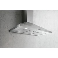
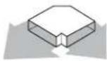
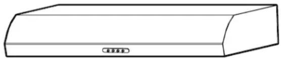
Simple line drawing of a rectangular object with two circular indentations on top (no text or symbols)MODEL EFS130
natural_image
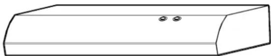
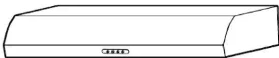
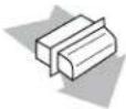
Simple line drawing of a rectangular box with a curved top and a small circular label on the side (no text or symbols)MODELS ENM230 ENM236
APPROVED FOR RESIDENTIAL APPLIANCES FOR RESIDENTIAL USE ONLY READ AND SAVE THESE INSTRUCTIONS
PLEASE READ ENTIRE INSTRUCTIONS BEFORE PROCEEDING. INSTALLATION MUST COMPLY WITH ALL LOCAL CODES.
IMPORTANT: Save these Instructions for the Local Electrical Inspector's use. INSTALLER: Please leave these Instructions with this unit for the owner. OWNER: Please retain these instructions for future reference.
Safety Warning: Turn off power circuit at service panel and lock out panel before wiring this appliance. Requirement 120 VAC, 60 Hz. 15 or 20 A Branch Circuit
IMPORTANT SAFETY INSTRUCTIONS
WARNING: TO REDUCE THE RISK OF FIRE, ELECTRIC SHOCK, OR INJURY TO PERSONS, OBSERVE THE FOLLOWING:
■ Use this unit only in the manner intended by the manufacturer. If you have questions, contact the manufacturer.
Before servicing or cleaning the unit, switch power off at service panel and lock the service disconnecting means to prevent power from being switched on accidentally. When the service disconnecting means cannot be locked, securely fasten a prominent warning device, such as a tag, to the service panel.
■ Installation work and electrical wiring must be done by qualified person(s) in accordance with all applicable codes and standards, including fire-rated construction.
■ Do not operate any fan with a damaged cord or plug. Discard fan or return to an authorized service facility for examination and/or repair.
- Sufficient air is needed for proper combustion and exhausting of gases through the flue (chimney) of fuel burning equipment to prevent backdrafting. Follow the heating equipment manufacturer's guideline and safety standards such as those published by the National Fire Protection Association (NFPA), the American Society for Heating, Refrigeration and Air Conditioning Engineers (ASHRAE), and the local code authorities.
■ When cutting or drilling into wall or ceiling; do not damage electrical wiring and other utilities.
■ Ducted fans must always be vented outdoors.
CAUTION: For general ventilating use only. Do not use to exhaust hazardous or explosive materials and vapors.
CAUTION: To reduce risk of fire and to properly exhaust air, be sure to duct air outside - do not vent exhaust air into spaces within walls or ceilings, attics or into crawl spaces, or garages.
WARNING: TO REDUCE THE RISK OF FIRE, USE ONLY METAL DUCTWORK
WARNING: TO REDUCE THE RISK OF A RANGE TOP GREASE FIRE:
■ Never leave surface units unattended at high settings. Boilovers cause smoking and greasy spillovers that may ignite. Heat oils slowly on low or medium settings.
■ Always turn hood ON when cooking at high heat or when flambeing food
(i.e. Crepes Suzette, Cherries Jubilee, Peppercorn Beef Flambé).
■ Clean ventilating fans frequently. Grease should not be allowed to accumulate on fan or filter.
■ Use proper pan size. Always use cookware appropriate for the size of the surface element.
WARNING: TO REDUCE THE RISK OF INJURY TO PERSONS IN THE EVENT OF A RANGE TOP GREASE FIRE, OBSERVE THE FOLLOWING:"
■ SMOTHER FLAMES with a close fitting lid, cookie sheet, or metal tray, then turn off the burner. BE CAREFUL TO PREVENT BURNS. If the flames do not go out immediately, EVACUATE AND CALL THE FIRE DEPARTMENT.
■ NEVER PICK UP A FLAMING PAN - you may be burned.
■ DO NOT USE WATER, including wet dishcloths or towels - a violent steam explosion will result.
■ Use an extinguisher ONLY if:
- You know you have a class ABC extinguisher, and you already know how to operate it.
- The fire is small and contained in the area where it started.
- The fire department is being called.
- You can fight the fire with your back to an exit.
^a Based on "Kitchen Fire Safety Tips" published by NFPA.
WARNING: To reduce the risk of fire or electrical shock, do not use this fan with any solid-state speed control device.
READ AND SAVE THIS INSTRUCTIONS
LOCATION REQUIREMENTS
IMPORTANT: Observe all governing codes and ordinances
It is the installer's responsibility to comply with installation clearances specified on the model/serial rating plate. The model/serial rating plate is located inside the range hood on the left wall.
■ Range hood location should be away from strong draft areas, such as windows, doors and strong heating vents.
■ Cabinet opening dimensions that are shown must be used. Given dimensions provide minimum clearance. Consult the cooktop/range manufacturer installation instructions before making any cutouts.
■ Grounded electrical outlet is required. See "Electrical Requirements" section.
■ All openings in ceiling and wall where range hood will be installed must be sealed
■ These range hoods are factory set for vented installations.
Models that are capable of being installed as non-vented (recirculating) require charcoal filters. See the "Accessories" section to order recirculation kit.
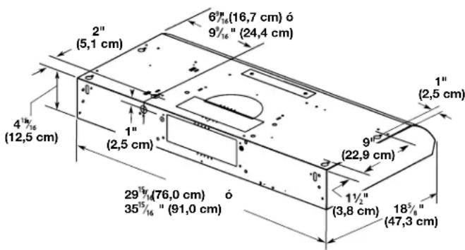
PRODUCT DIMENSIONS
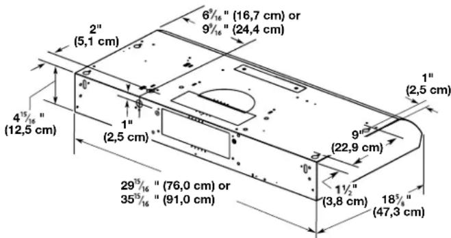
text_image
2" (5,1 cm) 6⁹/₁₆" (16,7 cm) or 9⁹/₁₆" (24,4 cm) 1" (2,5 cm) 4¹⁵/₁₆" (12,5 cm) 1" (2,5 cm) 9" (22,9 cm) 29⁵/₁₆" (76,0 cm) or 35⁵/₁₆" (91,0 cm) 1½" (3,8 cm) 18⁵/₁₆" (47,3 cm)INSTALLATION CLEARANCES
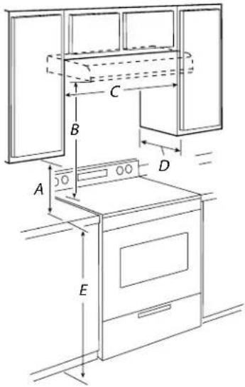
text_image
Technical diagram of a kitchen appliance with labeled dimensions A, B, C, D, E and internal componentsA. 18" (45.7cm) min. clearance - upper cabinet to counterto
B. 24" (61 cm) suggested min.- bottom of range hood to cooking surface.
C. 30" (76.2cm) min. cabinet opening width for 30" (76.2cm) models and 36" (91.4cm) min. cabinet width for 36" (91.4cm) models. D. 13"(33cm) cabinet depth. E. 36" (91.4 cm) base cabinet height.
VENTING REQUIREMENTS
■ Vent system must terminate to the outdoors, except for no vented (recirculating) installations.
■ Do not terminate the vent system in an attic or other enclosed area.
■ Do not use a 4" (10.2 cm) laundry-type wall cap.
■ Use a 7" (17.8 cm) round metal vent or a 4" x 10" (8.3 x 25.4 cm) rectangular metal vent, depending on your model. Rigid metal vent is recommended. Plastic or metal foil vent is not recommended.
■ The length of vent system and number of elbows should be kept to a minimum to provide efficient performance.
For the most efficient and quiet operation:
■ Use no more than three 90° elbows.
■ Make sure there is a minimum of 24" (61 cm) of straight vent between the elbows if more than 1 elbow is used.
■ Do not install 2 elbows together.
■ Use clamps to seal all joints in the vent system.
■ The vent system must have a damper. If roof or wall cap has a damper, do not use damper supplied with the range hood.
■ Use caulking to seal exterior wall or roof opening around the cap.
Cold Weather Installations
An additional back draft damper Non return valve should be installed to minimize backward cold air flow and a thermal break should be installed to minimize conduction of outside temperatures as part of the vent system. The damper Non return valve should be on the cold air side of the thermal break.
The break should be as close as possible to where the vent system enters the heated portion of the house.
Venting Methods
Vent system can terminate either through the roof or wall. Use 314 " x 10" (8.3 x 25.4 cm) rectangular with a maximum vent length of 35 ft (10.7 m) or 7" (17.8 cm) or larger round vent with a maximum length of 50 ft (15.2 m) for vent system.
NOTE: Flexible vent is not recommended. Flexible vent creates back pressure and air turbulence that greatly reduces performance.
text_image
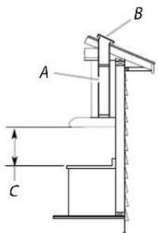
A B CRoof Venting
A. 7" (17.8 cm) round vent out the top and through the wall (purchased separately).
3¼"x 10" (8.3 x 25.4 cm) rectangular vent through the wall or out the top (purchased separately).
B. Roof cap (purchased separately)
C. 24" (61.0 cm) min. above the cooking surface.
TOOLS AND PARTS
Gather the required tools and parts before starting installation. Read and follow the instructions provided with any tools listed here.
| RANGE HOOD MODELS | |||
| EFS130 | ENM230 ENM236 | ||
| SUPPLIED PARTS | 4 - 4.5X13 screws | √ | √ |
| T-10 torx adapter | √ | √ | |
| 2 - 3.5x5 screws | √ | √ | |
| 3/4"x10" (8.3 x 25.4cm) rectangular vent connector. | √ | ||
| 3/4"x10" (8.3 x 25.4cm) rectangular vent connector with damper no return valve | √ | ||
| PARTS NEEDED | 3 - UL listed wire connector | √ | √ |
| wall / roof cap to match the vent system | √ | √ | |
| 1 - 75W max, 120V incandescent light bulb. | √ | ||
| 2 - 40W max, 120V halogen lamps | √ | ||
| 3/4" x 10" (8.3 x 25.4 cm) rectangular metal vent system | √ | √ | |
| 3/4" (8.3 cm) rectangular damper No return valve (optional). Accessories part No. EXNRVRT | √ | ||
| 7" (17.8 cm) round metal vent system | √ | ||
| 7" (17.8 cm) round vent mounting plate. Accessories part. No. EXXTRK07 | √ | ||
| 7" (17.8 cm) round damper non return valve (optional). Accessories part No. EXX-NRVRD | √ | ||
| Recirculation kit. part No. ENMRCK36 | √ | ||
| For cabinets with recessed bottoms | Two 2" (5.1 cm) wide filler strips. Length and thickness determined by recess dimensions. | ||
| Four flat head wood screws or machine screws with washers and nuts (to attach filler strips). | |||
| TOOLS NEEDED(all models) | Drill weatherproof caulking compound% (3.0 cm) drill bit% (3.0 mm) drill bit for pilot holesPencil Wire stripper or utility knife Tape measure or ruler | ■ Caulking gun and weatherproof caulking compoundFlat-blade screwdriver Phillips screwdriver Saber or keyhole saw Metal snips Compass or 8" (20.3 cm) circle template | |
text_image
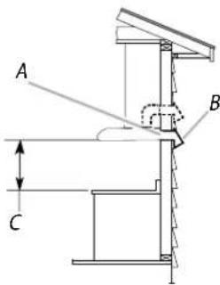
A B CWall Venting
A. 7" (17.8 cm) round vent out the top and
through the wall (purchased separately).
3¼"x 10" (8.3 x 25.4 cm) rectangular vent through the wall or out the top (purchased separately).
B. Wall cap (purchased separately)
C. 24" (61.0 cm) min. above the cooking surface.
CALCULATING VENT SYSTEM LENGTH
To calculate the length of the system you need, add the equivalent feet (meters) for each vent piece used in the system.
7" (17.8 cm) Round Vent System
| Vent piece: 45° elbowLength: 2.5 ft (0.8m) | Vent piece: 90° elbowLength: 1.5 ft (0.8m) | Vent piece: 7" (17.8cm)wall capLength: 0.0 ft (0.0m) | |
 |  |  | |
| Vent piece: 31⁄4" x 10" (8.3 cm x 25.4cm), 4.5 ft to 7" (17.8 cm)Length: 4.5 ft (1.4m) | Vent piece: 31⁄4" x 10" (8.3 cm x 25.4cm), to 7" (17.8 cm) 90° elbowLength: 5.0 ft (1.5m) | ||
 |  | ||
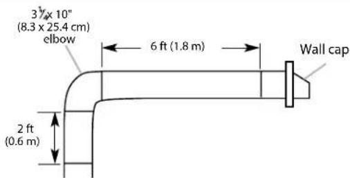
Example Vent System
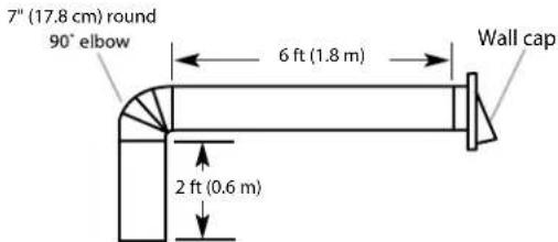
text_image
7" (17.8 cm) round 90° elbow 6 ft (1.8 m) Wall cap 2 ft (0.6 m)Maximum Recommended Length = 50 ft (15.2 m)
| 1 - 90° elbow = 5.0 ft (1.5 m) |
| 1 - wall cap = 0.0 ft (0.0 m) |
| 8 ft (2.4 m) straight = 8.0 ft (2.4 m) |
Length of 7" (17.8 cm) system = 13.0 ft (3.9 m)
3¼" x 10" (8.3 cm x 25.4 cm) Vent System
| Vent piece: 90° elbowLength: 5.0 ft (1.5m) | Vent piece: 90° elbowLength: 12.0 ft (3.7m) | Vent piece: 31⁄4" x 10" wall capLength: 0.0 ft (0.0m) |
 |  |  |
Example Vent System
text_image
3" x 10" (8.3 x 25.4 cm) elbow 6 ft (1.8 m) Wall cap 2 ft (0.6 m)Maximum Recommended Length = 35 ft (10.7 m)
| 1 - 90° elbow = 5.0 ft (1.5 m) |
| 8 ft (2.4 m) straight = 8.0 ft (2.4 m) |
| 1 - wall cap = 0.0 ft (0.0 m) |
Length of 3 14 " x 10" = 13.0 ft (3.9 m)
(8.3 cm x 25.4 cm) system
BEFORE INSTALLING THE HOOD
Recommended mounting height is 24" from the bottom of the range hood to the top of the cooking surface.
The hood should be mounted to the bottom of a standard wall cabinet. If the hood must be mounted directly to a wall, secure the hood to wall studs.
All wiring must comply with local codes and the unit must be properly grounded. The hood is connected to a 110 - 120 VAC lighting circuit (15 Amp) in the circuit breaker or fuse box.
The model EFS130 is ducted
The models ENM230 and ENM236 are convertible (they may be installed as a ducted or as a non-ducted unit).
If the range hood is to be non - ducted:
Purchase Accessories Recirculation (non ducted) kit ENM230 / ENM236: ENMRCK36
If the range hood is to be ducted:
- Ductwork can be installed vertically or horizontally.
- Duct runs should be as short as possible.
■ Avoid the use of elbows.
■ Use duct tape at all joints.
■ Do not use duct smaller than the discharge on the hood.
■ For 7" round ductwork installation, purchase accessory transition Kit:
- 7" (17.8 cm) round vent mounting plate.
Accesories Part No. EXXTRK07 (purchased separately). - 7" (17.8 cm) round damper Non return valve.
Accesorie Part No. EXXNRVRD (purchased separately).
■ For 3½" x 10" (8.3 x 25.4 cm) rectangular ductwork installation:
- 3 14 × 10^9 (8.3 x 25.4 cm) rectangular vent conector is supplied.
- If needed purchase 3¼" x 10" (8.3 x 25.4 cm) rectangular damper non return valve. Accessories Part No. EXXNRVRT.
INSTALLATION INSTRUCTIONS
Horizontal discharge through wall
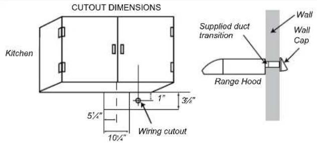
text_image
CUTOUT DIMENSIONS Kitchen 5½" 10½" Wiring cutout 1" 3½" Supplied duct transition Wall Wall Cap Range HoodVertical discharge using 3 ^1/4 " x 10" duct
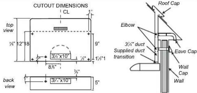
text_image
CUTOUT DIMENSIONS CL top view 7/8" 12" 18" 2" 3/4"x10" ½" 1½"1" 8/8" back view 1" 3/4"x10" 5" 9" 3/4" duct Supplied duct transition Elbow Roof Cap Eave Cap Wall Cap WallVertical discharge using 7" round duct
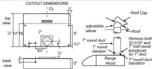
text_image
CUTOUT DIMENSIONS CL top view 7/8" 12" 18 7" 2" 5" 9" 1½" 8½" 7/8" back view 1" 5" Roof Cap adjustable elbow Roof 7" round duct Remove both 3/4"x10" and 7" half round knockouts for 7" duct Range Hood 7" round duct transition- Lift the range hood up under cabinet and determine final location by centering beneath cabinet. Mark on the underside of cabinet the location of the 4 keyhole mounting slots on the range hood. Set range hood aside on a covered surface.
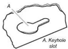
text_image
A A. Keyhole slot- Use 18 " (3 mm) drill bit and drill 4 pilot holes as shown.

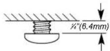
- Install the 4 - 4.5 mm x 13 mm mounting screws in pilot holes. Leave about 14 " (6.4 mm) space between screw heads and cabinet to slide range hood into place.
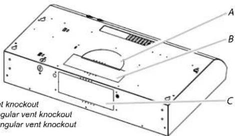
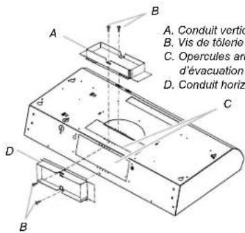
- Remove transition knockouts depending on your model. Round vent system installations - Remove top rectangular and round vent knockouts. Rectangular vent system installations - For roof installations, remove the top rectangular vent knockout. For wall installations, remove the rear rectangular vent knockout Non-ducted (recirculating) installations - Do not remove any knockouts.
text_image
st knockout angular vent knockout angular vent knockoutA. Round vent knockout
B. Top rectangular vent knockout
C. Rear rectangular vent knockout
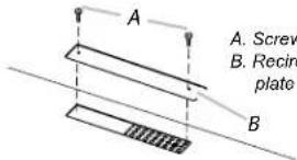
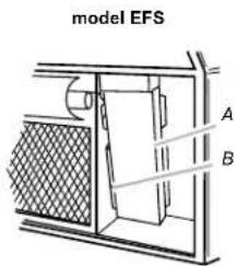
- Remove metal grease filters. See the "Range Hood Care" section. For the ENM series models, first remove the lateral panels. NOTE: You will have 3¼" x 10" (8.3 x 25.4 cm) rectangular vent connector inside your range hood. Some models are recirculation (non-ducted only) and will not have vent connector

text_image
Model EFS: A. Screws B. 3¼" x 10" (8.3x24.4cm) rectangular vent knockout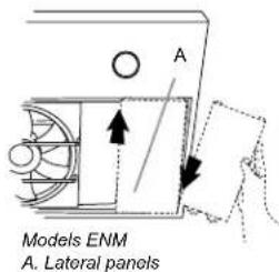
text_image
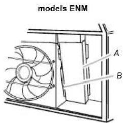
Models ENM A. Lateral panels-
Remove the 314 x 10^ (8.3 x 25.4 cm) rectangular vent connector attached with screws or taped on the inside your range hood.
-
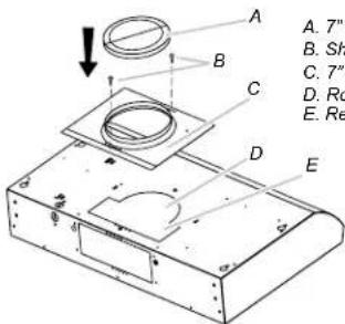
For round installation: Install 7" (17.8 cm) round vent mounting plate and damper or 3¼" x 10" (8.3 x 25.4 cm) vent connector, depending on your vent system installation. (Purchase as an accesory).
text_image
A. 7" B. Sh C. 7" D. Ro E. ReNOTE: The 3¼" x 10" (8.3 x 25.4 cm) rectangular vent connector can be installed up to 1" (2.5 cm) on either side of the hood center to accommodate off center ductwork.
A. 7" (17.8cm) round damper
B. Sheetmetal screws
C. 7" (17.8cm) round vent mounting plate
D. Round vent knockout
E. Rectangular vent knockout
text_image
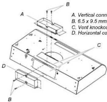
A. Vertical conn B. 6,5 x 9,5 mm C. Vent knockout D. Horizontal coIf a vent damper is installed with a wall cap with damper, check to make sure they do not interfere with each other. Remove the vent connector damper flap if they interfere. Non-ducted (recirculating) installations - No vent attachments. The ENM230 and ENM236 series models requires the removal of the recirculation cover plate. Remove the two screws from the recirculation cover plate and remove.
text_image
A. Screw B. Recirc plate BPOWER SUPPLY CABLE INSTALLATION
-
For direct wire installations, run the home power supply cable according to the National Electric Code or CSA standards and local codes and ordinances. There must be enough wiring from the fused disconnect (or circuit breaker) box to make the connection in the hood electrical terminal box. For optional power supply cord kit installations, follow the instructions included with the power supply cord kit. NOTE: Do not reconnect power until the installation is complete.
-
Remove the screw from the terminal box cover. Remove terminal box cover and set aside.
text_image
model EFS A BA. Terminal box cover
B. Screw
text_image
models ENM A B- Remove the power supply knockout from the top or rear of the vent hood (depending on the incoming location of your home power supply cable) and install a UL Listed or CSA approved 12 " strain relief.
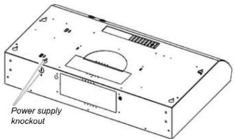
text_image
Power supply knockout- Using 2 or more people, lift the hood into final position. Feed enough electrical wire through the 12 UL listed or CSA approved strain relief to make connections in the terminal box. Tighten the strain relief screws.
- Position the range hood so that the large end of the keyhole slots are over the mounting screws. Then push the hood toward the wall so that the screws are in the neck of the slots. Tighten the mounting screws, making sure the screws are in the narrow neck of slots.
- Connect ventwork to hood. Seal joints with clamps to make secure and airtight.
- Check that back draft dampers work properly.
MAKE ELECTRICAL CONNECTION
WARNING
Electrical Shock Hazard Disconnect power before servicing. Replace all parts and panels before operating. Failure to do so can result in death or electrical shock.
- Disconnect power.
text_image
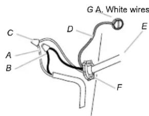
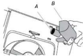
G A. White wires C D E A B FB. Black wires
C. UL listed wire connector
D. Green (or bare) ground wire
E. Home power supply cable
F. UL listed or CSA approved 12 " strain relief
G. Green ground screw
- Use UL listed wire connectors and connect white wires (A) together.
- Use UL listed wire connectors and connect black wires (B) together.
- Connect green (or bare) ground wire from power supply to green ground screw in terminal box. Be sure the ground wire is secured and the screw is well tight.
- Install terminal box cover.
- Reconnect power.
WARNING
Fire Hazard Electrically ground the blower. Use copper wire. Connect ground wire to green ground screw in terminal box. Failure to do so can result in death, fire, or electrical shock. Improper grounding can result in a risk or electrical shock. Consult a qualified electrician if the grounding instructions are not completely understood, or if doubt exists as to whether the appliance is properly grounded.
Complete Installation
- For the EFS130 series install the 75 W (max.) incandescent light bulb.
For the ENM230 and ENM236 series install the 40W (max) halogen lamps with G-9 base. See Range Hood Care section. - Replace grease filter if removed. See the "Range Hood Care" section.
- Check the operation of the range hood fan and light. See "Range Hood Control" section. If range hood does not operate, check to see whether a circuit breaker has tripped or a household fuse has blown. Disconnect power and check wiring connections.
NOTE: To get the most efficient use from your new range hood, Read the "Range Hood Control" section.
RANGE HOOD CONTROL
A. On / Off light switch
B. Fan speed switch
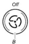
EFS130 Serie Model Control and features:
Operating the light
Push the light switch to the left to turn the light Off.
Push the light switch to the right to the turn the light On.
Operating the fan
Push the fan switch to the left for Low speed.
Push the fan switch to the right for High speed.
Push the fan switch to the middle for Off.
ENM230 and ENM236 Series Models Control and features
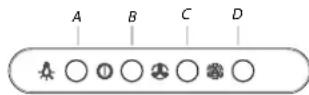
A. On / Off light button
B. Blower Off and Speed minimum button
C. Blower speed medium button
D. Blower speed maximum button
Operating the light
The On/Off light button controls both lights. Press once for On and again for Off.
Operating the fan
The BLOWER SPEED buttons turn the blower on and control the blower speed and sound level for quiet operation. The speed can be changed anytime during fan operation by pressing the desired blower speed button. Press the BLOWER OFF button a second time to turn the blower off.
RANGE HOOD CARE
CLEANING
IMPORTANT: Clean the hood and grease filters frequently according to the following instructions. Replace grease filter before operating the hood. Reinstall grease filter correctly and replace the screw in the vent system.
Exterior Surfaces:
IMPORTANT: Do not use soap-filled scouring pads, abrasive cleaners, Cooktop Polishing Creme, steel wool, gritty washcloths or paper towels. To avoid damage to the stainless steel, do not use cleaners that contain chlorine.
Cleaning Method:
■ Rub in direction of grain to avoid scratching or damaging the surface.
■ For stainless steel models, use a special stainless steel cleaner and polish.
■ Liquid detergent or all-purpose cleaner: Rinse with clean water and dry with soft, lint-free cloth.
■ Glass cleaner to remove fingerprints.
Metal Grease Filter (EFS Series Models)
For ducted installations:
- Remove screw from the grease filter retainer.
- Turn the grease filter retainer to release filter.
- Wash metal filters as needed in dishwasher or hot detergent solution.
- Reinstall the filter by placing the back edge in the channel at rear of hood.
Push filter into place, turn the filter retainer to secure filter to range hood. - Replace screw in the grease filter retainer
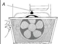
natural_image
Diagram of a fan or fan device with a mesh grille and central fan blade (no text or symbols)A. Filter retainer
For non-ducted (recirculation) installations:
The charcoal filter is not washable. It should last up to 6 months with normal use.
- Replace metal grease filter with a charcoal filter.
For information on ordering, see the "Accessories" section.
To replace filter:
- Remove screw from the grease filter retainer.
- Turn the grease filter retainer to release filter.
- Reinstall the filter by placing the back edge in the channel at rear of hood. Push filter into place, turn the filter retainer to secure filter to range hood.
- Replace screw in the grease filter retainer.
Metal Grease Filter (for ENM Series Models)
For ducted installations:
- Press the grease filter retainer to release filter.
- Wash metal filter as needed in dishwasher or hot detergent solution.
- Reinstall the filter by placing the back edge in the channel at rear of hood. Push filter into place, push down the filter retainer to secure filter to range hood.
text_image
A B CA. Halogen lights
B. Grease filter retainer
C. Grease filter
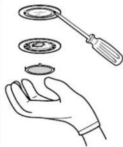
Replace the incandescent light bulb (EFS130 series models)
Turn off the range hood and allow the light bulb to cool.
- Disconnect power.
- Squeeze the plastic lens cover and remove it from the hood.
- Screw a new 120v 75W (maximum), A19 light bulb into socket.
- Replace lens cover by squeezing cover and inserting tabs into slots.
- Reconnect power.
- If new light does not operate, make sure the lamp is inserted correctly before calling service.
text_image
A BA. Light bulb socket (A19) B. Lens cover
Replace the halogen lamp (ENM230 & ENM236 series models)
Turn off the range hood and allow the halogen lamp to cool. To avoid damage or decreasing the life of the new bulb, do not touch bulb with bare fingers. Replace bulb, using tissue or wearing cotton gloves to handle bulb. If new lamps do not operate, make sure the lamps are inserted correctly before calling service.
- Disconnect power.
- Use a flat-blade screwdriver and gently pry the light cover loose.
- Remove the lamp and replace with a 120-volt, 40 watt maximum, halogen lamp made for a G-9 base.
- Replace the light cover.
- Reconnect power.
natural_image
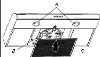
Illustration of a hand holding three circular components with a tool, no text or symbols presentWARRANTY
ELICA North America Two years limited warranty
TO OBTAIN SERVICE UNDER WARRANTY
Owner must present proof of original purchase date. Please keep a copy of your dated proof of purchase (sales slip) in order to obtain service under warranty.
PARTS AND SERVICE WARRANTY
For the period of two (2) years from the date of the original purchase, Elica will provide free of charge, non consumable parts or components that failed due to manufacturing defects. During these two (2) years limited warranty, Elica will also provide free of charge, all labor and in-home service to replace any defective parts.
WHAT IS NOT COVERED
Damage or failure to the product caused by accident or act of God, such as, flood, fire or earthquake.
Damage or failure caused by modification of the product or use of non-genuine parts.
Damage or failure to the product caused during delivery, handling or installation.
Damage or failure to the product caused by operator abuse.
Damage or failure to the product caused by dwelling fuse replacement or resetting of circuit breakers.
Damage or failure caused by use of product in a commercial application.
Service trips to dwelling to provide use or installation guidance.
Light bulbs, metal or carbon filters and any other consumable part.
Normal wear of finish.
Wear to finish due to operator abuse, improper maintenance, use of corrosive or abrasive cleaning products/pads and oven cleaner products.
WHO IS COVERED
This warranty is extended to the original purchaser for products purchased for ordinary residential use in North America (Including the United States, Guam, Puerto Rico, US Virgin Islands & Canada).
This warranty is non-transferable and applies only to the original purchaser and does not extend to subsequent owners of the product. This warranty is made expressly in lieu of all other warranties, expressed or implied, including, but not limited to any implied warranty of merchantability or fitness for a particular purpose and all other obligations on the part of Elica North America, provided, however, that if the disclaimer of implied warranties is ineffective under applicable law, the duration of any implied warranty arising by operation of law shall be limited to two (2) years from the date of original purchase at retail or such longer period as may be required by applicable law.
This warranty does not cover any special, incidental and/or consequential damages, nor loss of profits, suffered by the original purchaser, its customers and/or the users of the Products.
WHO TO CONTACT
To obtain Service under Warranty or for any Service Related Question
Please Call:
Elica North America Authorized Service at (888) 732-8018
Or by Writing To:
Elica North America, Attention Customer Service,
6658 156th Avenue SE,
Bellevue, WA 98006 USA
infoamericas@elica.com
natural_image
Simple line drawing of a rectangular object with two small circular holes on top (no text or symbols)MODELES EFS130
natural_image
Simple line drawing of a rectangular industrial chimney or duct (no text or symbols)MODELES ENM230 ENM236
APPROUVÉ POUR LES APPAREILS RÉSIDENTIELS POUR UTILISATION RÉSIDENTIELLE UNIQUEMENT. LIRE ET CONSERVER CES INSTRUCTIONS.
VEUILLEZ S.V.P. LIRE AVANT DE COMMENCER. INSTALLATION DOIT ÊTRE CONFORME AUX CODES LOCAUX.
PROPRIETAIRE: Please retain these instructions for future reference.
text_image
Technical diagram of a kitchen appliance with labeled dimensions A, B, C, D, E and internal componentstext_image
Technical diagram of a device casing with labeled components A, B, and C, showing internal layout and mounting points.NOTE: The 3¼" x 10" (8.3 x 25.4 cm) rectangular vent connector can be installed up to 1" (2.5 cm) on either side of the hood center to accommodate off center ductwork.
text_image
Labeled diagram of a mechanical or biological structure with points A, B, C, D, E, F marked.■ Rub in direction of grain to avoid scratching or damaging the surface.
■ For stainless steel models, use a special stainless steel cleaner and polish.
■ Liquid detergent or all-purpose cleaner: Rinse with clean water and dry with soft, lint-free cloth.
■ Glass cleaner to remove fingerprints.
natural_image
Illustration of a hand holding three circular components with a tool, no text or symbols presentGARANTÍE
Elica North America, Attention Customer Service,
6658 156th Avenue SE,
Bellevue, WA 98006 USA
infoamericas@elica.com
natural_image
Simple line drawing of a rectangular object with two circular indentations on top (no text or symbols)MODELOS EFN130
natural_image
Simple line drawing of a rectangular box with a curved top and a small circular mark on the side (no text or symbols)MODELOS ENM230 ENM236
DIMENSIONES DEL PRODUCTO
text_image
2" (5,1 cm) 6"½(16,7 cm) ó 9"½"(24,4 cm) 1" (2,5 cm) 4"½(12,5 cm) 1" (2,5 cm) 9" (22,9 cm) 29"½(76,0 cm) ó 35"½"(91,0 cm) 1½"(3,8 cm) 18"½"(47,3 cm)text_image
Technical diagram of a kitchen appliance with labeled dimensions A, B, C, D, and E for height measurement.text_image
Labeled diagram of a mechanical or anatomical structure with points A, B, C, D, E, F marked.B.Cables negros
text_image
Technical diagram showing a mechanical assembly with labeled parts A and B, likely illustrating a tool or component.natural_image
Line drawing of a hand holding a circular device with a handle, no text or symbols presentGARANTÍA
Elica North America, Attention Customer Service,
6658 156th Avenue SE,
Bellevue, WA 98006 USA
infoamericas@elica.com