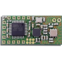
CX-12 R - Receiver SVS - Free user manual and instructions
Find the device manual for free CX-12 R SVS in PDF.


User questions about CX-12 R SVS
0 question about this device. Answer the ones you know or ask your own.
Ask a new question about this device
Download the instructions for your Receiver in PDF format for free! Find your manual CX-12 R - SVS and take your electronic device back in hand. On this page are published all the documents necessary for the use of your device. CX-12 R by SVS.
USER MANUAL CX-12 R SVS
text_image
control of supply voltage keep V always < VDD !! VDD = 2,0 .. 3,6 V DC SUPPLY VOLTAGE Voltage regulator 1 GND 0 VDD = 2,0 .. 3,6 V DC 0 V DC / GND Display analogue value received open = f1 closed = f2 Open = clocked operation closed = cw Learn/Erase CX-DR LED Ub-TX 270R Function LED 270R ANT1 ANTENNE use 17.3mm wire antenna or 5G Ohm coastal connection with ANT_GND OUT1 NPN OUT2 NPN OUT3 NPN OUT4 NPN potential free relux switch over contactsPlease read carefully!
These operating instructions form an integral part of this product and contain important information on how to commission, install and operate it. They must be taken into consideration and given to the end user or other third party when the installer hands over the product. These operating instructions must be retained for future reference.
Damage resulting from abuse or misuse is not covered by warranty. The manufacturer accepts no warranty for consequential losses that may result directly or indirectly from use of this equipment. Any changes or modifications not expressly approved by the party responsible for compliance could void the user's authority to operate the equipment. The product meets the requirements of the current European and national guidelines for electromagnetic compatibility. Conformity has been established and the relevant statements and documents have been deposited at the manufacturer.
1 Mode of operation
The receiver module CX-12 R detects serial data from the corresponding transmitter, and transmits back to the transmitter an acknowledgement with additional information. It is forbidden to modify or change component parts of the product. The electronic components are not protected against weather conditions. Therefore, it should not be used in the exterior without taking necessary precautions. The cable connections should not be longer than 1m. The CX-12 R is compatible with all transmitters of the 12 series including the transmitter module CX-12 T.

It should be noted that for applications that could put human life at risk, by using radio connection there is always present a potential hazard due to extraneous disturbances. The Operating Instructions need to be followed at all times.
2 Safety Precautions

- Every applicable regulations and standards have to be observed, in particular VDE0100, VDE0550/0551, VDE0700, VDE0711 and VDE0860. The use of solid cables for connection is recommended since terminal design does not incorporate stress relief. The product corresponds to Safety-Class II (without protective earth terminal) according to VDE0700, IEC335EN60335.
- For commercial use, compliance must be made with the recommendations and instructions of the responsible regional/national authorities.
- For use in public institutions, schools, clubs and do-it-yourself workshops the operation of this product has to be supervised by qualified personnel.
- We do not assume any warranty and liability for personal or material damages caused by incorrect application or by failure to follow these operating instructions.
- For reasons of safety and conformity (CE) it is not permitted to modify or change parts of the product.
• Installation of this product has to be performed by authorised electricians only. - If you have not the corresponding expertise, ask qualified specialists or workshop for installation and commissioning. This product and connected devices can be damaged as a result from inappropriate installation, connection or operation. Furthermore, this could lead to other damages e.g. short circuit, fire or electric shock.
- The product must not be installed or used in places where a risk of explosion may exist.
- Do not touch antenna connectors with live parts.
- The product should only be used in a case adequate for mains-voltage if applied!
• Electrical devices should be out of reach of children. Please be extra careful if children are around. - The module is a state-of-the-art product. However, there is a risk of danger if installation or operation is performed by unqualified personnel
3 System operating range
The system SH-12 is designed for a large operating range of many hundred meters. Walls including steel reinforced concrete can be penetrated. The maximum range can be achieved under optimum conditions and by line-of-sight contact between transmitter and receiver without disruption by external high frequency disturbances.
The following are possible causes that could reduce range of operation:
- Obstructing buildings, vegetation or other factors will substantially reduce the operating range.
- The distance between the antenna and the operator's body or other conducting objects (e.g. Earth) may influence the working range.
- Background “electrical noise” could be relatively high so that the signal-to-noise-ratio may decrease and therewith the operating range. Also other devices, with similar operating frequency, operated in the neighbourhood of the receiver may reduce the sensitivity.
- Operating the receiver adjacent to badly shielded electronic components (e.g. PC's) that can produce electromagnetic distortion, may severely reduce the range of operation and could result in intermittent operation.
- Adjustable and open components should not be adjusted or modified.
4 Description
CX12 R receives and demodulates the transmitter signal and forwards it to the 4 digital and 1 analog outputs. Transmitter signals are only accepted when the address matches with a previously learned one. Furthermore 2 outputs may control LED's to show to the user functionality and status of the transmitters battery. As long as valid data are received the corresponding outputs remain activated. Incoming OFF-signals deactivate immediately the assigned output. Due to distortions it may occur in rare cases that the receiver do not understand the OFF-signal. In this case outputs will be switched off after a delay of about 1.5 s.
CX-12 R may learn up to 60 different transmitter addresses. With the help of several different learn modes whole transmitters or single keys can be learned with or without acknowledgement.
In order to obtain a maximum of safety you may change over to a second working frequency if the first frequency channel is disturbed by another radio service.
After received data or power-on CX-12 R keeps continuous working for a period of 10 minutes. Then, in order to save energy, a clocked operation starts. That is why the next reception may be retarded up to 1s. If this delay is undesirable the clocked operation may be disabled.
text_image
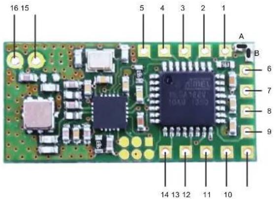
16 15 5 4 3 2 1 A B 6 7 8 9 14 13 12 11 10Pin description (see adjacent figure)
Pin 1 Input for selection of automatic clocked operation or continuous working Solder strap A connects pin 1 permanently to GND
Solder strap B open: +U or open: Clocked operation starts 10 minutes after power on or the last received data package GND: Receiver is set to continuous work Solder strap B closed: +U or open: Continuous clocked operation GND: Clocked operation starts 10 minutes after power on or the last received data package
Pin 2 Input to activate the Learn- or Erase mode
Initial state for selecting the learn- or erase mode is the normal receiving mode. The CX-12 R returns from learn- or erase mode to normal receiving mode if a valid signal has been received, or if pin 2 is connected to GND, or if the learn- and erase mode is already active more than 30s.

Transmitters learned in a specific learn mode will be configured in a specific way. Previous transmitter configurations will be overwritten.
Learn mode I – GND, 1x short (<1s): Learn transmitter – Communication with acknowledgement – The corresponding transmitter will be configured automatically Learn mode II – GND, 2x short (<1s): Learn single key – Communication with acknowledgement – The corresponding transmitter will be configured automatically Learn mode III – GND, 3x short (<1s): Learn transmitter – Communication without acknowledgement – The corresponding transmitter will be configured automatically. This feature is only compatible to transmitters from Version V xx.20. Learn mode IV – GND, 4x short (<1s): Learn single key – Communication without acknowledgement – The corresponding transmitter will be configured automatically. This feature is only compatible to transmitters from Version V xx.20. Erase mode I – GND, 1x long (>3s): Erase all list entries of the corresponding transmitter. Erase mode II – GND, 2x long (>3s): Erase the whole list of learned transmitters. The CX-12 R returns automatically to the normal receive mode.
Pin 3 Output to control a LED (low active)
Normal receive mode: Flashes for each data package received (twice for low U+ or U pin 12) Selection learn mode I: Light interrupts 1x every 2s Selection learn mode II: Light interrupts 2x every 2s Selection learn mode III: Light interrupts 3x every 2s Selection learn mode IV: Light interrupts 4x every 2s Selection erase mode I: Flashes permanently
Pin 4 Output D4
Digital output goes high with the ON information of the transmitter and switches to low immediately after reception of the OFF information. In case of missing OFF information while no more data are received the output remains at high level for another 1.5s (delay)
Pin 5 Output D3 same as output D4 (Pin4)
Pin 6 Analog value output
Output of the received analog value from the transmitter (value between +U and GND, Resolution 10bit, filtered PWM signal Ri=56 kOhm)
Pin 7 F2_SEL input to fix the working frequency
+U or open: Frequency 1 (433.62 MHz)
GND: Frequency 2 (434.22 MHz)
Pin 8 Output D2 same as output D4 (Pin4)
Pin 9 Output D1 same as output D4 (Pin4)
Pin 10 Positive voltage supply U+ between 2.0 and 3.6 V DC
Pin 11 Ground GND = 0V DC
Pin 12 Analogue input
The status of a supplied voltage is sent back to the transmitter and may be used for battery information on the receiver side. The 3 steps depends on the supply voltage. For +U = 3.3 V the steps are as follows:
Voltage > 1.2 V: Supply is ok – the transmitters LED remains off
Voltage 1,2 ... 1,1V: Supply low – the transmitters LED flashes slowly
Voltage 0,5 ... 1,1V: Supply empty – transmitters LED flashes quickly
Voltage < 0.5 V: Not allowed; for service purposes only
Pin 13 Output to control a piezo disc
Supply voltage protection: If the supply voltage drops below a critic level the CX-12 R shuts down and a specific melody sounds
Selection of learn- or erase mode: A specific melody sounds if a learn- or erase mode is selected
Leave learn- or erase mode: A specific melody sounds if a learn- or erase mode has been leaved
Learn or erase: A specific melody sounds if a transmitter or key has been learned or erased
Clear list: A specific melody sounds if the list of learned transmitters and keys has been cleared
Pin 14 Output to control a LED (low active)
Normal receive mode: Transmitter supply voltage low: Flashes 1x
Transmitter supply voltage empty: Flashes 2x
Learn- or erase mode: Entry could not be erased from list:
Flashes 2x
List is full – learning failed:
Flashes 3x
List already contains this transmitter or key:
Flashes 2x
Pin 15 Antenna GND e.g. connection for the shield of a 50Ohm-coaxial-cable
Pin 16 Antenna Connection e.g. for an antenna (173mm wire) or 50Ohm-coaxial cable.
5 Installation
For the location of the receiver module, select a place which is not shielded by conducting objects and position the antenna in such a way that it is not subject to interference from the rest of the circuit and is parallel to the transmitter antenna.

Pay attention to the correct polarity when performing the connections and make sure the technical data are kept within specifications. If the voltage supply exceeds the specified voltage, the electronic components may be destroyed, for example, when using unregulated voltage sources. Since the circuit is unprotected, it is necessary to avoid static discharges and mechanic influences.
Learning transmitters or keys:
Use pin 2 as described in point 4 to access the desired learn mode. You receive confirmation from pin 3. Now press one of the buttons of the transmitter in a distance of not less than 1m. You receive confirmation from pin 2 and pin 13. Check for error free operation the receivers output states by pressing the transmitter buttons.
Erase transmitter or keys:
Use pin 2 as described in point 4 to access the desired erase mode. You receive confirmation from pin 3. If the erase mode I is selected, press one of the buttons of the transmitter in a distance of not less than 1m. You receive confirmation from pin 2 and pin 13. Check for error free operation the receivers output states by pressing the transmitter buttons.
Wiring
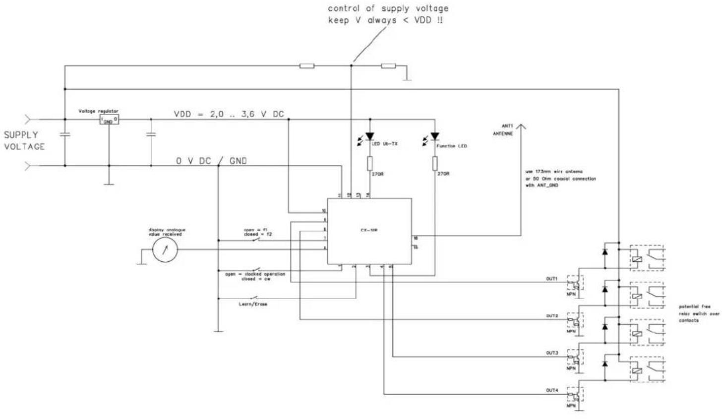
Please find enclosed a wiring example for the usage of different functions.
5 Technical Data
Working frequency: f1 433,62 MHz; f2 434,22 MHz
Max. transmission power: 10 mW
Antenna connection: 50 Ohm
Supply voltage: 2 - 3,6 V DC
Current consumption @ 3,3V: 18,2mA (clocked 1,4mA)
Current consumption @ 2,0V: 17,3mA (clocked 1,1mA)
Ambient temperature: -20^ to +65^
Dimensions: 31,4mm x 15,2mm x 3mm (pitch 2,54mm)
CIRCUIT EXAMPLE WITH CX-12 R
text_image
control of supply voltage keep V always < VDD !! SUPPLY VOLTAGE Voltage regulator VDD = 2,0 .. 3,6 V DC O V DC / GND display analogue value received open = f1 closed = f2 open = clocked operation closed = cw Learn/Erase CR-10R LED Ub-TX 270R Function LED 270R ANT1 ANTENNE use 17.5mm wire antennas or 50 Ohm coixial connection with ANT_GND OUT1 NPN OUT2 NPN OUT3 NPN OUT4 NPN potential free relax switch over contactstext_image
control of supply voltage keep V always < VDD !! SUPPLY VOLTAGE Voltage regulator I reg 0 VDD = 2,0 .. 3,6 V DC O V DC / GND dscivary amique value received open = f1 closed = f2 open + clocked operation closed = ce Learn/Eros CX-19R LED Ub-TX 270R 270R Function LED ANT1 ANTENNE use 173mm wire antenna or 53 Ohm coaxial connection with ANT_GND OUT1 NPN OUT/2 NPN OUT/3 NPN OUT/4 NPN potential free retry switch over contactstext_image
control of supply voltage keep V always < VDD !! VDD = 2,0 .. 3,6 V DC SUPPLY VOLTAGE Voltage regulator GND O V DC GND display analogue value received open = f1 closed = 12 open = clocked operation closed = ce CX-12R Lemn/Erase INT1 ANTENNE use 17.5mm wire antennas or 50 Ohm coaxial connection with ANT_GND DUT1 NPN DUT2 NPN DUT3 NPN DUT4 NPN potential free relay switch over contactoKonformitätserklärung trägt der Hersteller / This declaration of conformity is issued under the sole responsibility of the manufacturer:
2014/53/EU European Radio Equipment Directive (RED)
2011/65/EU Restriction of Hazardous Substances (RoHS)
Quality Management System
www.lw.soc.domino-zerl