
X10 Bad Buster 2.0 - Remote control toy Carson - Free user manual and instructions
Find the device manual for free X10 Bad Buster 2.0 Carson in PDF.

| Product Type | Remote controlled toy, electric buggy model |
| Brand | Carson |
| Model | X10 Bad Buster 2.0 |
| Scale | 1/10 (estimated) |
| Vehicle Power | Rechargeable lithium battery (not included, specifications in manual) |
| Transmitter Power | Batteries (type and number not specified) |
| Motor | Electric, brushless type (estimated) |
| Transmission | 4-wheel drive (estimated) |
| Maximum Speed | Varies based on battery, approx. 30-50 km/h (estimated) |
| Runtime | Approx. 10-20 minutes depending on usage and battery |
| Remote Control Range | Up to 100 meters (estimated) |
| Main Functions | Forward/reverse, left/right steering, braking |
| Maintenance and Cleaning | Clean after use with a dry cloth, do not immerse, check screws and nuts regularly |
| Safety | Do not use on public roads, under high-voltage lines, or in bad weather. Suitable for children over 14 years under adult supervision. |
| Spare Parts and Repairability | Use only original Carson spare parts. Repairs by an approved body to preserve warranty. |
| Warranty | 24 months from date of purchase from an authorized dealer, covers manufacturing and material defects |
| General Information | Manual available in several languages. CE compliance declaration available online. |
Frequently Asked Questions - X10 Bad Buster 2.0 Carson
User questions about X10 Bad Buster 2.0 Carson
0 question about this device. Answer the ones you know or ask your own.
Ask a new question about this device
Download the instructions for your Remote control toy in PDF format for free! Find your manual X10 Bad Buster 2.0 - Carson and take your electronic device back in hand. On this page are published all the documents necessary for the use of your device. X10 Bad Buster 2.0 by Carson.
USER MANUAL X10 Bad Buster 2.0 Carson
Before using your product for the first time or ordering any spare parts, check that your manual is fully up-to-date. This manual contains the technical appendices, important instructions for correct start-up and use and product information, all fully up-to-
date before going to press. The contents of this manual and the technical data of the product can change without prior notice.
For the latest version of your manual, see: www.carson-modelsport.com
FR // Remarque importante
natural_image
Line drawing of a toy car with a hand holding a pen, no text or symbols present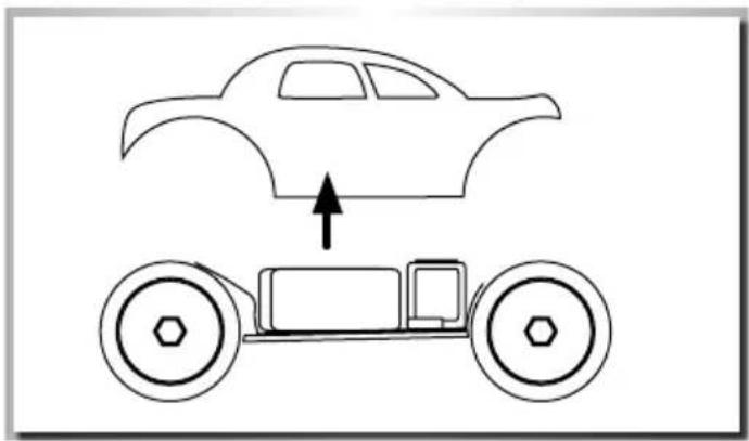
natural_image
Simple line drawing of a car above a toy car with an upward arrow indicating motion (no text or symbols)AUFLADEN DES FAHRAKKUS
LiPo 7.4 V 1700 mAh


EINLEGEN DER FAHRAKKUS
natural_image
Line drawing of a hand operating a mechanical device with no visible text or symbolsBINDING
natural_image
Diagram of a car front view showing two tires and a steering wheel (no text or symbols)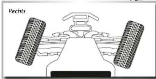
natural_image
Diagram of a vehicle's front view showing two tires and a central body, labeled 'Rechts' (no other text or symbols)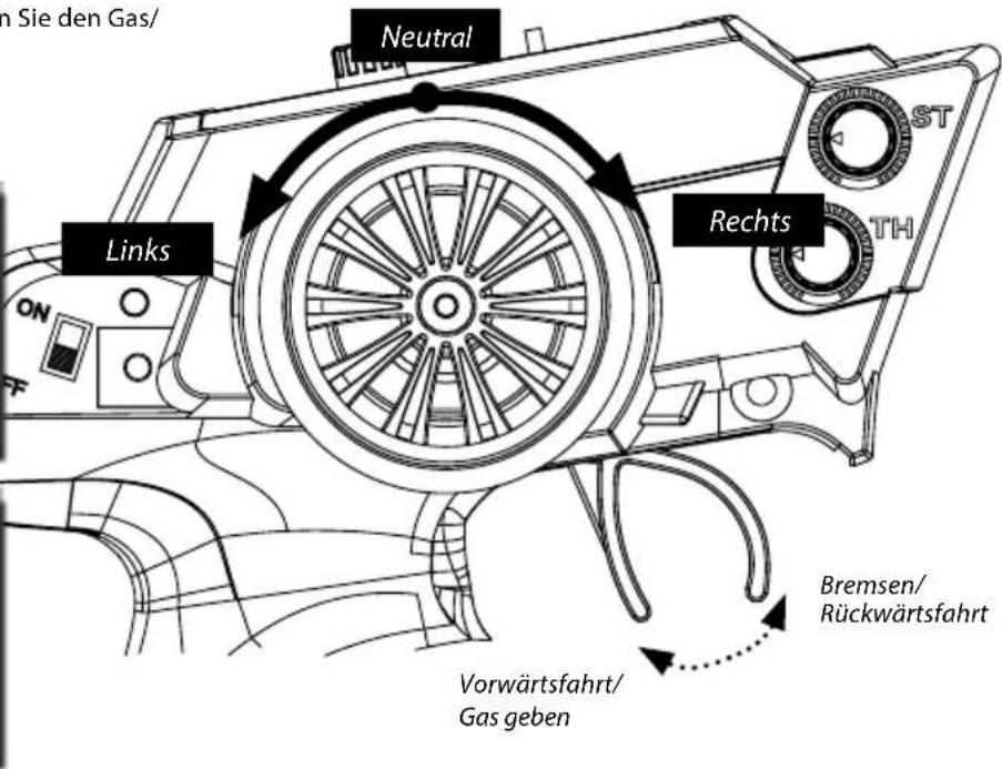
We congratulate you for buying this CARSON product, which is designed and manufactured using state of the art technology.
According to our policy of continued development and product improvement we reserve the right to make changes in specifications regarding equipment, material and design at any time without notice.
Specifications or designs of the actual product may vary from those shown in this manual or on the box.
The manual forms part of this product. Should you ignore the operating and safety instructions, the warranty will be void.
Keep this guide for future reference.
Limited Warranty
This product is warranted by CARSON against manufacturing defects in materials and workmanship under normal use for 24 months from the date of purchase from authorised franchisees and dealers. In the event of a product defect during the warranty period, return the product along with your receipt as proof of purchase to any CARSON store.
CARSON will, at its option, unless otherwise provided by law:
(a) Correct the defect by repairing the product without charging for parts and labour;
(b) Replace the product with one of the same or similar design.
All replacement parts and products, and products on which a refund is made, become the property of CARSON. New or reconditioned parts and products may be used in the performance of warranty services.
Repaired or replaced parts and products are warranted for the remainder of the original warranty period. You will be charged for repair or replacement of the product made after the expiration of the warranty period.
The Warranty does not cover:
- Damage or failure caused by or attributable to acts of God, abuse, accident, misuse, improper or abnormal usage, failure to follow instructions, improper installation or maintenance, alteration, lightning or other incidence of excess voltage or current;
- Damage caused by losing control of your model;
- Any repairs other than those provided by a CARSON authorised service facility;
- Consumables such as fuses or batteries;
- Cosmetic damage;
- Transportation, shipping or insurance costs; or
- Costs of product removal, installation, set-up service adjustment or reinstallation;
- Any changes to plugs and cables, open the housing and damage the sticker.
This warranty gives you specific legal rights, and you may also have other rights which may vary according to the country of purchase.
Declaration of conformity
TAMIYA-CARSON Modellbau GmbH & Co. KG hereby declares that the radio equipment type 500402129 conforms to Directive 2014/53/EU. The complete text for the EU declaration of conformity is available at the following Internet address.
The explanation of the symbol on the product, packaging or instructions: Electronic devices are valuable products and should not be disposed of with the household waste when they reach the end of their service life! Help us to protect the environment and respect our resources by delivering this appliance to the relevant recycling point.

We wish you a lots of fun using your CARSON product!
Before use, read this manual carefully!
CONTENTS
Preface ....11
Scope of delivery....12
Technical data....12
Safety Precautions....13
Safety Precautions lithium batteries.... 14
Chassis....15
Removing the Body....15
Charge battery pack....16
Inserting the drive batteries 16
Your Transmitter 16
Installing the transmitter batteries....17
Turn on the RC System....17
Binding 17
How to Control Your Model.... 18
Troubleshooting....19
Assembly instructions 31
Spare Parts 51
SCOPE OF DELIVERY
-
RC model
-
Remote Control
-
Li-Ion battery 7.4 V
-
1.5V AA (LR06) transmitter batteries
-
Plug-in charger
-
Manual
TECHNICAL DATA
- Model with 2.4 GHz RC system (max. transmitter power 10 mW)
• Transmitter operating voltage: 4.8-6 V
• Vehicle operating voltage: 7.4 V
- Function:
- Move forwards/backwards/brake
- Steering left/right
- Dual rate function: ride/steering
SAFETY PRECAUTIONS
Safety Instructions and Intended Use
This product is designed exclusively for hobby use and may only be used on tracks and areas intended for this purpose.
No persons or animals may be transported with this model.
To avoid operator errors, it is mandatory that the user manual is read before use!
These models may only be used with bodywork that is correctly fitted.
When removing the bodywork, please note that, during operation, certain parts can become very hot.
Please note that various models can generate very high noise levels and should, therefore, not be operated in your immediate proximity.
Please make sure, before every driving session, that the tank is correctly closed or the power pack is correctly inserted.
To avoid faulty operation of the control system causing the model to run out of control, it must be checked that the transmitter and model batteries are in good condition.
It is essential to check that the model is correctly assembled both before and after use; if need be, tighten nuts and bolts.
This model is not a toy!
- This product is not a toy, its operation must be learned step by step.
- Children under 14 years of age should operate the model only if supervised by an adult.
Operating RC models is a fascinating hobby that, however, must only be exercised with proper precautions and care. Since the weight of this model is considerable and it can reach a very high speed it can, if it runs out of control, cause significant damage and injury for which you, as the operator, are liable.
Only a correctly assembled model will work and react as expected. Never improvise with unsuitable materials but, when the need arises, use only original spare parts. Even if the model is pre-assembled, all joints and fastenings should be checked for correct seating and tightness.
Before use, you must make sure of the following points:
- All rechargeable batteries must be fully charged.
• Before starting, check the radio range. - Check that the model reacts correctly to the control signals.
- All functional parts of the product are in a faultless condition and have been checked.
- All screw fastenings are firmly seated.
- Do not drive under high-voltage power lines or radio masts or with nearby thunderstorms!
- Atmospheric interference can influence the operation of your model.
- The electrical parts of the model are not water-tight. Do not, therefore, drive it in rain or snow or through puddles or wet grass.
- The remote controlled model may be driven only on suitable areas and must not be used on the public highway.
- Do not use near people or animals!
- Do not use it when tired or if your reactions are otherwise impaired.
• Always maintain direct visual contact with your model. - Regular maintenance and care are required for first class driving performance.
- The model has parts that become hot in operation, e.g. the top of the motor, the metal gearbox, amongst many others. Touching these parts during operation can cause injury.
Pay attention to the charge level indication on your transmitter.
- With power packs or batteries that are half discharged, you can lose control of the model.
- In the transmitter, never mix fully charged batteries, rechargeable or not, with half discharged batteries or rechargeable batteries of different capacity.
- Never try to charge non-rechargeable batteries (dry cells), only batteries specified as rechargeable can be charged.
SAFETY PRECAUTIONS LITHIUM BATTERIES
1. General
Lithium batteries (accumulators) are energy storage devices with a high energy density and can present risks. For this reason, particular care is needed when charging, discharging, storing and handling.
Read these instructions very carefully before first using the battery. Do not fail to take note of the warning notices and instructions for use.
Misuse can lead to risks such as explosion, overheating or fire.
Failure to observe the instructions for use leads to early failure and other defects.
The instructions should therefore be kept in a safe place and it is essential that they are handed over to the second user if the batteries are passed on.
2. Warning notices
- Avoid short-circuits. A short-circuit may well destroy the product. Cables and connections must be well insulated.
- It is essential when connecting the battery to ensure that the polarity is correct.
- Original plug connectors and cables may not be cut off or changed - if need be, use an adapter cable.
- Do not expose the battery to excessive heat or cold or to direct sunlight. Do not throw in the fire. Do not place the battery in contact with water or other liquids.
- Charge the battery only with charging units intended for the purpose and always use the balancer connection. It is only by using the balancer connection that optimum charging can be ensured. If this connection is not used, charging is subject to the risks mentioned above. Before charging, always first allow the battery to cool to ambient temperature. Never charge while hot.
- When charging, place the battery on a non-flammable, heat-resistant support. There should be no flammable or readily ignited objects in the vicinity of the battery.
- During charging or operation, never leave the battery unsupervised.
- Do not fail to keep to the recommended charge/discharge current.
- The battery casing must not be damaged. It is essential to avoid damage by sharp objects such as knives or the like, from dropping, impact, bending etc. Damaged batteries may no longer be used.
- Batteries are not toys. They should be kept away from children.
3. Charging instructions
Lithium batteries are charged according to the CC-CV procedure. CC stands for "constant current", which is applied during the first phase of charging. Once the battery reaches the maximum voltage configured in the charger, it switches to CV (constant voltage) for the second phase of charging. The battery voltage no longer increases. The charging current now falls continuously until the battery is fully charged. The maximum charging current for the battery is 1C (C=nominal capacity of the battery, e.g. for a battery with a nominal capacity of 2700 mA, the maximum charging current for the battery is 2700 mA (2.7 A)). Never charge several batteries together from a single charger. Differing states of charge and capacities can lead to overcharging and destruction.
4. Storage instructions
Lithium batteries should be stored charged to 20-50 % of their capacity and at a temperature of 15-18 °C. If the cell voltage falls below 3 V, they should be recharged. Deep discharge and storage when discharged (call voltage <3 V) will render the battery unusable.
5. General terms of guarantee
There is a legal guarantee for production and material faults as applicable at the time of dispatch. No liability is accepted for normal wear and tear. This guarantee does not apply for defects attributable to improper use, inadequate maintenance, third-party interference or mechanical damage. This applies, in particular, to used batteries and batteries clearly showing signs of use.
Damage and loss of performance due to improper handling and/or overload are not product faults. Batteries are consumables and subject to a certain ageing. This is influenced by factors such as the charge/discharge currents, the charging procedure, the operating and storage temperatures and the state of charge during storage. The ageing shows itself in, among other things, an irreversible loss of capacity. In the model field, where batteries are frequently used to supply motors, very high currents can flow from time to time.
6. Exclusion of liability
Since we are unable to have any control over charge/discharge, handling, compliance with assembly and operating instructions, battery replacement and its care and maintenance, Tamiya / Carson can accept no liability for loss, damage or costs incurred.
Any claim for damages that may result from operation, failure or faulty operation or that is in any way related thereto will therefore be refused. We accept no liability for personal injury or material damage and their consequences that arise from our delivery.
7.Disposal instructions
Batteries are hazardous waste. Damaged or unusable cells must be disposed of in the correct manner.
No liability for printing errors, we reserve the right to make changes!
CHASSIS

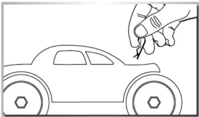
REMOVING THE BODY
- Remove hook pin (4) and • Take body off.
natural_image
Line drawing of a toy car with a hand holding a tool near it (no text or symbols)
natural_image
Simple line drawing of a car above a toy car with an upward arrow indicating motion (no text or symbols)CHARGE BATTERY PACK

LiPo 7.4 V 1700 mAh


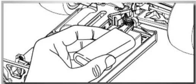
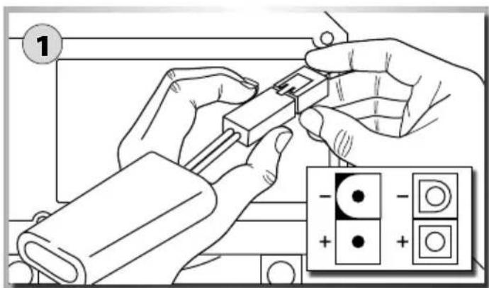
INSERTING THE DRIVE BATTERIES
1 Insert the batteries
2 Put the battery plate on it and
3 Fix it with the screw-nuts
Advice
• Non-rechargeable batteries are not to be recharged.
- Rechargeable batteries are to be removed from the toy before being charged.
- Rechargeable batteries are only to be charged under adult supervision.
- Batteries are to be inserted with the correct polarity.
- Exhausted batteries are to be removed from the toy.
natural_image
Line drawing of a hand holding a mechanical component, no text or symbols present- The supply terminals are not to be short-circuited.
- Regular examination of transformer or battery charger for any damage to their cord, plug, enclosure and other parts.
YOUR TRANSMITTER
Transmitter overview
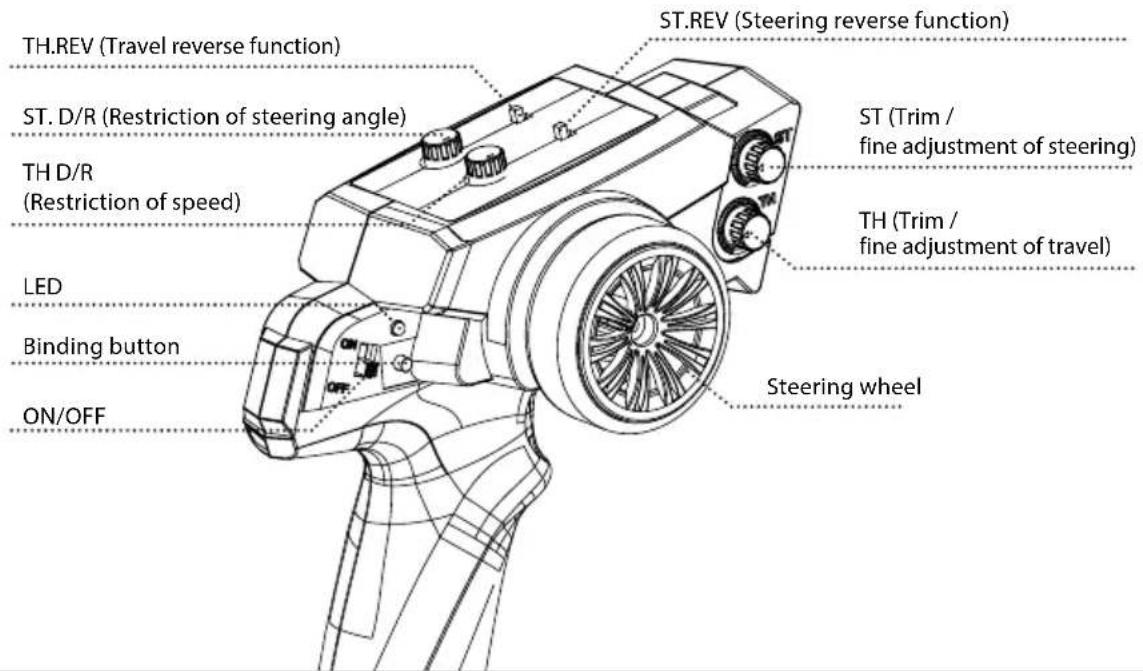
INSTALLING THE TRANSMITTER BATTERIES
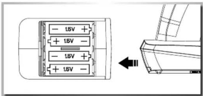
- Open the battery compartment lid on the underside of the transmitter.
- Insert fully charged rechargeable batteries or new AA batteries observing the correct polarity. Close the cover on the battery compartment again. Ensure that the cover clicks properly into place. Check that it is in its correct position.
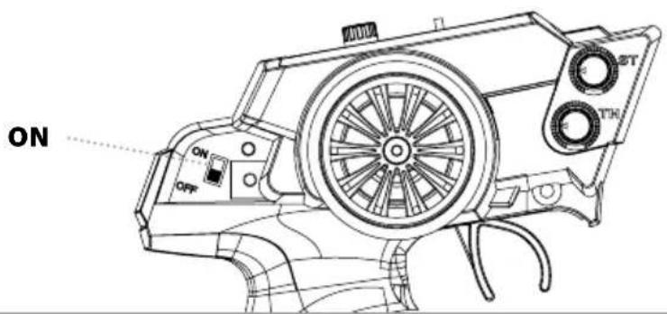
TURN ON THE RC SYSTEM
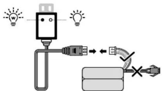
CAUTION!
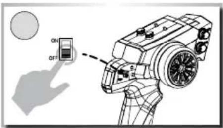
Always turn the transmit - ter's power switch ON first!
Please change batteries when LED status flashes on transmitter!!!
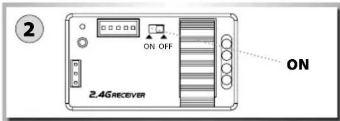
1 Connect the rechargeable battery for the driving.
2 Switch on the receiver.
3 Put the body on and fix it with the body split pins.
BINDING
Connecting transmitter and receiver:
The vehicle is ready to drive when it leaves the factory. In normal circumstances, therefore, the binding function is not necessary!
The binding function should only be used if there are any connection problems between the vehicle and the transmitter or if the transmitter/receiver is replaced.
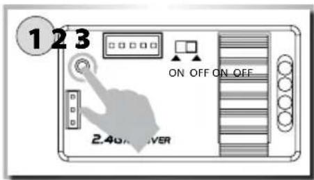
Press and hold down the Binding button on the receiver and then switch on the receiver. The LED on the receiver then flashes rapidly!
Press and hold down the Binding button on the transmitter and then switch on the transmitter.
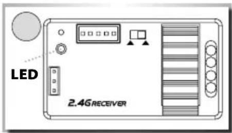
The binding process is completed when the LED on the receiver is permanently illuminated.
HOW TO CONTROL YOUR MODEL
- Raise the tyres off the ground
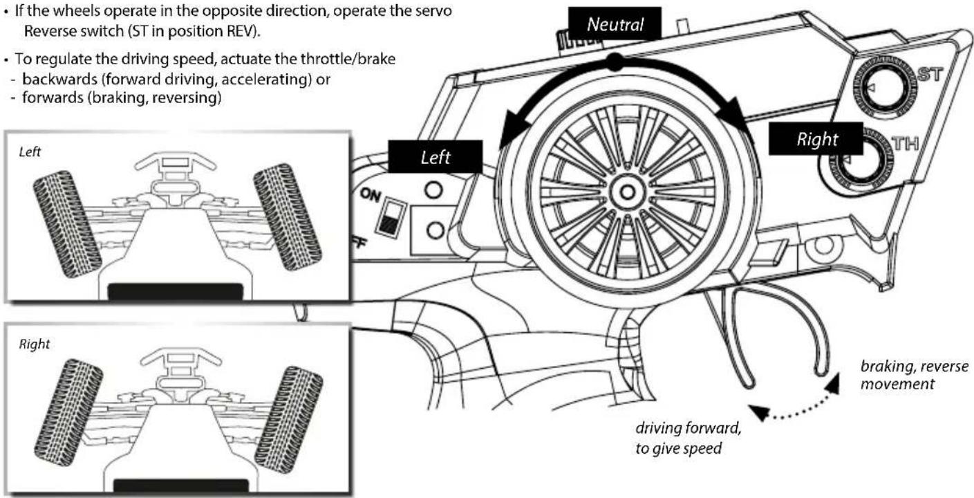
- Turn the steering wheel to the right and left as far as it will go. The wheels are to follow the steering direction.
- If the wheels operate in the opposite direction, operate the servo Reverse switch (ST in position REV).
- To regulate the driving speed, actuate the throttle/brake
- backwards (forward driving, accelerating) or
- forwards (braking, reversing)
TROUBLESHOOTING
| Problem Cause Correction | ||
| Model doesn’t move Transmitter or chassis power switch is not "ON" | Switch power on receiver or transmitter | |
| Polarity or battery type is wrong Check polarity and type of battery | ||
| Batteries have run down Change batteries or charge them | ||
| Loss of control | Batteries have run down | Change batteries or charge them |
| Antenna is missing or not attached properly Attach receiver antenna | ||
| Doesn’t run straight | Steering trim is not adjusted correctly | Make adjustment |
| Front and rear wheel nuts are too lose Tighten wheel nuts | ||
| Doesn’t stop | Throttle trim is not adjusted correctly | Make adjustment |
| Doesn’t reverse | Throttle trim is not adjusted correctly | Make adjustment |
| Wrong action | Control properly | |
| Running too slowly | Batteries have run down | Change batteries or charge them |
| Motor has lost power | Change to spare motor | |
| Rear wheel nuts are too lose | Tighten wheel nuts | |
| Dust or foreign objects are inside gears | Turn the power switch "OFF" and clean out gears | |
Cher client
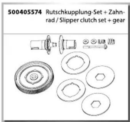
Here is the manual for the slipper-clutch device that offers both traction control and protection for the transmission. The slipper is primarily used to help absorb sudden impacts on the drivetrain due to landing big jumps or driving in hard terrain. Additionally, it can be used to smooth out the flow of power to the wheels and limit wheel spin when running on extremely slick surfaces.
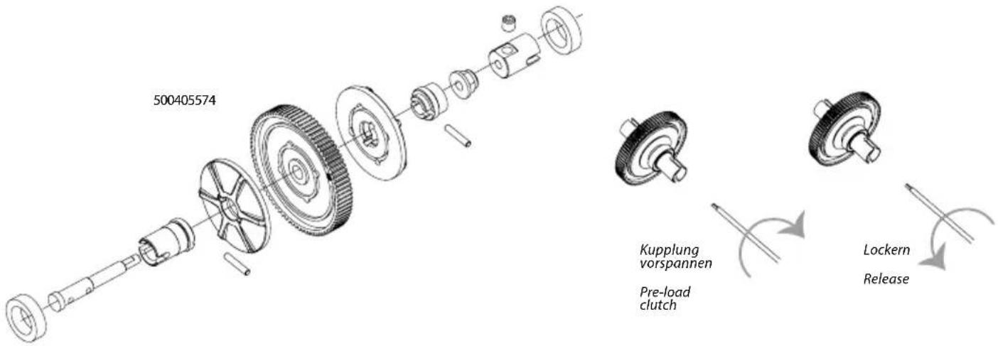
Slipper-clutch adjustments
Adjustments are made adjusting the slipper nut clockwise (to the right) to reduce the slip or counterclockwise (to the left) to increase the slip.
When adjusted properly, you should be able to hold the tires firmly and barely be able to push the spur gear forward with your thumb. To track test, switch the modelcar on and place it on the ground. As you push it backwards, allowing it to roll freely, punch the throttle. The slipper should slip no more than an inch or two as it accelerates.
natural_image
Technical line drawing of a mechanical component with gears and housing (no text or symbols)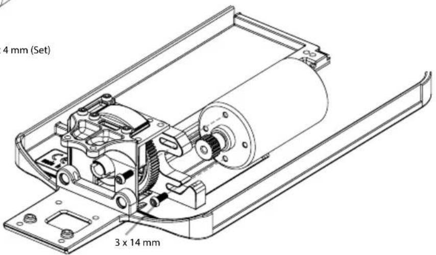
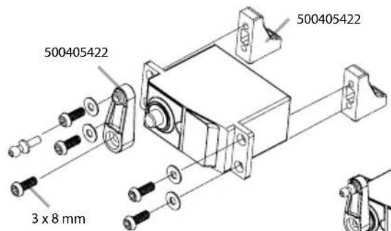
5. MONTAGE SERVO • SERVO ASSEMBLY
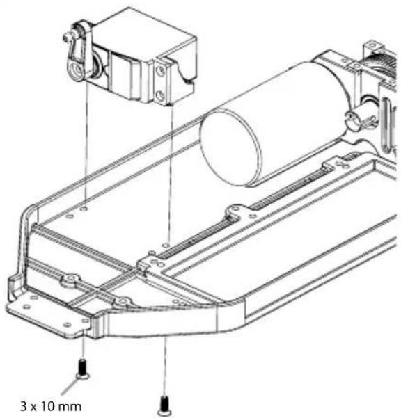
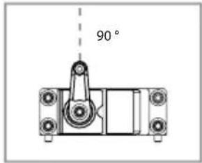
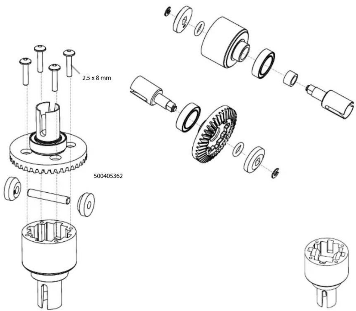
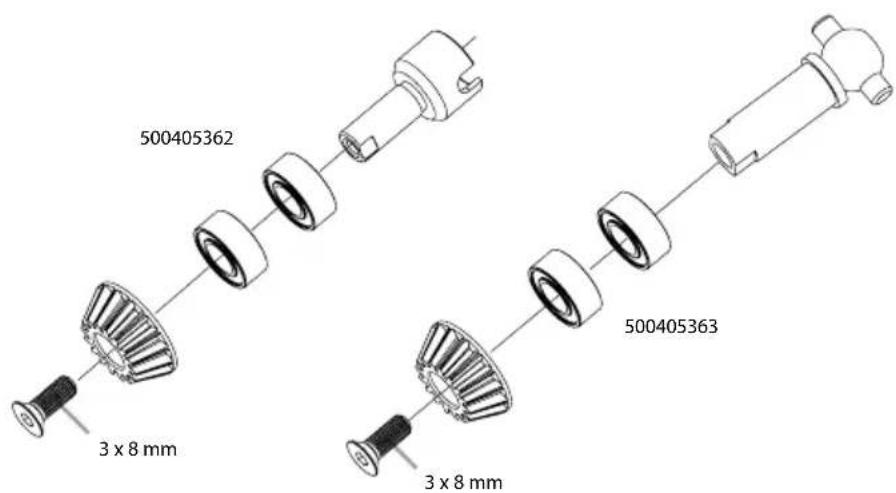
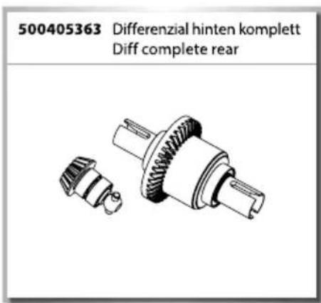
6. MONTAGE DIFFERENZIAL • DIFF ASSEMBLY
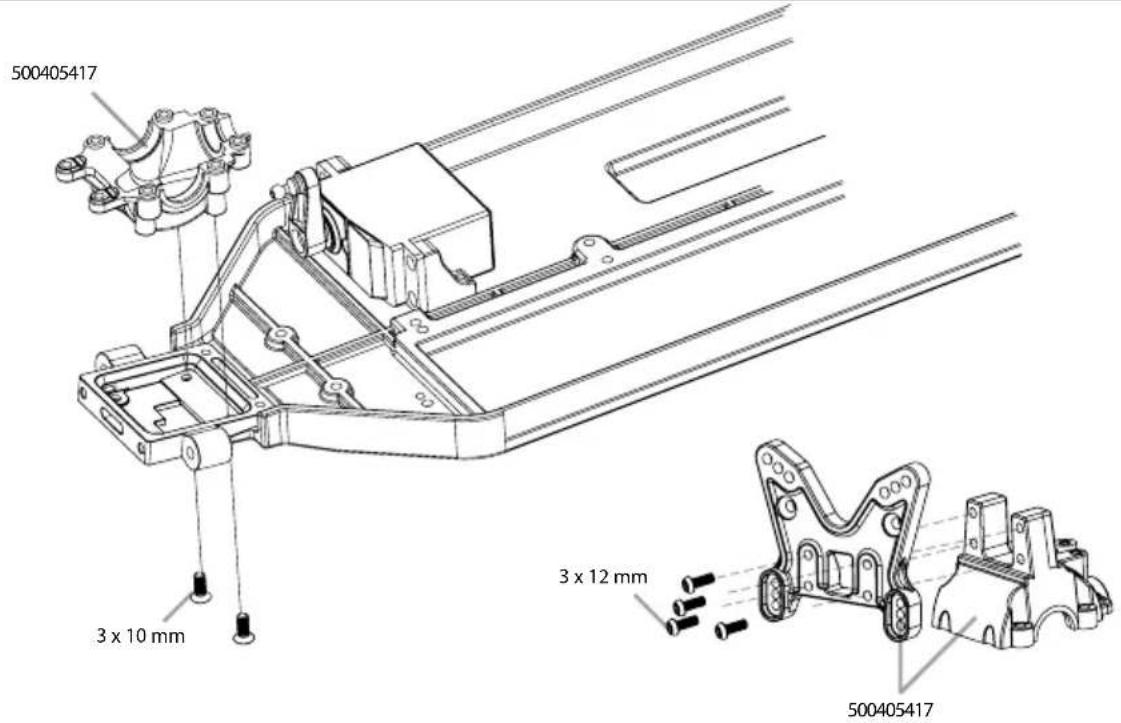
- DÄMPFERBRÜCKE HINTEN • REAR SUSPENSION MOUNT
- MONTAGE ANTRIEB • DRIVE ASSEMBLY
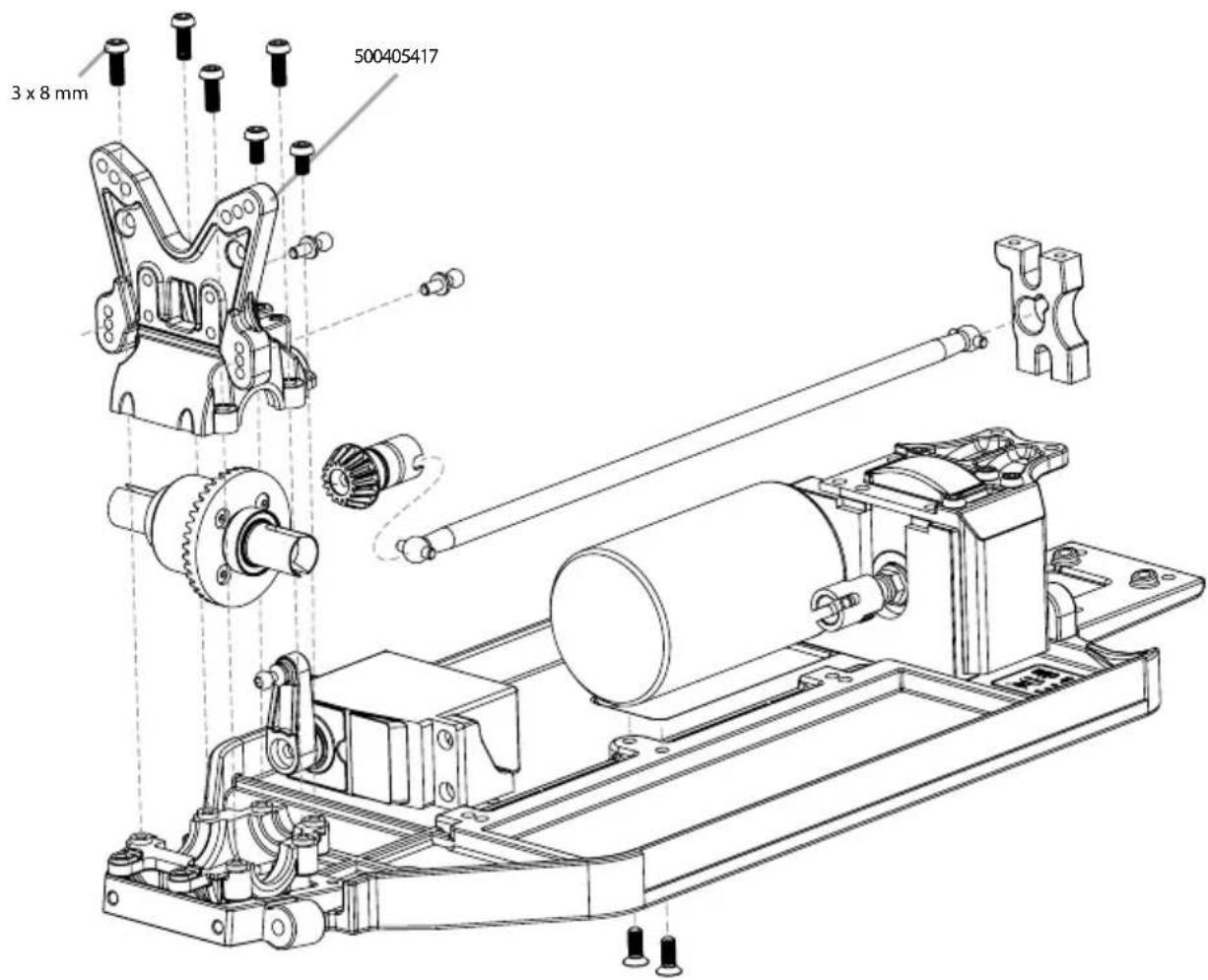
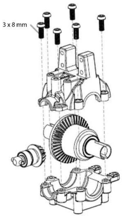
9. GETRIEBEBOX • GEAR HOUSING
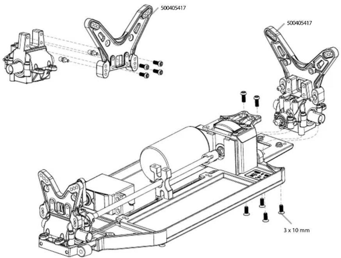
10. DÄMPFERBRÜCKEN • SUSPENSION MOUNTS
11. MONTAGE LENKUNG • STEERING ASSEMBLY
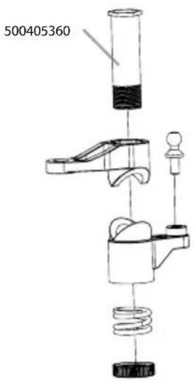
natural_image
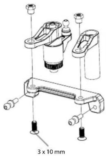
Technical line drawing of a mechanical assembly with gears and shafts, no visible text or symbols12. MONTAGE LENKUNG • STEERING ASSEMBLY
13. MONTAGE ANTRIEB VORNE • FRONT DRIVE ASSEMBLY
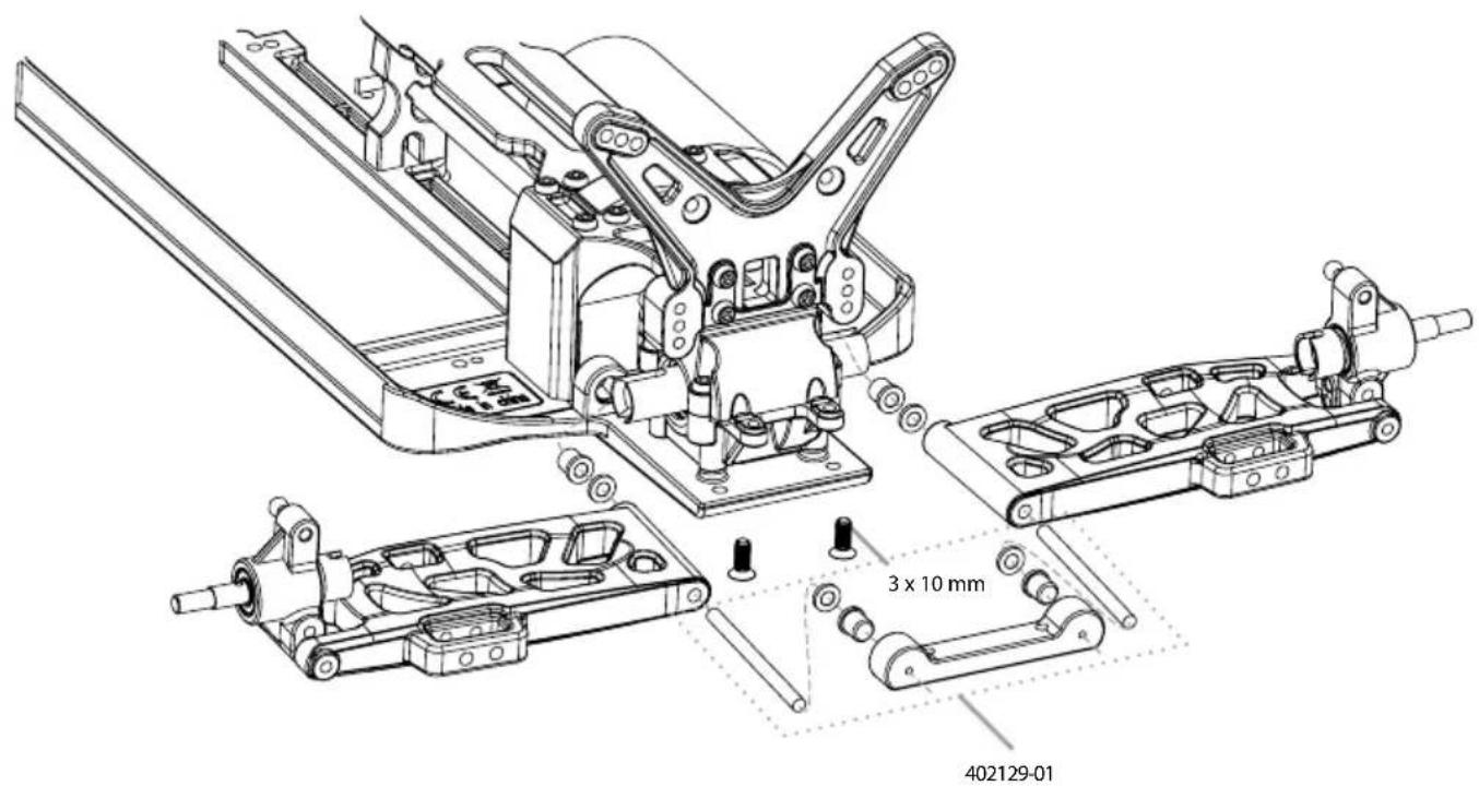
14. MONTAGE QUERLENKER • SUSPENSION ARMS ASSEMBLY
natural_image
Technical line drawing of mechanical assembly with no visible text or symbols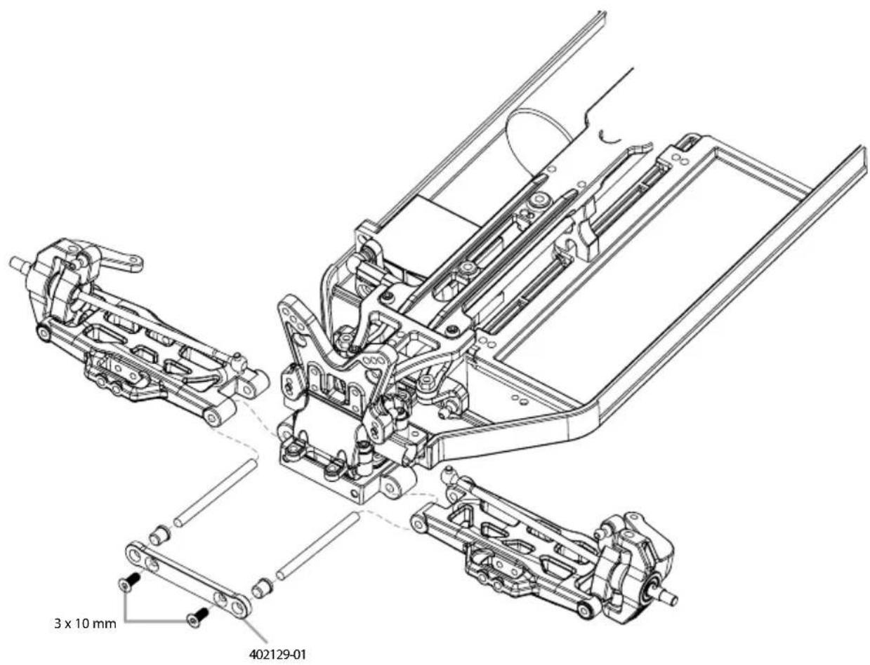
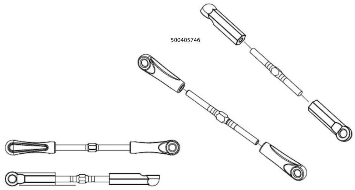
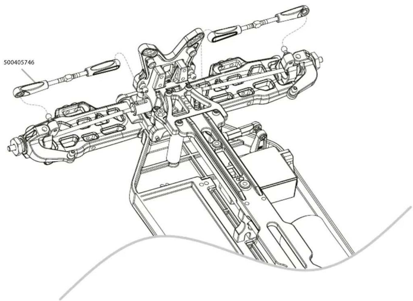
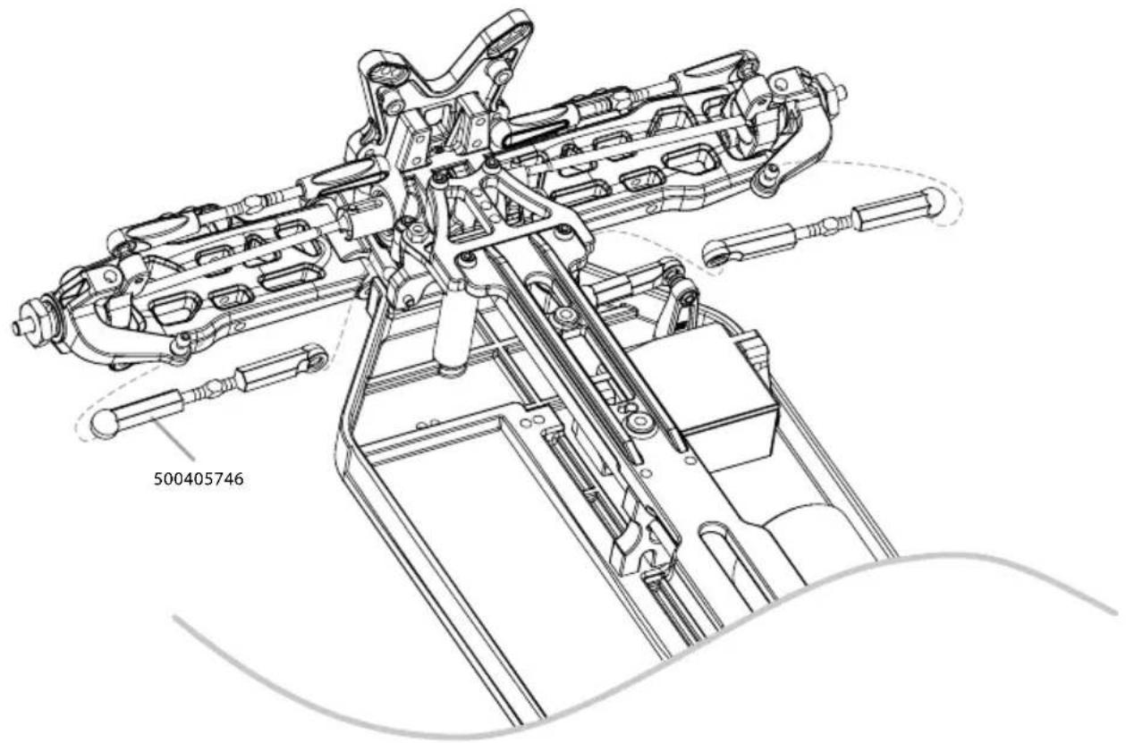
- MONTAGE GESTÄNGE • TURNBUCKLE ASSEMBLY
16. MONTAGE LENKUNG • STEERING ASSEMBLY
- QUERLENKER HINTEN • REAR SUSPENSION ARMS
- MONTAGE ANTRIEBSKNOCHEN • DOGBONES ASSEMBLY
natural_image
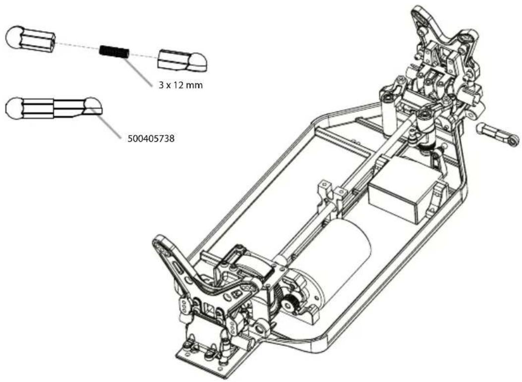
Technical line drawing of a mechanical linkage component with two views (top and side), no text or symbols present.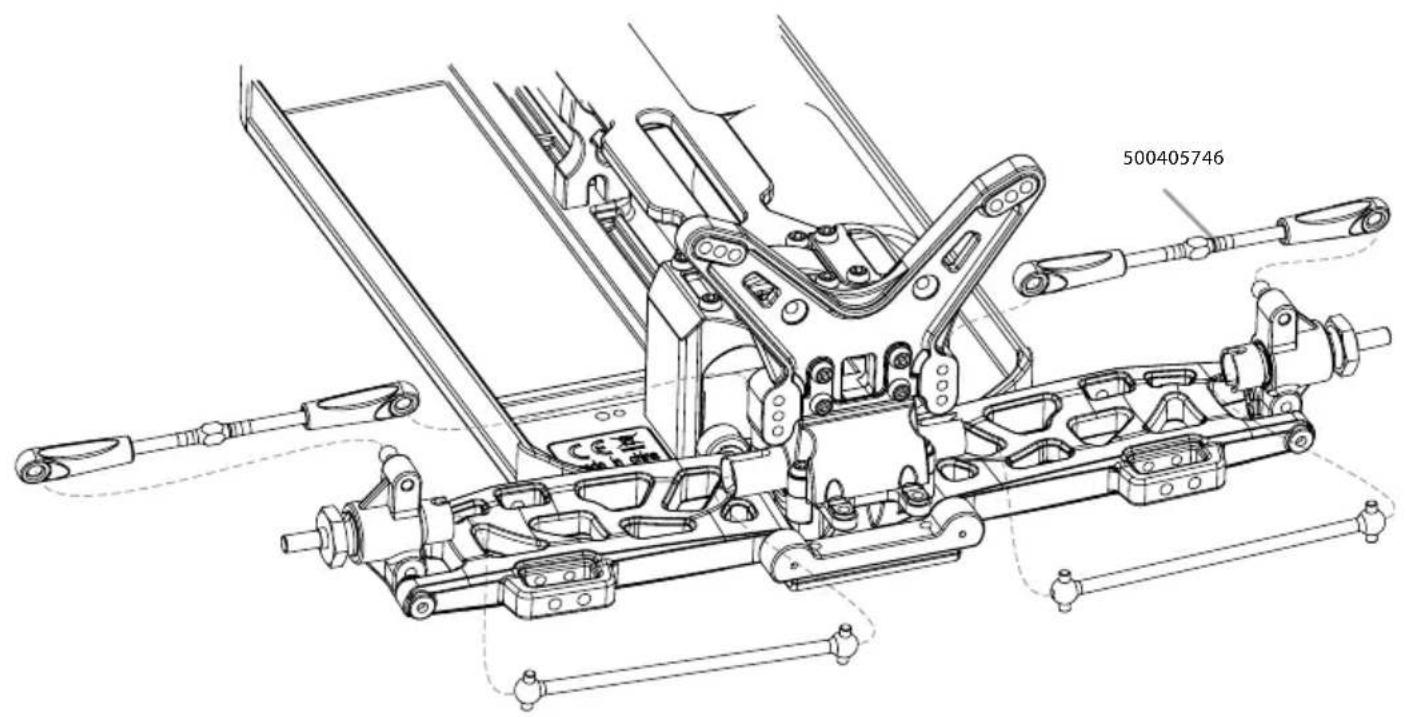
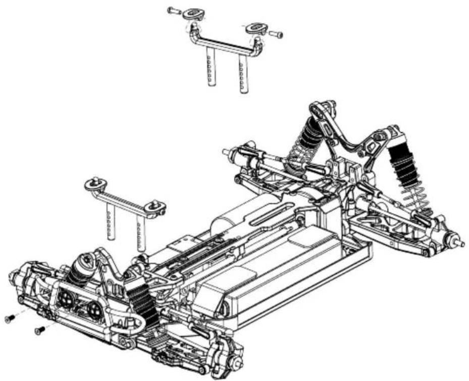
19. MONTAGE STABILISATOREN • SWAY BAR ASSEMBLY
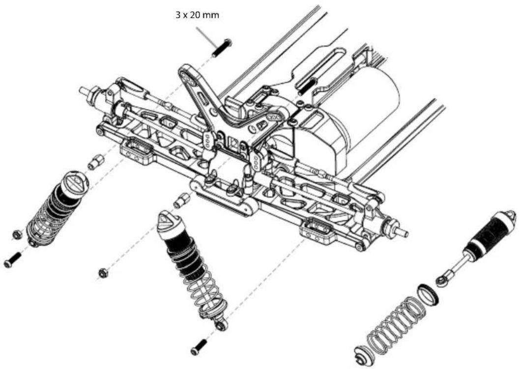
- MONTAGE STOSSDÄMPFER • SHOCK SET ASSEMBLY
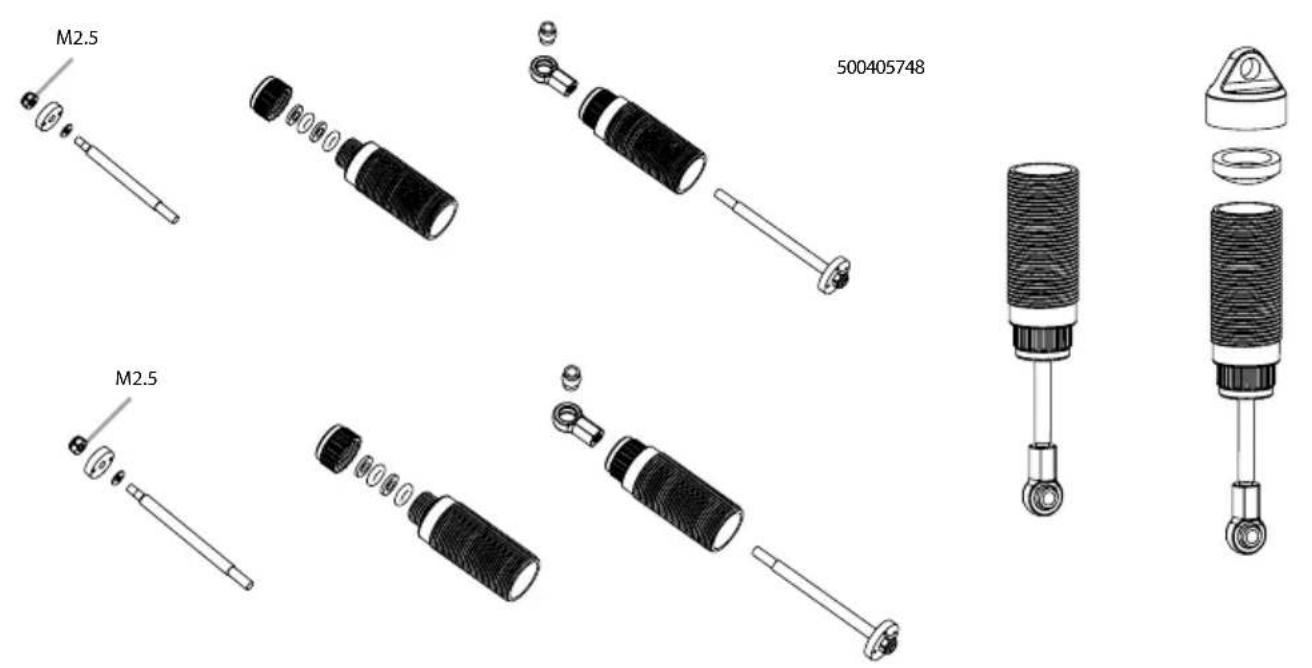
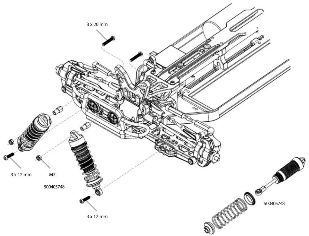
21. MONTAGE STOSSDÄMPFER • SHOCK SET ASSEMBLY
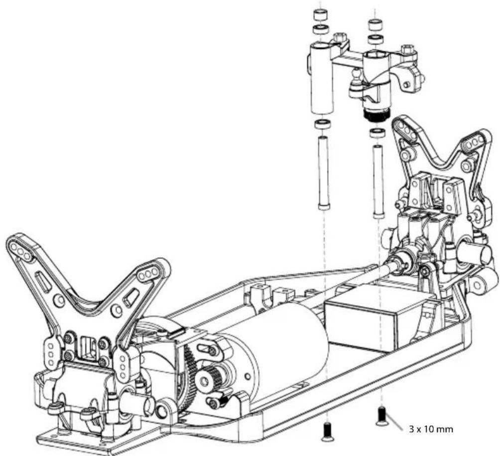
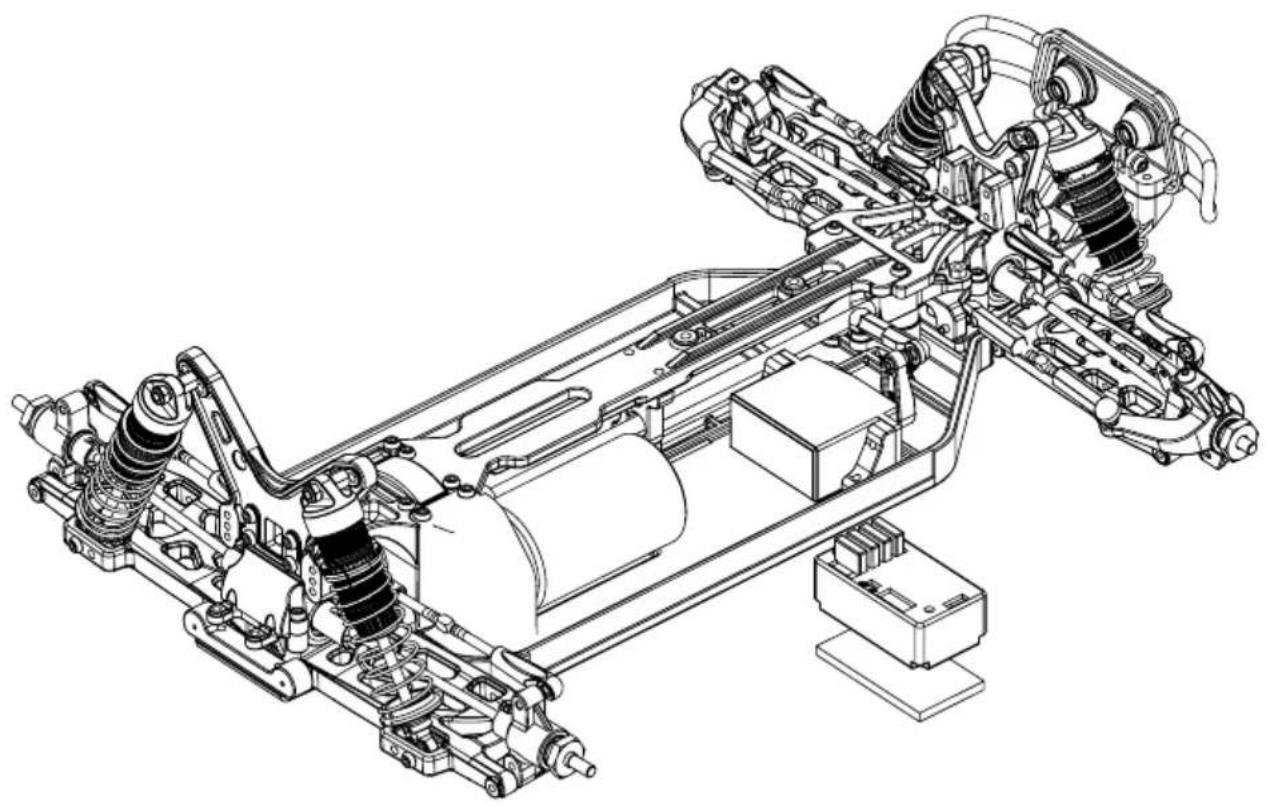
22. MONTAGE RC-SYSTEM • ASSEMBLY RC SYSTEM
natural_image
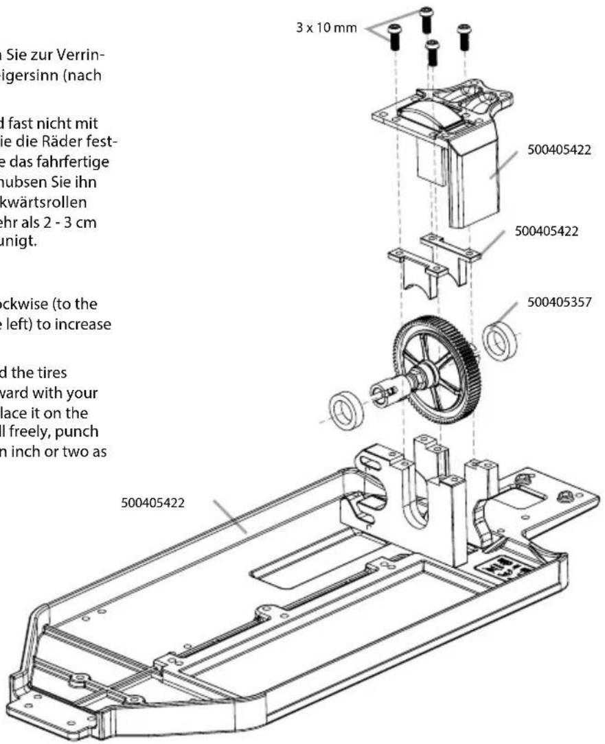
Technical line drawing of a vehicle chassis with suspension systems and suspension components (no text or labels)23. MONTAGE AKKUHALTER • BATTERY HOLDER ASSEMBLY
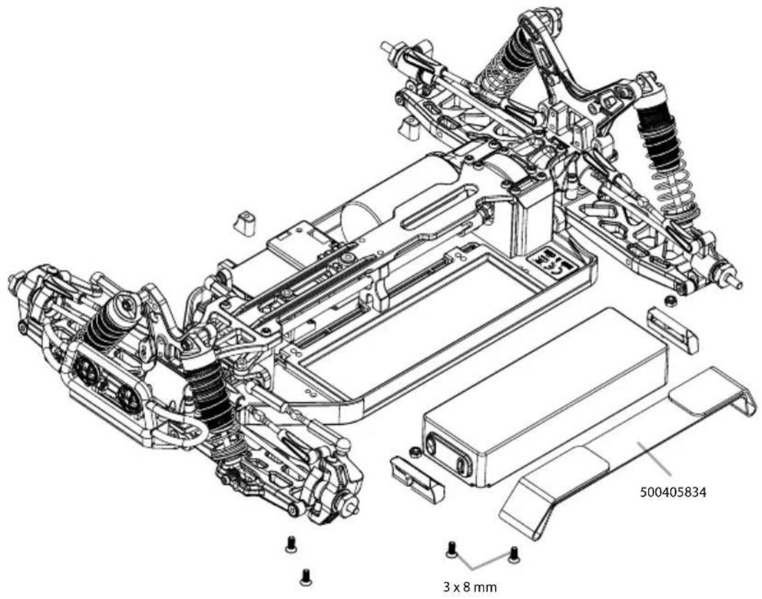
24. MONTAGE LICHT • LIGHT ASSEMBLY
natural_image
Technical line drawing of a vehicle chassis with suspension components and mounting brackets (no text or symbols)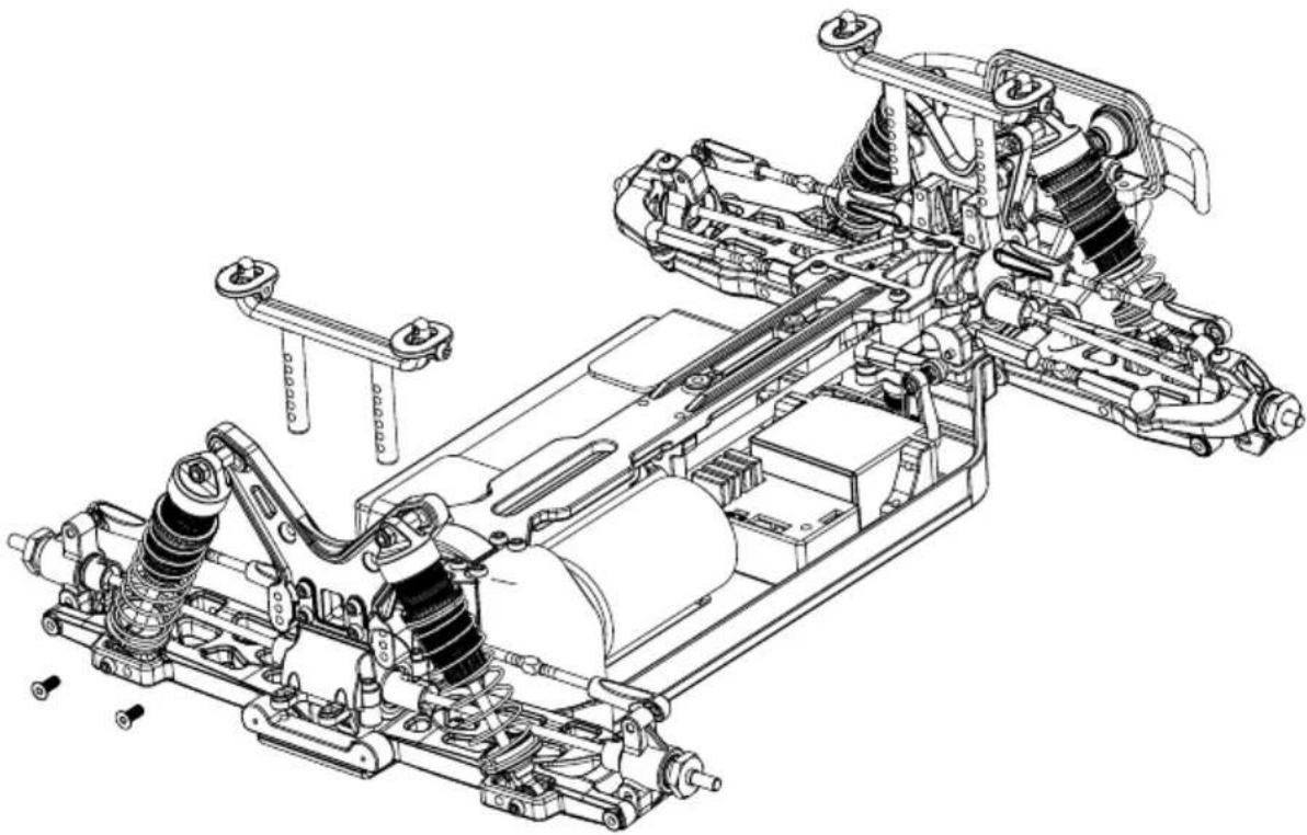
natural_image
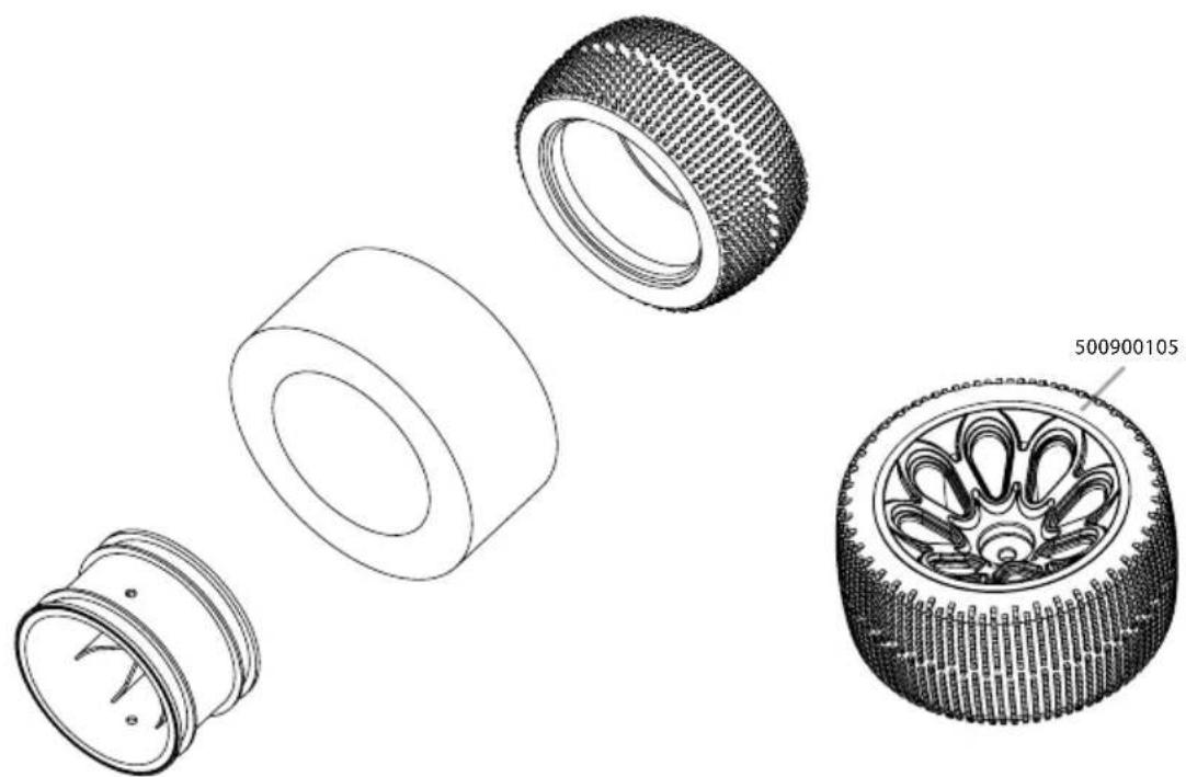
Technical line drawing of an automotive suspension system with springs, frame, and chassis components (no text or labels)- MONTAGE RÄDER • WHEEL ASSEMBLY
natural_image
Technical line drawings of four different mechanical components, showing exploded and assembled views (no text or symbols)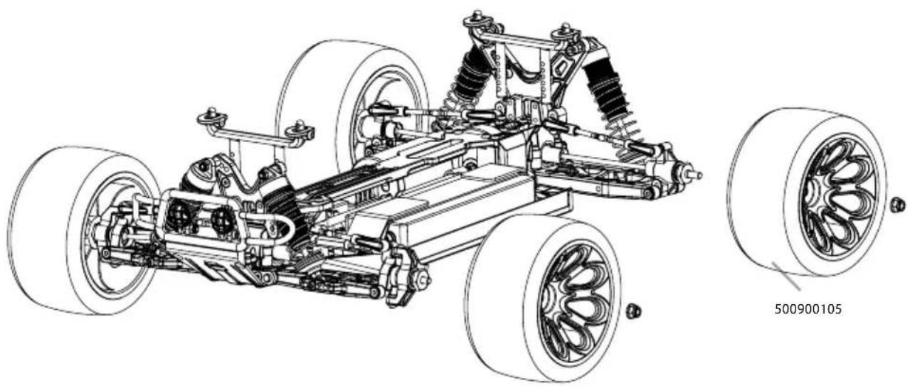
natural_image
Technical line drawing of a vehicle chassis with visible suspension components and two inset wheel assembly views (no text or symbols)- KAROSSERIE + SPOILER • BODY + WING
ERSATZTEILE • SPARE PARTS
ERSATZTEILE • SPARE PARTS
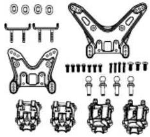
Shock tower / gear box set
natural_image
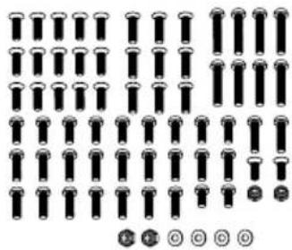
Technical diagram of mechanical components with no visible text or symbols500405421 Schrauben-Set „X10EB“ Screw set "X10EB"
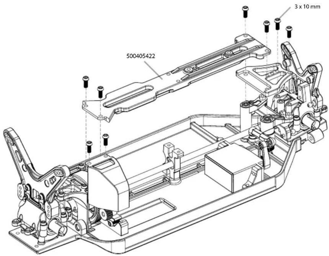
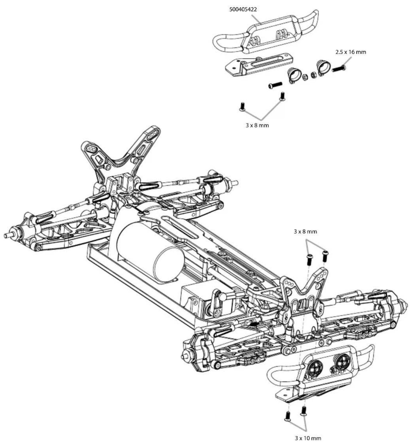
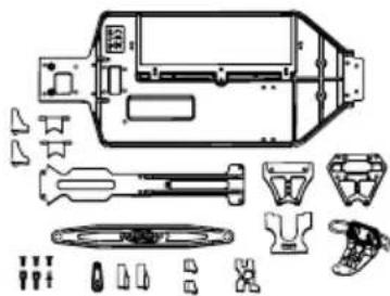
500405422 Chassis/Anbauteile-Set Chassis plates replacement set
natural_image
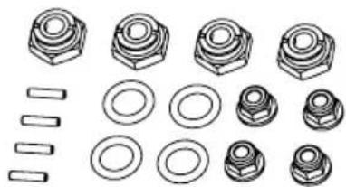
Technical line drawing of an electronic device with exploded view and component layout (no text or labels)500405445 4x Radmitnehmer-Set 4x Wheel nut set
natural_image
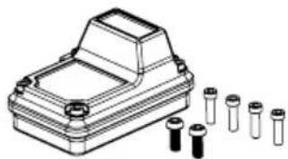
Collection of mechanical parts including bolts, rings, and fasteners (no text or symbols)500405691 X10 RC-Box X10 RC-Box
natural_image
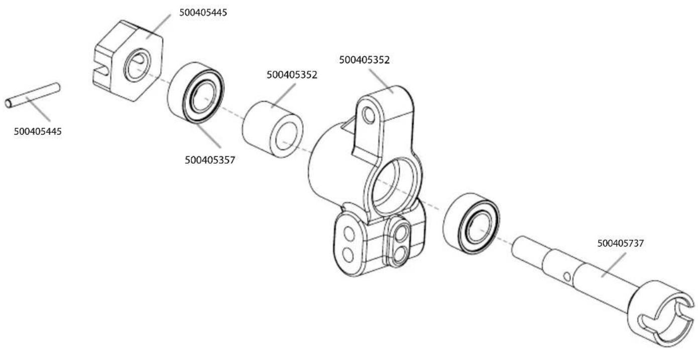
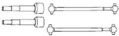
Technical line drawing of a mechanical housing with multiple cylindrical components (no text or symbols)500405737 2x Antriebswellen hi + Achsen 2x Rear dogbone + drive cup
natural_image
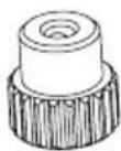
Technical line drawing of three mechanical shaft components with flanges (no text or symbols)500405738 Motorritzel 21 Z Pinion gear 21 T
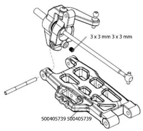
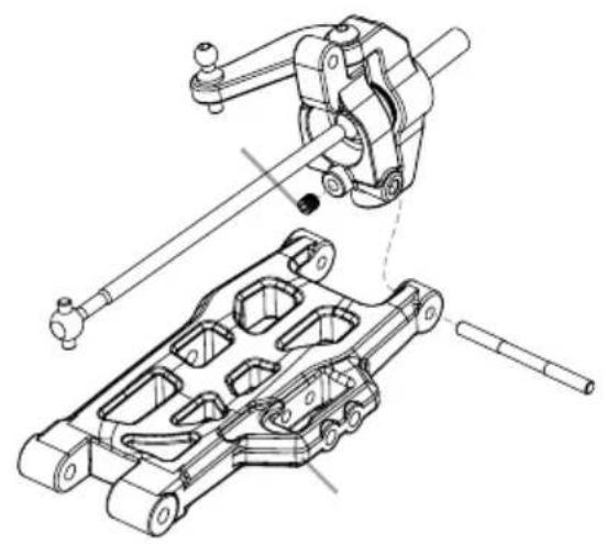
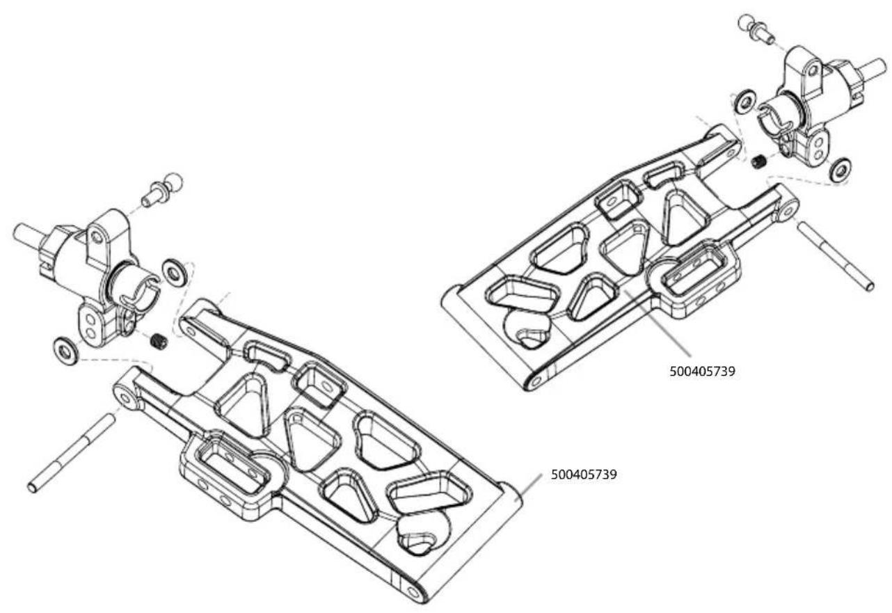
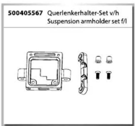
500405739 Querlenker Set Suspension arm
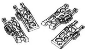
natural_image
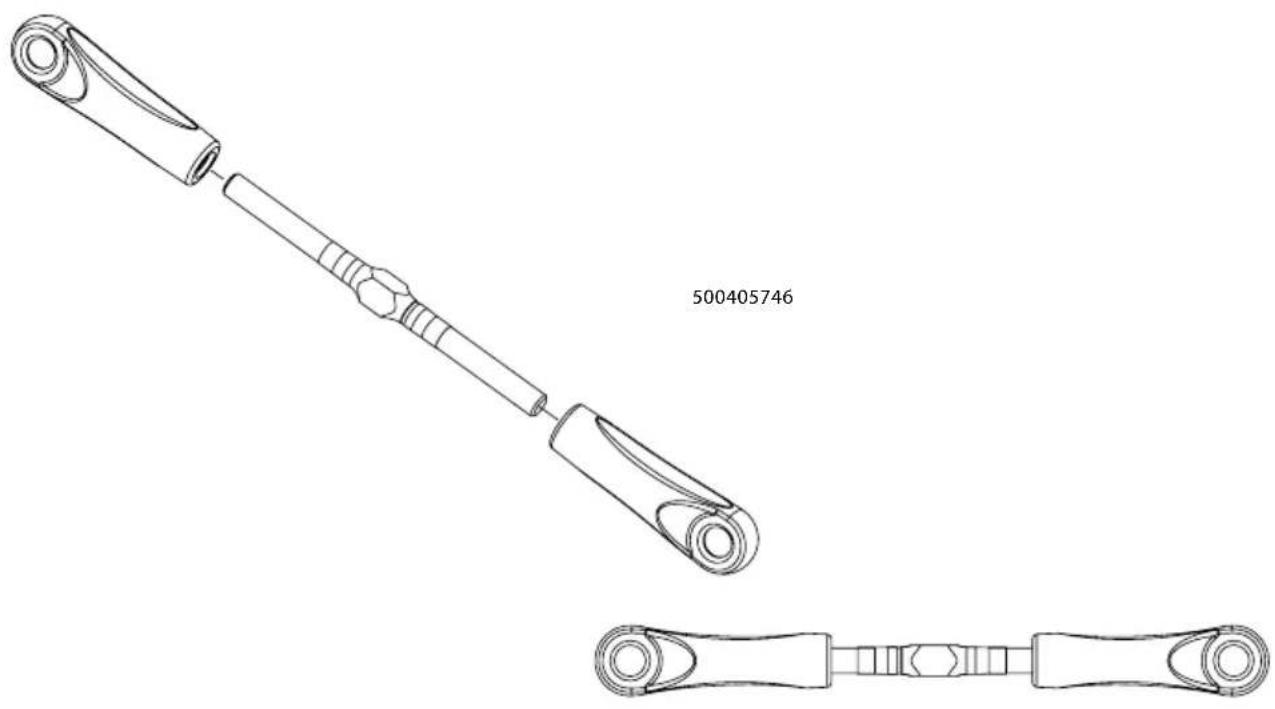
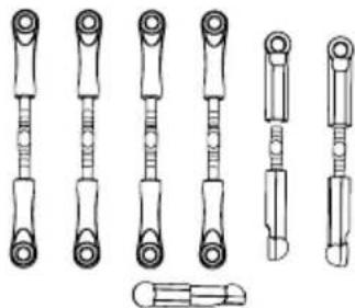
Technical line drawing of four mechanical components with no visible text or symbols500405746 7x Gestänge-Set 7x Full turnbuckle set
natural_image
Technical line drawings of various mechanical components (no text or symbols)natural_image
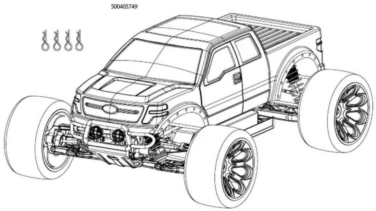
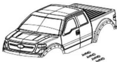
Technical line drawing of two mechanical shafts with flanges and end caps (no text or symbols)500405749 Karosserie Bad Buster Body Bad Buster
natural_image
Line drawing of a pickup truck chassis with visible frame structure (no text or symbols)natural_image
Technical line drawing of a mechanical component with two inset views (no text or symbols)ERSATZTEILE • SPARE PARTS
natural_image
Technical line drawing of mechanical components including brackets, rods, and circular fittings (no text or symbols)


- FR // Remarque importante
- AUFLADEN DES FAHRAKKUS
- EINLEGEN DER FAHRAKKUS
- BINDING
- Limited Warranty
- The Warranty does not cover:
- Declaration of conformity
- CONTENTS
- SCOPE OF DELIVERY
- TECHNICAL DATA
- SAFETY PRECAUTIONS
- Safety Instructions and Intended Use
- This model is not a toy!
- Before use, you must make sure of the following points:
- Pay attention to the charge level indication on your transmitter.
- SAFETY PRECAUTIONS LITHIUM BATTERIES
- General
- Warning notices
- Charging instructions
- Storage instructions
- General terms of guarantee
- Exclusion of liability
- 7.Disposal instructions
- CHASSIS
- REMOVING THE BODY
- CHARGE BATTERY PACK
- INSERTING THE DRIVE BATTERIES
- Advice
- YOUR TRANSMITTER
- Transmitter overview
- INSTALLING THE TRANSMITTER BATTERIES
- TURN ON THE RC SYSTEM
- CAUTION!
- Connecting transmitter and receiver:
- HOW TO CONTROL YOUR MODEL
- TROUBLESHOOTING
- Cher client
- Slipper-clutch adjustments
- MONTAGE SERVO • SERVO ASSEMBLY
- MONTAGE DIFFERENZIAL • DIFF ASSEMBLY
- GETRIEBEBOX • GEAR HOUSING
- DÄMPFERBRÜCKEN • SUSPENSION MOUNTS
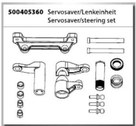
- MONTAGE LENKUNG • STEERING ASSEMBLY
- MONTAGE LENKUNG • STEERING ASSEMBLY
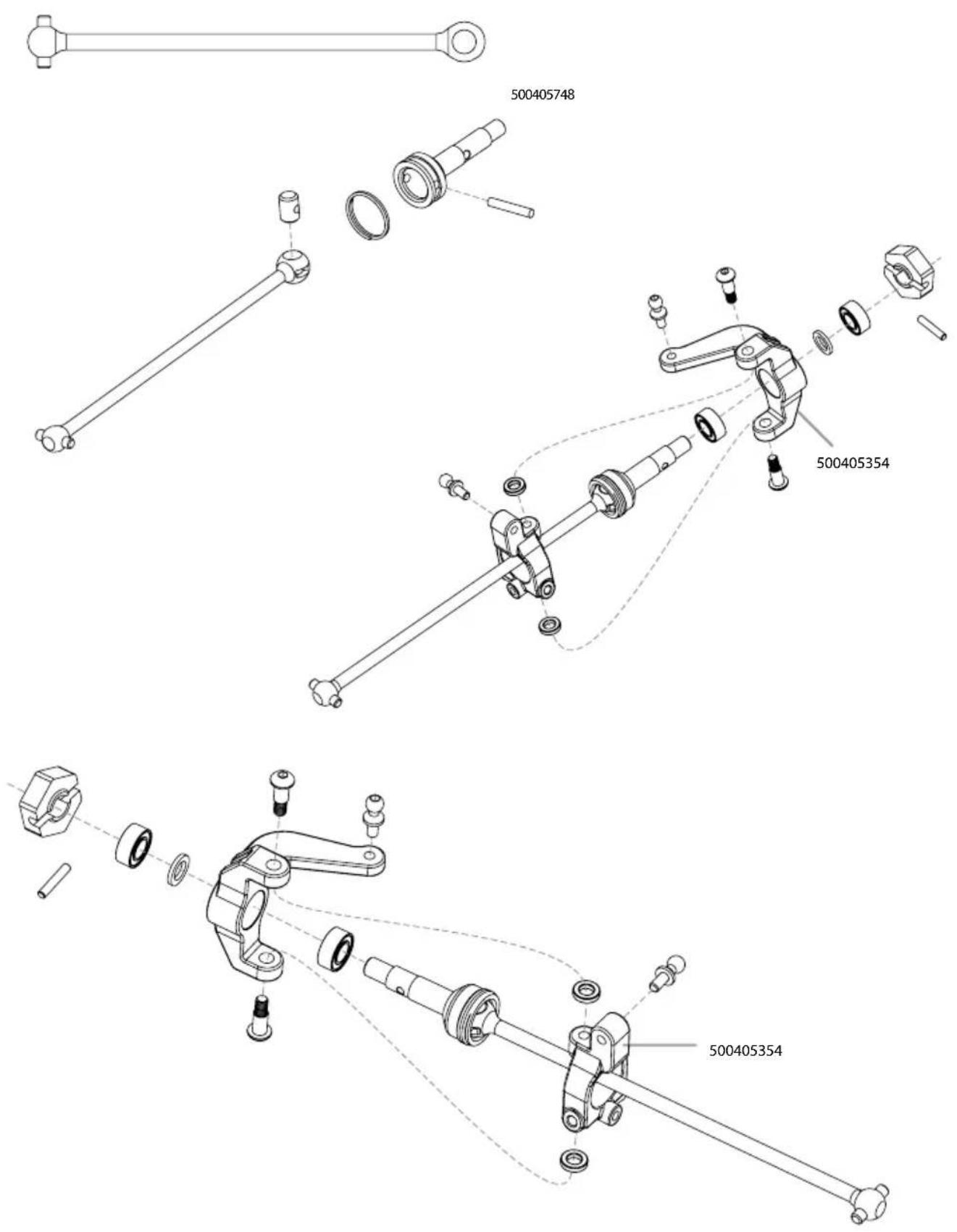
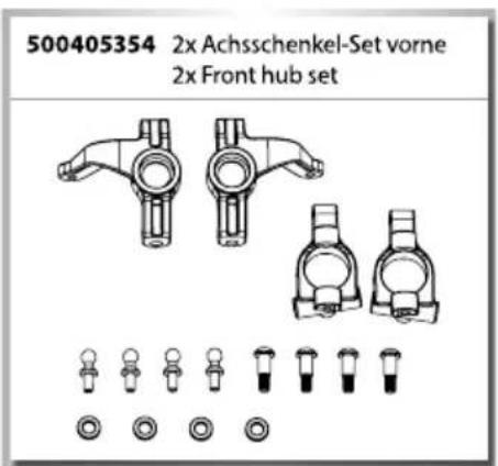
- MONTAGE ANTRIEB VORNE • FRONT DRIVE ASSEMBLY
- MONTAGE QUERLENKER • SUSPENSION ARMS ASSEMBLY
- MONTAGE LENKUNG • STEERING ASSEMBLY
- MONTAGE STABILISATOREN • SWAY BAR ASSEMBLY
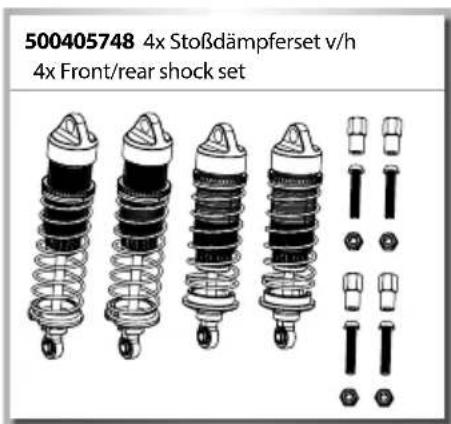
- MONTAGE STOSSDÄMPFER • SHOCK SET ASSEMBLY
- MONTAGE RC-SYSTEM • ASSEMBLY RC SYSTEM
- MONTAGE AKKUHALTER • BATTERY HOLDER ASSEMBLY
- MONTAGE LICHT • LIGHT ASSEMBLY
- ERSATZTEILE • SPARE PARTS
Brand : Carson
Model : X10 Bad Buster 2.0
Category : Remote control toy