
BFV146 - TV Stand SANUS - Free user manual and instructions
Find the device manual for free BFV146 SANUS in PDF.

| Product Type | TV cabinet with doors and shelves |
| Brand | Sanus |
| Model | BFV146 |
| Top shelf load capacity | 56.7 kg (125 lb) |
| Center shelf load capacity | 22.7 kg (50 lb) |
| Bottom shelf load capacity | 22.7 kg (50 lb) |
| Estimated dimensions (W x H x D) | 140 x 60 x 40 cm |
| Estimated weight | 30 kg |
| Materials | Particleboard panels, metal hardware |
| Color | Black or gray (depending on model) |
| Number of doors | 2 |
| Number of adjustable shelves | 1 fixed (center), 1 bottom |
| Assembly system | Cam screws and cam locks |
| Included accessories | Hardware, hinges, handles, Allen key |
| Optional accessories | Mounting bracket FMK056, anti-tip strap ELM701 |
| Main functions | Storage for TV and equipment, integrated cable management |
| Care and cleaning | Wipe with a soft, dry cloth. Avoid abrasive cleaners. |
| Safety instructions | Use the provided anti-tip strap to prevent tipping. Do not exceed maximum loads. |
| Repairability | Replacement parts available from the manufacturer (screws, cams, hinges, handles). |
| Warranty | 5-year limited warranty (subject to conditions) |
Frequently Asked Questions - BFV146 SANUS
User questions about BFV146 SANUS
0 question about this device. Answer the ones you know or ask your own.
Ask a new question about this device
Download the instructions for your TV Stand in PDF format for free! Find your manual BFV146 - SANUS and take your electronic device back in hand. On this page are published all the documents necessary for the use of your device. BFV146 by SANUS.
USER MANUAL BFV146 SANUS
natural_image
Line drawing of a modular kitchen cabinet with open door and internal compartments (no text or symbols)We are here to help! Please contact Customer Service with any questions.
Customer Service
Americas: 800-359-5520 • 651-484-7988 • info@sanus.com
Europe, Middle East, and Africa: +31 40 2324700 • europe.sanus@milestone.com
Asia Pacifi c: 86 755 8996 9226 • sanus.ap@milestone.com
SANUS • 2221 Hwy 36 West • Saint Paul, MN 55113 USA
©2011 Milestone AV Technologies, a Duchossois Group Company. All rights reserved. Sanus is a division of Milestone. All other brand names or marks are used for identification purposes and are trademarks of their respective owners.
English - How to use this manual
For best results, reference both the text and illustrations. Cut along the dashed lines to match your language with the illustrations.
OPT This item is optional English Text Pages 3-15
IMPORTANT SAFETY INSTRUCTIONS – SAVE THESE INSTRUCTIONS – PLEASE READ ENTIRE MANUAL PRIOR TO USE
Specifications
Weight capacities:
* Top [01] supports up to 56.7 kg (125 lbs.)
Middle shelf [05] supports up to 22.7 kg (50 lbs.)
- Lower shelf [06] supports up to 22.7 kg (50 lbs.)
CAUTION: Avoid potential personal injuries and property damage!
Do not use this product for any purpose not explicitly specified by manufacturer.
If you do not understand these instructions, or have doubts about the safety of the installation, assembly or use of this product, contact manufacturer Customer Service or call a qualified contractor.
Manufacturer is not responsible for damage or injury caused by incorrect assembly or use.
Required Tools
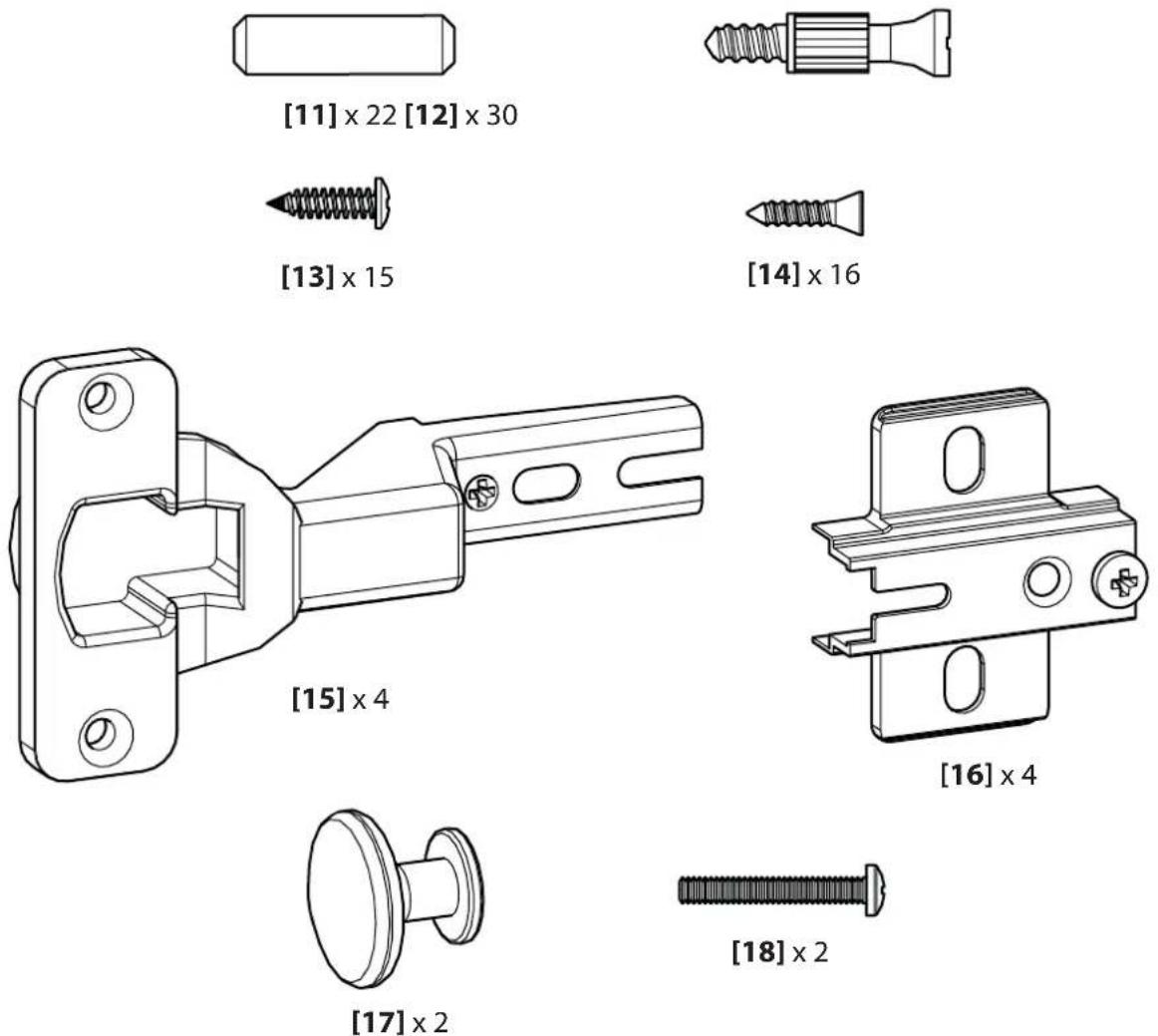
Supplied Parts and Hardware
WARNING: This product contains small items that could be a choking hazard if swallowed.
Before starting assembly, verify all parts are included and undamaged. If any parts are missing or damaged, do not return the damaged item to your dealer; contact Customer Service. Never use damaged parts!
![[01] x 1 [03] x 1 [02] x 1 [04L] x 1 [05] x 1 [07] x 1 [06] x̄ 1 [09] x 1 [08] x 2 [10] x 1 [04R] x 1](/content/2026/04/672551/images/bffe2aa30dee2b6fa76075c364770f4511dc4b1fda1fd856b81bfb0444177e66.jpg)
Parts for optional Pillar Kit (sold separately)
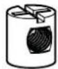
[19] × 4

[20] × 4 [21] × 4

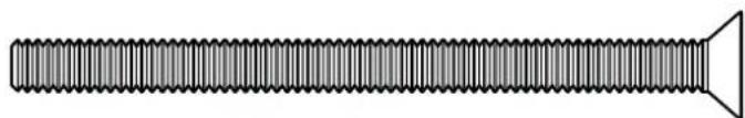
natural_image
Pure diagram of a screw with no text, numbers, or symbols[22] × 4
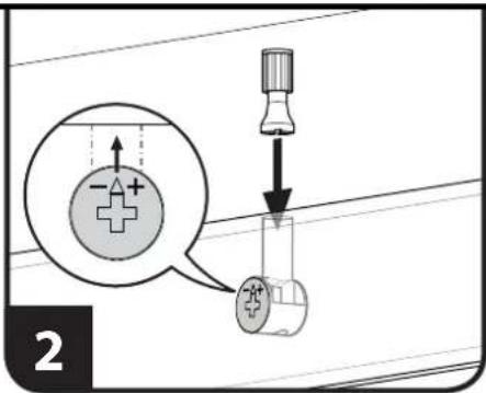
Using the Cam Screw [12] to assemble panels:
- Use a screw driver to turn cam screw into hole of the first panel to be connected until base of cam screw is flush with panel surface and screw is snug. The following pages will indicate correct hole locations. ⚠ CAUTION: Do not overtighten cam screws. Overtightening will damage the panel.
- Make sure arrow of cam lock is pointing towards hole in the edge of the second panel to be connected, then insert cam screw of first panel into cam lock hole of second panel.
- Turn cam lock clockwise until panels are secure.
![[12] 1](/content/2026/04/672551/images/cd21593b9fdfe771b2c20f94fbe2a576c5f4ddf60a21b3926fa7bb1ef25dbe35.jpg)
![SANUS BFV146 - Using the Cam Screw [12] to assemble panels: - 3](/content/2026/04/672551/images/0bbaee99d732fdf9c78bf0b2dbb97e084f60979d9f87dfebae49209d80ee6a64.jpg)
natural_image
Mechanical assembly diagram showing a shaft with a valve and rotating component (no text or symbols)1
![SANUS BFV146 - Using the Cam Screw [12] to assemble panels: - 4](/content/2026/04/672551/images/36359f3e289628d55020ae9f634971ca62bf9c9c0051d5c520ac0bf1b579fb0c.jpg)
![Install cam screws [12] and dowels [11] into bottom side of middle panel [05] and top side of bottom panel [06]. [12] [11] [12] [11] [12] [11] [12] [06] [05] [12] [11]](/content/2026/04/672551/images/119a6906dbd29bafdd64ef6b695aa8e4c1b39bb70e305b80adb93b9de9f5e0fd.jpg)
2
![SANUS BFV146 - Using the Cam Screw [12] to assemble panels: - 6](/content/2026/04/672551/images/9d10a6a82c9ca5cd87ca3c388137ab06d2c579c5a5ff6532a379e34d02ab4a4a.jpg)
![Assemble bottom panel [06], middle divider [07], and middle panel [05]. Tighten cam locks. NOTE: Finished edge of panel will be to the front. [06] [07] [05]](/content/2026/04/672551/images/f74a89d1930ee5c9a9393cb1f66be8ffd225486fe8a5b939d340f562a3a27a33.jpg)
![[09] [11] [12] Install cam screws [12] and dowels [11] into lower front brace panel [09]. Add lower front brace panel [09] to bottom panel [06] and tighten cam locks. [09] [11] [12] [11] [06] [07] [05]](/content/2026/04/672551/images/4b06dad10b5cc8b0a56dc2160ef4cb368ef9aaffb91b34fd9354ce821cec0109.jpg)
4
![Install cam screws [12] and dowels [11] into the insides of the left [04L] and right [04R] side panels. [04R] [11] [12] [04R] [04L]](/content/2026/04/672551/images/5625af2bc20fcd1d2b21cb68cae96bed36fc1abf2d2ae4636548a205e81efe8f.jpg)
5
Install middle assembly [05], [06], [07], and [09] onto left side panel assembly [04L]. Tighten all cam locks.
![[09] [07] [06] [05] [04L]](/content/2026/04/672551/images/2bc044555c319bf99131f3af2205c5db8354dcb2a8a27c8576f8e40691ad0213.jpg)
6
Install rear brace [03] onto left [04L] side panel. The notch in the rear brace [03] will be to the back side and towards the bottom of the unit. Tighten the cam lock.
![[03] [04L]](/content/2026/04/672551/images/6b3ef184d6b42a465304e655458d6bed6053b491e0bef578bd696129ead144fd.jpg)
Install front brace [02] and right [04R] side panel onto assembly. Tighten all cam locks.
![[04R] [02]](/content/2026/04/672551/images/dc16b4f7121d2d01f7aac70ec4496afcde9122be6eaee29a4064ba1e02098eca.jpg)
8
Check that all cam locks are secure and stand assembly upright.
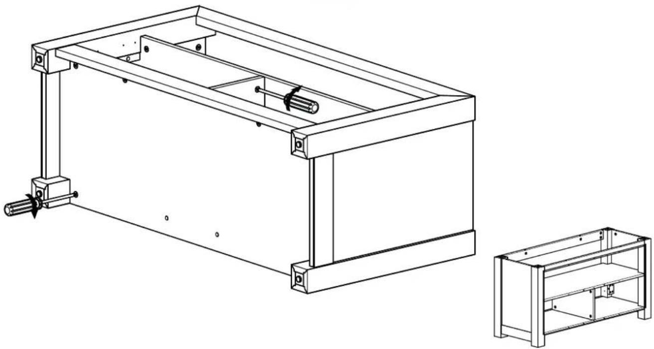
natural_image
Technical line drawing of a mechanical frame assembly with two views: top shows internal components, bottom shows exterior view (no text or symbols)![Insert dowels [11] into corners. [11]](/content/2026/04/672551/images/39fb048a69143a8c792385791a25cfa6f93e135cd3d40780a4904efbfd567b91.jpg)
10
![Install cam screws [12] into underside of top panel [01]. [12] [01]](/content/2026/04/672551/images/db0fd047b0c50a3d35ea3c86eadd474d6b0845e2e0673e3238bd443000fe0e94.jpg)
Fit top panel [01] onto base assembly. Tighten cam locks.
![[01] Fit top panel [01] onto base assembly. Tighten cam locks.](/content/2026/04/672551/images/ecac01312d4e847169b421870a0062faee95ed060098cc2bbf261c01005090e8.jpg)
12
![Install back panel [10] onto back of table assembly with screws [13]. [10] [13]](/content/2026/04/672551/images/b03d35bbae6588e01cf5bcf30b341a80461a90c084e68eaea2251827a523b293.jpg)
![Install two door hinges [15] to each door [08] with screws [14]. Install door knobs [17] to each door with screws [18]. [17] [18] [14] [15] [08]](/content/2026/04/672551/images/1ebebf9438e5e9dcc26a61f5b231f58a60cbbebf8ca2971fa22b8c6037face33.jpg)
14
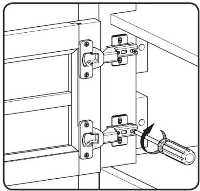
![Install hinge plates [16] to table assembly frame with screws [14].](/content/2026/04/672551/images/3a98e1d6a37a3524cf299c6857055d81eb0244768349c293b6700445ded9bec4.jpg)
Mount door assemblies onto hinge plates [16] and secure with hinge plate screws. Doors may be adjusted if required.
![[16]](/content/2026/04/672551/images/4a084fc40d4b9bb8ad02fa03896264a2f208b1275625598105855a9c29d82699.jpg)
natural_image
Technical line drawing of a door latch mechanism with screwdriver (no text or symbols)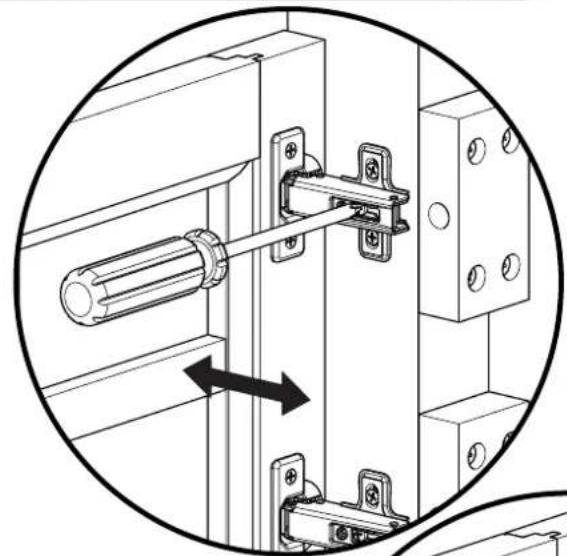
natural_image
Technical diagram of a mechanical latch assembly with a cylindrical component inserted, showing alignment and mounting details (no text or symbols)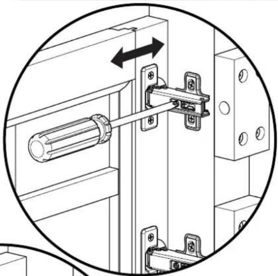
natural_image
Technical diagram of a mechanical latch assembly with mounting brackets and a cylindrical component, enclosed in a circular arrow (no text or symbols)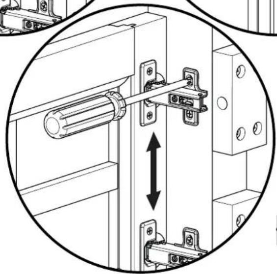
natural_image
Technical diagram of a mechanical latch assembly with mounting brackets and a vertical double-headed arrow indicating motion (no text or symbols present)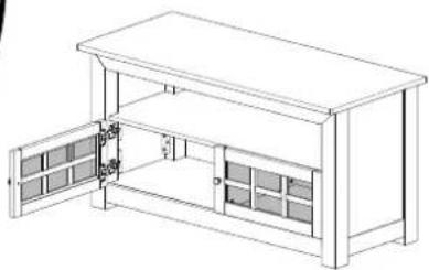
natural_image
Line drawing of a multi-level cabinet or enclosure with open doors and internal compartments (no text or symbols)NOTE: The M4 allen key and pillar bracket are included with the FMK056 pillar kit mount (purchased separately).
![NOTE: The M4 allen key and pillar bracket are included with the FMK056 pillar kit mount (purchased separately). [19] [20] [21] [22]](/content/2026/04/672551/images/787c045fe6fec5fdcbf37a075512161af078cf12c15d0f7d7cf20c063b293d8d.jpg)
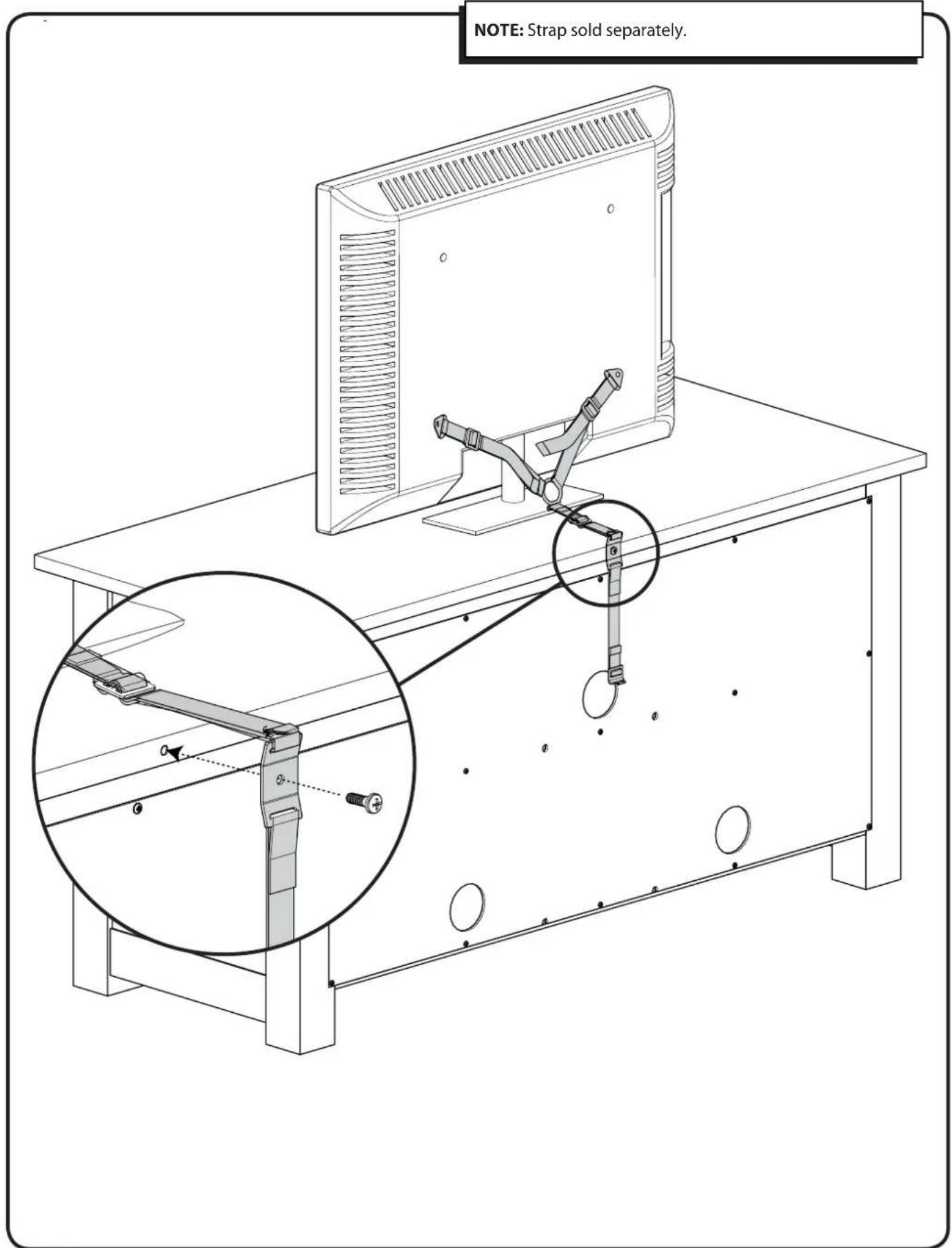
NOTE: Strap sold separately.
SANUS®
Français
CONSIGNES DE SÉCURITÉ IMPORTANTES – CONSERVEZ CES INSTRUCTIONS – VEUILLEZ LIRE ATTENTIVEMENT LE MANUEL AVANT D'UTILISER CE PRODUIT
Milestone AV Technologies and its affiliated corporations and subsidiaries (collectively, "Milestone"), intend to make this manual accurate and complete. However, Milestone makes no claim that the information contained herein covers all details, conditions, or variations. Nor does it provide for every possible contingency in connection with the installation or use of this product. The information contained in this document is subject to change without notice or obligation of any kind. Milestone makes no representation of warranty, expressed or implied, regarding the information contained herein. Milestone assumes no responsibility for accuracy, completeness or sufficiency of the information contained in this document.