
BFV348 - TV Stand SANUS - Free user manual and instructions
Find the device manual for free BFV348 SANUS in PDF.

User questions about BFV348 SANUS
0 question about this device. Answer the ones you know or ask your own.
Ask a new question about this device
Download the instructions for your TV Stand in PDF format for free! Find your manual BFV348 - SANUS and take your electronic device back in hand. On this page are published all the documents necessary for the use of your device. BFV348 by SANUS.
USER MANUAL BFV348 SANUS
natural_image
3D wireframe model of a black cabinet with four legs and two doors, showing interior compartments (no text or symbols)We are here to help!
Please contact Customer Service with any questions.
Customer Service
Americas: 1-800-359-5520 · 925-225-6013 · info@sanus.com
Europe, Middle East, and Africa: +31 (0) 495 580 852 • europe.sanus@milestone.com
Asia Pacifi c: 86 755 8996 9226 · sanus.ap@milestone.com
SANUS • 6436 City West Parkway • Eden Prairie • MN 55344
©2012 Milestone AV Technologies, a Duchossois Group Company. All rights reserved. Sanus is a division of Milestone. All other brand names or marks are used for identification purposes and are trademarks of their respective owners.
English - How to use this manual
For best results, reference both the text and illustrations.
OR Select one item or the other.
OPT This item is optional
English Text Pages 3-9
IMPORTANT SAFETY INSTRUCTIONS – SAVE THESE INSTRUCTIONS – PLEASE READ ENTIRE MANUAL PRIOR TO USE
Specifications
Weight capacity-DO NOT EXCEED:
■ Top shelf: 59 kg (130 lb.)
Middle shelves: 23 kg (50 lb.)
Bottom shelf: 34 kg (75 lb.)
CAUTION: Avoid potential personal injuries and property damage!
Do not use this product for any purpose not explicitly specified by manufacturer.
If you do not understand these instructions, or have doubts about the safety of the assembly or use of this product, contact Customer Service or call a qualified contractor.
Manufacturer is not responsible for damage or injury caused by incorrect assembly or use.
Before You Begin
natural_image
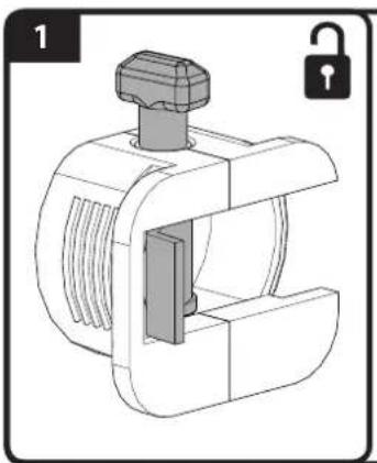
Technical illustration of a mechanical clamp or connector with a lock icon (no text or symbols)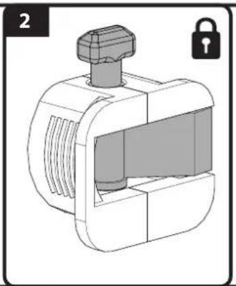
natural_image
Technical illustration of a mechanical valve or fitting component with a lock icon (no text or symbols)For step 6: Before installing the center divider [06] and the top [04], check that the cams (C) are open. Cams are open when the tab is NOT flush with the front surface fo the cam. After you have installed the top [04], lock the cams to secure the top. Cams are closed when the tab is flush with the front surface of the cam.
Image 1 shows the cam in the open position.
Image 2 shows the cam closed.
natural_image
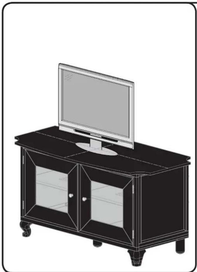
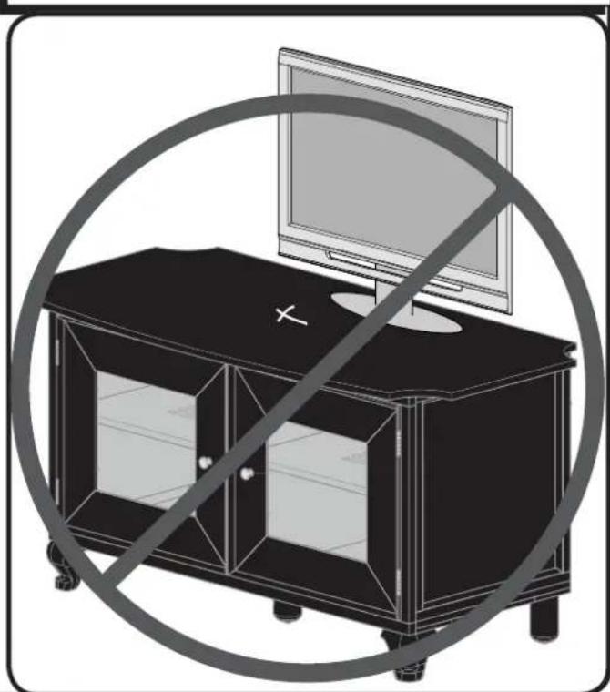
Line drawing of a modern TV set with a monitor and glass doors (no text or symbols)CAUTION: This product is designed for use with flat panel TVs ONLY.
To prevent tipping, be sure to center your fl at panel TV (NO CRTs) on top of your furniture.
natural_image
Illustration of a TV set with a monitor and a cross symbol, enclosed in a circular border (no text or symbols)⚠ WARNING: This product contains small items that could be a choking hazard if swallowed.
Before starting assembly, verify all parts are included and undamaged. If any parts are missing or damaged, do not return the damaged item to your dealer; contact Customer Service. Never use damaged parts!
natural_image
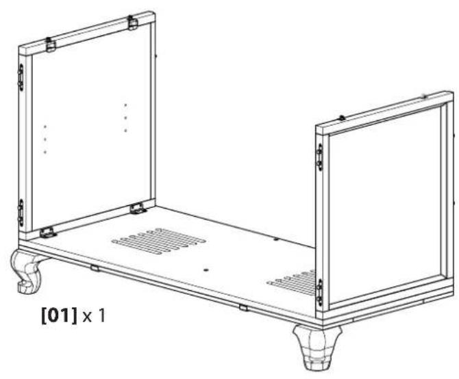
Technical line drawing of a two-panel metal frame structure with mounting feet and ventilation grilles (no text or symbols)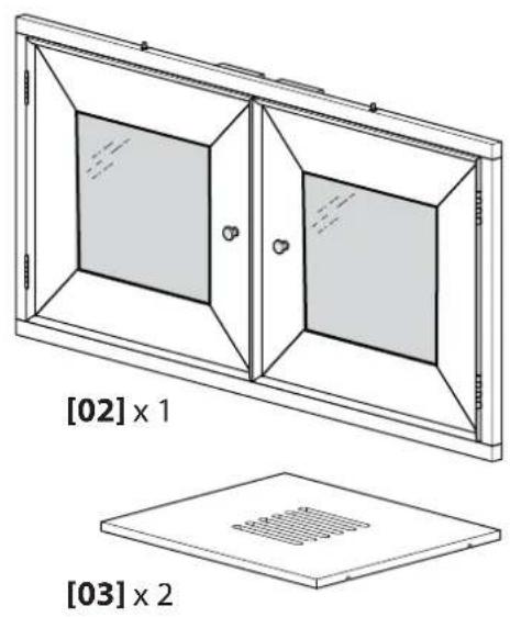
natural_image
Technical diagram of a two-panel door frame with labeled cross-sections [02] x 1 and [03] x 2, showing internal compartments and mounting holes (no text or symbols beyond labels)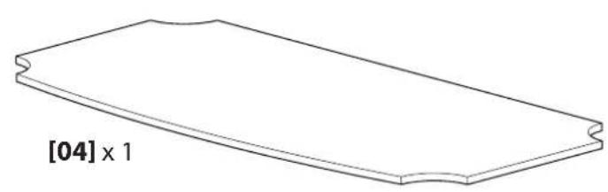
natural_image
Simple line drawing of a rectangular object with a notch, labeled [04] x 1 (no other text or symbols)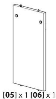
natural_image
Simple 3D diagram of a rectangular panel with two small circular holes, labeled [05] x 1 and [06] x 1 (no text or symbols on the panel itself)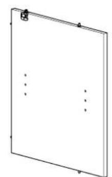
natural_image
Simple 3D rectangular panel with corner markers and three vertical dotted lines (no text or symbols)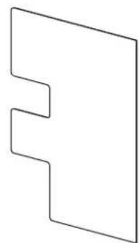
natural_image
Pure geometric shape resembling a stylized letter 'E' or bracket (no text or symbols)
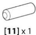
[07] × 2
1 Unfold Sides
![Lay the bottom and side panel assembly [01] back side down on the floor. Lift open the side panels of the assembly [01]. [01]](/content/2026/04/672545/images/8131f08e0af53533fae9c76b55d8b6031163c6102159529dba49139539cab3b8.jpg)
2 Attach Legs
![Screw the legs [09] into place, as shown. NOTE: Each leg [09] has an adjustable foot (F). Be sure that each foot makes contact with the floor when you turn the unit upright in the next step. [09] [01] (F) [01] [09] [F]](/content/2026/04/672545/images/41dfb16c352fb635ae14b469b6e232dbe97b655b56af529e9d8629c13b8ca32e.jpg)
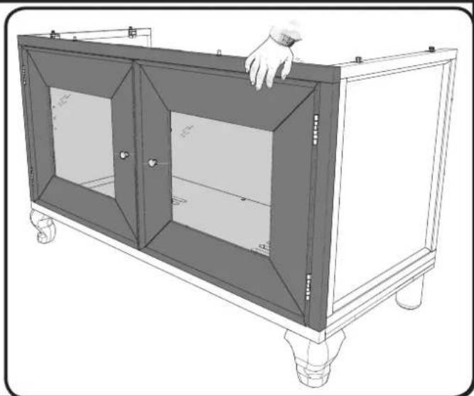
3 Attach Front Frame and Doors
![[01] [02]](/content/2026/04/672545/images/79fe371bafd6165e52f4e8824ed633d4f0f004ee6a764ba800f27209bdcd2312.jpg)
Set the front frame [02] on top of the side panel assembly [01]. Push the front frame assembly [02] toward the feet of the unit.
Turn the unit upright. Push down on the top of the front frame [02] to ensure it is fully engaged with the bottom panel [01].
Check to see that each leg makes contact with the floor. Adjust if necessary.
natural_image
Line drawing of a cabinet with handle and wheels, no text or symbols present4 Attach Center Divider
![[01] [05] [06]](/content/2026/04/672545/images/10f5fc51b425e3abc061b7ab2041ff9e4768890da2240f7bedf549a8d0a5ea9d.jpg)
Attach the center divider [06] to the middle back panel [05]. Then attach both to the bottom assembly [01].
![[06] [05]](/content/2026/04/672545/images/988acff32108b91f573a35fa1c56988e553b8c59d1bb2683e332f55e13e5d801.jpg)
5 Attach Shelves
![[01] [03] [06] Insert shelf pins [10] into the sides [01] and center divider [06]. Lower shelves [03] onto the pins. [03] [10]](/content/2026/04/672545/images/f4cc22c20c50f46ce01f0bef6429e4a75244a8ccdc190d625c77d0343bdf7a78.jpg)
6 Attach Top
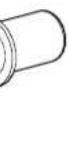
![Check that the cams (C) that connect these parts are open. Position the top [04] onto sides [01], front [02] and middle back [05]. Align the holes in the top [04] with the cams and dowels (C, D, [08], [11]). Close the cams (C). For more information on cams, see Before You Begin on page 3.](/content/2026/04/672545/images/aa137ee45fe500dbb525a9e5a47269668a01a262a48e526f07d7312a0963d2a9.jpg)
7 Attach Back Panels
![Attach the back panels [07] to the back side of the frame [01]. Secure with tabs (L). [07] [01] [07] (L)](/content/2026/04/672545/images/d95891c013fd12bc03cb620a3d611e76db6999de05d1460a9907e8ed3fa1b997.jpg)
Care and Accessories
For wood with a natural finish, dust regularly with a soft dry cloth. When needed, wipe with a moist cloth, not wet, and wipe dry.

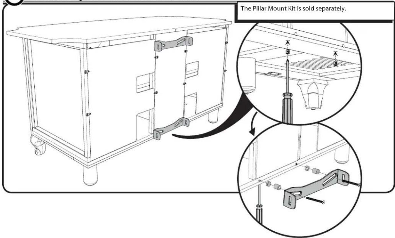
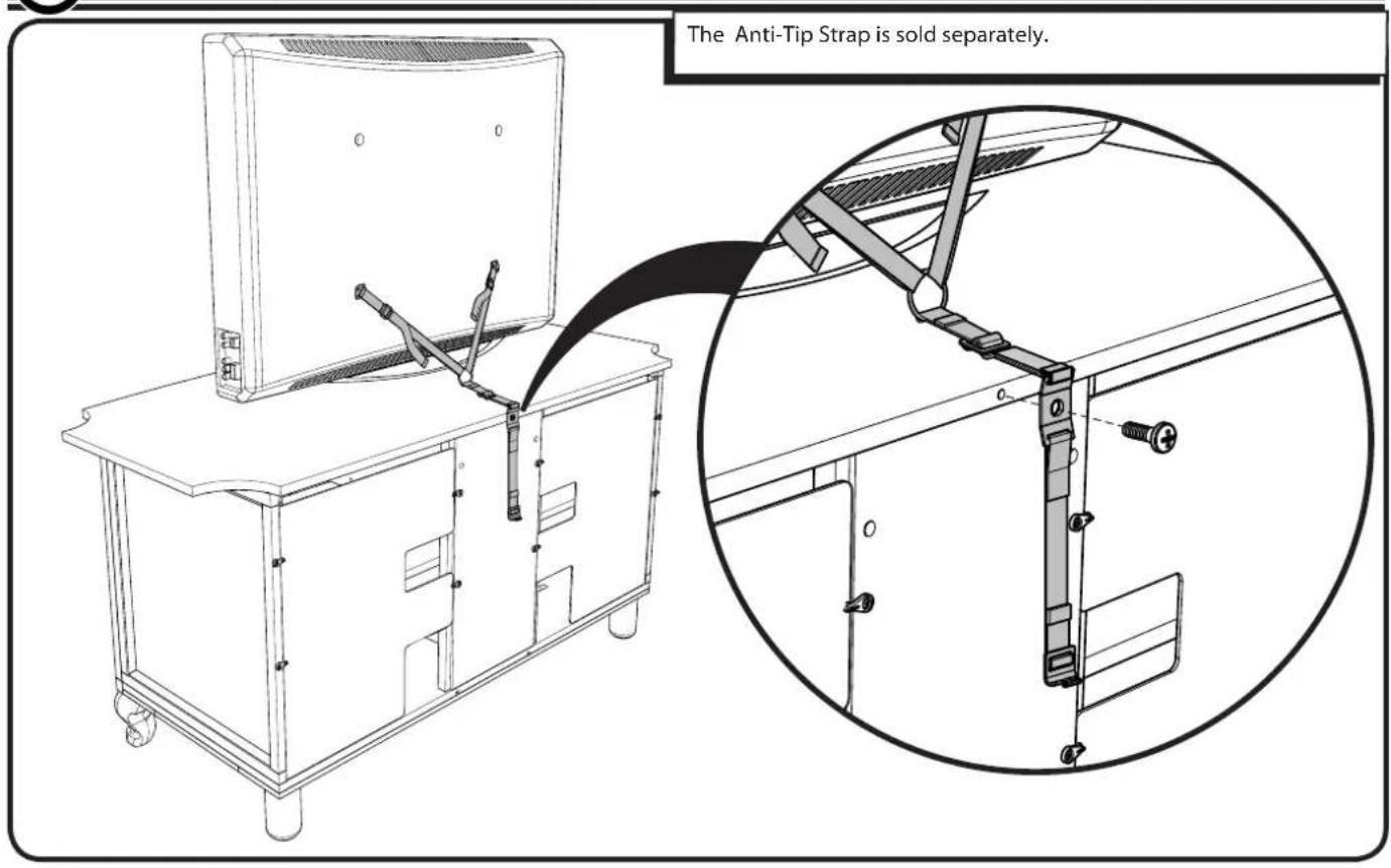
Attach Optional Pillar Mount
SANUS®
Français
CONSIGNES DE SÉCURITÉ IMPORTANTES – CONSERVEZ CES INSTRUCTIONS – VEUILLEZ LIRE ATTENTIVEMENT LE MANUEL AVANT D'UTILISER CE PRODUIT
Milestone AV Technologies and its affiliated corporations and subsidiaries (collectively, "Milestone"), intend to make this manual accurate and complete. However, Milestone makes no claim that the information contained herein covers all details, conditions, or variations. Nor does it provide for every possible contingency in connection with the installation or use of this product. The information contained in this document is subject to change without notice or obligation of any kind. Milestone makes no representation of warranty, expressed or implied, regarding the information contained herein. Milestone assumes no responsibility for accuracy, completeness or sufficiency of the information contained in this document.