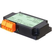
EMMOD205 - Electronic module Gossen Metrawatt - Free user manual and instructions
Find the device manual for free EMMOD205 Gossen Metrawatt in PDF.


User questions about EMMOD205 Gossen Metrawatt
0 question about this device. Answer the ones you know or ask your own.
Ask a new question about this device
Download the instructions for your Electronic module in PDF format for free! Find your manual EMMOD205 - Gossen Metrawatt and take your electronic device back in hand. On this page are published all the documents necessary for the use of your device. EMMOD205 by Gossen Metrawatt.
USER MANUAL EMMOD205 Gossen Metrawatt
CH-5610 Wohlen/Switzerland
Telefon +41 56 618 21 11
Telefax +41 56 618 35 35
e-mail: info@camillebauer.com
http://www.camillebauer.com
EMMOD205 Bdfe 157 132-03 06.10


Manufacturer: Switzerland
Address: CH-5610 Wohlen
The above mentioned product has been manufactured according to the regulations of the following European directives proven through compliance with the following standards:
EN/Norm/Standard IEC/Norm/Standard
EN 61010-1:2001 IEC 61010-1:2001
Ort, Datum /
Leiter Technik / Head of engineering Qualitätsmanager / Quality manager
Camille Bauer SA
Aargauerstrasse 7
Appuyer la touche Ⓟ > 2 sec.
Manufacturer: Switzerland
Address: CH-5610 Wohlen
The above mentioned product has been manufactured according to the regulations of the following European directives proven through compliance with the following standards:
Leiter Technik / Head of engineering
Qualitätsmanager / Quality manager
Operating Instructions Extension module LON for A2xx devices
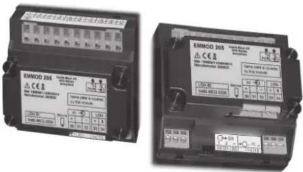
EMMOD 205
CAMILLE BAUER
text_image
EMMOD 205 Cable Baut. 493 EMINI METER Subschnitt Max: 16MEN01102843074 Manufacturer: 300K30 Name: GPTM 6, 20-100 by this module: LOW ID S480 8502-0285 Status Bv LON + - 30 51 30 33 34 3Camille Bauer Ltd
Aargauerstrasse 7
CH-5610 Wohlen/Switzerland
Phone +41 56 618 21 11
Fax +41 56 618 35 35
e-mail: info@camillebauer.com
http://www.camillebauer.com
EMMOD205 Bdfe 157 132-01 08.08


The instruments must only be disposed of in the correct way!
Safety notes

Installation and commissioning should only be carried out by trained personnel.
Check the following points before commissioning:
- that the maximum values for all the connections are not exceeded, see the "Technical data" section,
- that the connection wires are not damaged, and that they are not live during wiring.
The instrument must be taken out of service if safe operation is no longer possible (e.g. visible damage). In this case, all the connections must be switched off. The instrument must be returned to the factory or to an authorized service dealer.

Do not touch the printed circuit or contacts! Electrostatic charge can damage electronic components.
Unauthorized repair or alteration of the unit invalidates the warranty.
Contents
- Brief description .... 19
- Scope of delivery 19
- Technical data 19
- Assembly/disassembly 20
- Connections of the device 21
- Bus wiring LON 21
- Display and operating elements 22
- Network variables and configuration parameters ..... 22
- Programming of digital input/output 26
- Declaration of conformity 27
1. Brief description
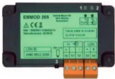
The extension module EMMOD 205 supplements the functionality and fl exibility of the basic device A2xx and enables the communication via LON interface. Data exchange with a control system may be done by means of the LONTALK® protocol. The module can be retro-fi tted without alteration of the basic unit and is available in two different versions.
The version type A (156 647) is optimized for the communication with the summation stations U160x of Gossen-Metrawatt and emulates the functionality of a energy meter U1387, as well of Gossen-Metrawatt. It provides a digital output which can be used to signal alarm limit violations.
The version type E (156 639) is suited for direct application in LON networks. The most important measured quantities and meter contents of the basic device are provided via the interface. The digital input allows to synchronize the intervals of the mean-value calculation. It may also be used for high/low tariff switching of the meters.
The basic device A2xx can not be parametrized via LON interface. The display unit has to be configured via the keys.
Alternatively an EMMOD 201 (Modbus) or EMMOD 203 (Ethernet) may be plugged on temporary to allow the parametrization of the basic unit by means of the PC software A200plus.
2. Scope of delivery
1 Extension module EMMOD 205
4 Plastic rivets
1 Operating instruction German/French/English
Additional label each for input and output/power supply
3. Technical data
Power supply
The EMMOD 205 is powered by the basic unit A2xx. The power consumption of the basic unit is increased by approx. 0.5 VA when the EMMOD 203 is connected.
Environmental conditions
Operating temperature: -10 to +55 °C
Storage temperature: -25 to +70 °C
Relative humidity of
annual mean: ≤ 75%
Altitude: 2000 m max.
Indoor use statement!
Communication
Interface: LON
Protocol: LONTALK®
Transmission medium: Echelon FTT-10A transceiver, transformer-coupled, polarity protected, twisted two-wire cable
Transmission speed: 78 kBit/s
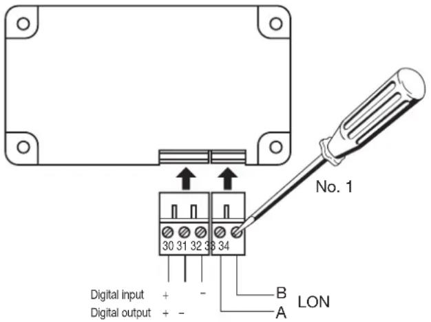
Connections: Pluggable screw terminals
Digital input (type E)
Function: Synchronization clock for mean-values or switching of high/low tariff for energy meters
Contact supply: internally 5 V / 2.2 kΩ
External connection: potential-free contact
Contact open: Resting state, high tariff
Contact closed: Pulse, low tariff, LED "IN" flashes
Minimum pulse width: 150 ms
Digital output (type A)
Function: Alarm limit monitoring
Isolation to all
other circuits: 500 V AC
Maximum values: 125 V (+ 25%), 30 mA
4. Assembly/disassembly
The basic unit A2xx to extend must have a firmware version 4.00 or higher.

Switch-off basic unit A2xx.
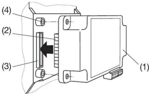
Simply plug-in the extension module (1) at the back of the basic instrument (fi g. 1). Please ensure that the plug (2) and socket (3) are aligned correctly.

Note! Do not touch the printed circuit or contacts!
Electrostatic charge can damage electronic components.
text_image
(1) (2) (3) (4)Fig. 1
reverse
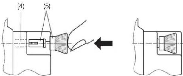
To fix the module mechanically, insert the four plastic clips supplied (5) in the fi xing holes (4) (fi g. 2).
text_image
(4) (5)Fig. 2
Affi x the additional label: inputs and outputs/power supply as in fig. 3.
text_image
EMMOD 205 EMMOD 205 EMMOD 205 EMMOD 205 EMMOD 205 EMMOD 205 EMMOD 205 EMMOD 205 EMMOD 205 EMMOD 205 EMMOD 205 EMMOD 205 EMMOD 205 EMMOD 206 EMMOD 206 EMMOD 206 EMMOD 206 EMMOD 206 EMMOD 206 EMMOD 206 EMMOD 206 EMMOD 206 EMMOD 206 EMMOD 206 EMMOD 206 EMMOD 206 EMMMOD 206 EMMMOD 206 EMMMOD 206 EMMMOD 206 EMMMOD 206 EMMMOD 206 EMMMOD 206 EMMMOD 206 EMMMOD 206 EMMMOD 206 EMMMOD 206 EMMMOD 206 EMMMOD 207 EMMMOD 207 EMMMOD 207 EMMMOD 207 EMMMOD 207 EMMMOD 207 EMMMOD 207 EMMMOD 207 EMMMOD 207 EMMMOD 207 EMMMOD 207 EMMMOD 207 EMMMOD 207 EMMOD 207 EMMOD 207 EMMOD 207 EMMOD 207 EMMOD 207 EMMOD 207 EMMOD 207 EMMOD 207 EMMOD 207 EMMOD 207 EMMOD 207 EMMOD 207 EMMOD 208 EMMOD 208 EMMOD 208 EMMOD 208 EMMOD 208 EMMOD 208 EMMOD 208 EMMOD 208 EMMOD 208 EMMOD 208 EMMOD 208 EMMOD 208 EMMOD 208 EMMMOD 214Fig. 3
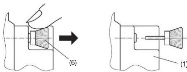
To release the module, pull out the plastic clips by the knurled knob (6) with the fingers (fig. 4). The extension module (1) can now be removed.
text_image
(6) (1)Fig. 4
- Connections of the device
text_image
No. 1 30 31 32 33 34 Digital input + Digital output + - B A LONFig. 5
Maximum cable length
| Bus Network (bus terminator at both ends) | Free Topologies (bus terminator at one end only) | |
| JY (ST) Y 2 x 2 x 0.8 mm | 900 m 500 m | max. 320 m from device to device |
| Level IV, 22AWG 1400 m | 500 m | max. 400 m from device to device |
| Belden 8471 2700 m | 500 m | max. 400 m from device to device |
| Belden 85102 2700 m | 500 m |
Indicated values apply to overall cable length in combination with the FTT-10A transceiver.
6. Bus wiring LON
The most commonly utilized transmission medium for industrial and building management applications is the twisted pair cable with copper conductors which is used together with the electrically isolated FTT-10A transceiver. Both cable conductors can be connected to either terminal which eliminates the possibility of pole reversal during installation. Maximum transmission distances depend upon the electrical characteristics of the cable and network topology. It must therefore be strictly observed that the utilized cable fulfi lls the required specifi cations, and that the same cable type is used throughout any given bus segment in order to prevent refl ections.
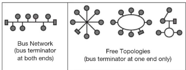
Network topologies:
text_image
Bus Network (bus terminator at both ends) Free Topologies (bus terminator at one end only)Fig. 6
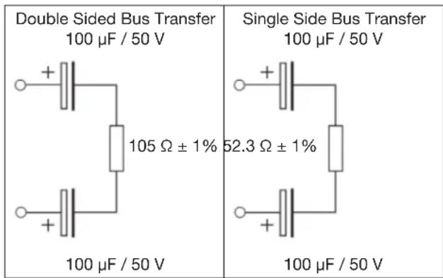
Devices are connected in parallel, one after the other, in bus networks. A bus terminator must be included at each end. Wiring with free topologies requires only one bus terminator, but transmission distances are limited. The EMMOD 205 is not equipped with an internal bus terminating resistor.
If repeaters are used, the bus signal can be refreshed allowing for greater transmission distances. Only one passive repeater may be used within any given bus segment due to time response characteristics. Routers are used to enable transfer to other physical transmission media and/or the targeted forwarding of data packets to individual bus segments.
Recommended Cable Type
Wiring is accomplished most cost effectively with a twisted pair cable with the following specification: JY (ST) Y 2 x 2 x 0.8 mm. In most cases no shield is required. Shielding may eliminate communications problems which occur in environments with high levels of interference. The specification 0.8 mm refers to the diameter of the conductor, which results in a cross-section of 0.5 square mm ^2 .
Bus terminators
A switchable bus terminator is frequently included in master stations which must be set in accordance with the utilized topology. If a bus network is used, or if repeaters have been installed, additional bus terminators are required. These are available as LON accessory component U1164 and are enclosed in a top-hat rail mounting housing. Each unit includes a single and a double sided bus terminator.
text_image
Double Sided Bus Transfer 100 μF / 50 V 105 Ω ± 1% 100 μF / 50 V Single Side Bus Transfer 100 μF / 50 V 52.3 Ω ± 1% 100 μF / 50 V7. Display and operating elements
text_image
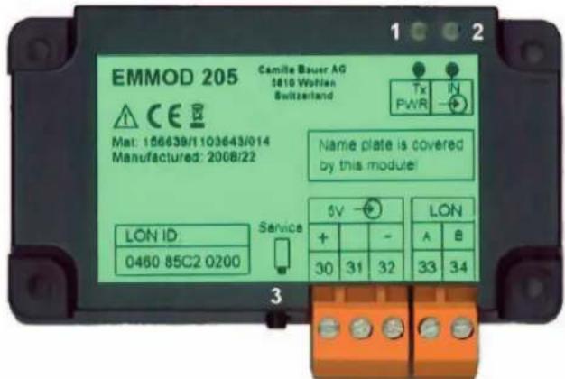
EMMOD 205 Camille Bauer AG 1 2 3610 Wohlen Switzerland Tx IN PWR Mat: 156639/1103643/014 Manufactured: 2008/22 Name plate is covered by this module! LON ID Service 0460 85C2 0200 5V LON + - A B 30 31 32 33 34 31 Tx / PWR - Communication LED with multiple functions
- Average brightness: Device is supplied with power.
- Short interruption: All necessary measurements have adopted by the basic unit. Grade for update rate.
- Always dark: Module or basic unit failure.
- Shortly very bright: The device is answering a request from the LON network. This way one may detect the external refreshing rate.
2 IN or OUT - State display
- Type A (Output): State display of alarm limit. The transistor output becomes active at the same time.
- Type E (Input): State of the connected contact. No display if the input in the A2xx is not configured.
3 Service key
If pressed the Neuron ID will be sent. The procedure is used when the device is integrated into the LON network.
8. Network variables and configuration parameters
Compatibility
The objects are oriented toward LON-Mark(R) guidelines. Due to the differing implementation in the basic unit A2xx these objects are not fully compatible. So e.g. the system and the transformer ratios can not be configured via bus. This can be done via the operating keys of the basic unit (A2xx) only.
Objects
The available variables are summarized in 4 groups which form an object (functional unit) each. The central object «nodeObject» serves to control the LON communication and to identify the device. The remaining objects (amMeter, powerMeter, voltMeter and energyMeter) contain the most important present values of the basic unit A2xx, but due to LON specific restrictions not all possible measurements. The allocation of the available variables to the measurements of the basic unit is given in the column A2xx in the tables.
Send condition
All variables of an object will be sent at the same time, as soon as one or more variables exceed the limit set (SendDelta) or if the set time (MaxSendTime) is reached.
Send condition of the variables of an object:
| maxSendTime | SendDelta | Transmission |
| 0.0 0.0 | None | |
| 0.0 >0.0 | As soon as | the increase or decrease of a value exceeds the amount set. |
| >0.0 | 0.0 | Cyclically, according to time set. |
| >0.0 | >0.0 | As soon as the increase or decrease of a value or the time set exceeds the amount defi ned. |
Network variables
The measured quantities available within the network, as well as status information and control commands from the EMMOD205, are defined as standard network variable types (SNVT). Conf i guration data specifi c to the network are defined as standard confi guration parameter types (SCPT).
All necessary information for network management tools is contained in the user files listed below which are available from the Camille Bauer Homepage (http://www.camillebauer.com).
The following functional profi les can be realized in accordance with LONMARK Draft V1.0 with the help of existing network variables:
• 3-phase voltmeter (2105)
• 3-phase ammeter (2104)
• 3-phase power meter (2103)
• 3-phase energy meter (2100)
Overview of versions
Standard version Type E (156 639)
| Recognition string(nvoOemType) | A2x0 EMMOD205 Vv.z |
| User fi les | EM205STD.APBEM205STD.XIF |
y.z - present version (e.g. 1.0)
Version for ECS-LAN Type A (156 647)
| Recognition string (nvoOemType) | A230sD0F0G1H1M1P0Q0U6V2W1Z0 |
| User fi les | EMU1387.APBEMU1387.XIF |
Description of variables for the standard version Type E (156 639)
Node - nodeObject (ObjectId = 0)
| Nv-Index Network variable Data type Description | |
| 0 nviRequest SNVT_obj_request Request for object state | |
| 1 nvoStatus SNVT_obj_status Output of object state | |
| 2 nvoOEMType SNVT_str_asc Device type | |
| 3 nvoFileDirectory SNVT_address Configuration fi le start address |
| Reference | Confi guration property | Data type Description | |
| Device | SCPTlocation | SCPTlocation(SNVT_str_asc) | Place of installation |
Current meter - amMeter (ObjectId = 1)
| Nv-Index | Network variable | Data type | Description | A2.. 2) |
| 4 | nvol1 | SNVT_amp_f | Current phase 1 | I1 |
| 5 | nvol3 | SNVT_amp_f | Current phase 3 | I3 |
| 6 | nvol2 | SNVT_amp_f | Current phase 2 | I2 |
| 7 | nvolAvg | SNVT_amp_f | Average of phase currents | IAvg |
| Reference | Configuration property | Data type | Description | Default |
| UCPTconnType | 1) | |||
| UCPTctCurrentPrim | 1) | |||
| UCPTctCurrentSec | 1) | |||
| Object | UCPTampSendDelta | UCPTampSendDelta | 4) | 0A |
| Object | SCPTmaxSendTime | SCPTmaxSendTime | 3) | 1s |
Power meter - powerMeter (ObjectId = 2)
| Nv-Index | Network variable | Data type | Description | A2.. 2) |
| 8 | nvoP | SNVT_power_f | Active power system | P |
| 9 | nvoP1 | SNVT_power_f Active power phase 1 P1 | ||
| 10 | nvoP2 | SNVT_power_f Active power phase 2 P2 | ||
| 11 | nvoP3 | SNVT_power_f Active power phase 3 P3 | ||
| 12 | nvoQ | SNVT_power_f | Reactive power system | Q |
| 13 | nvoPF | SNVT_pwr_fact | Power factor system 6) | PF |
| 14 | nvoPF1 | SNVT_pwr_fact | Power factor phase 1 6) | PF1 |
| 15 | nvoPF2 | SNVT_pwr_fact | Power factor phase 2 6) | PF2 |
| 16 | nvoPF3 | SNVT_pwr_fact | Power factor phase 3 6) | PF3 |
| 17 | nvoQ1 | SNVT_power_f | Reactive power phase 1 | Q1 |
| 18 | nvoQ2 | SNVT_power_f | Reactive power phase 2 | Q2 |
| 19 | nvoQ3 | SNVT_power_f | Reactive power phase 3 | Q3 |
| Reference | Configuration property | Data type | Description | Default |
| Object | SCPTmaxSendTime | SCPTmaxSendTime | 3) | 1.0s |
| Object | UCPTpwrSendDelta | UCPTpwrSendDelta | 4) | 0 W |
| Object | UCPTpwrFactSendDelta | UCPTpwrFactSendDelta | 4) | 0 |
Voltage meter - voltMeter (ObjectId = 3)
| Nv-Index N | Network variable Data type Description | A2.. | 2) | |
| 20 | nvoU12 | SNVT_volt_f | Voltage phase 1 to phase 2 | U12 |
| 21 | nvoU23 | SNVT_volt_f | Voltage phase 2 to phase 3 | U23 |
| 22 | nvoU31 | SNVT_volt_f | Voltage phase 3 to phase 1 | U31 |
| 23 | nvoU1 | SNVT_volt_f | Voltage phase 1 to neutral | U1 |
| 24 | nvoU2 | SNVT_volt_f | Voltage phase 2 to neutral | U2 |
| 25 | nvoU3 | SNVT_volt_f | Voltage phase 3 to neutral | U3 |
| 26 | nvoF | SNVT_freq_hz Frequency | F | |
| 27 | nvoUAvg SNVT_volt_f | Average of U1, U2, | U3 | 5) |
| Reference | Conf i guration property Data | type Description Default | ||
| UCPTconnType | 1) | |||
| UCPTptVoltagePrim | 1) | |||
| UCPTptVoltageSec | 1) | |||
| Object UCPTvoltSendDelta UCPTvoltSendDelta | 4) | 0 V | ||
| Object SCPTmaxSendTime SCPTmaxSendTime | 3) | 1.0s | ||
| Object UCPTfreqSendDelta UCPTfreqSendDelta | 4) | 0 Hz | ||
Energy meter - energyMeter (ObjectId = 4)
| Nv-Index Network variable Data type Description A2.. | 2) | |||
| 28 nviEnergyClr SNVT_switch | Reset of all meters | |||
| 29 nvoWhTpt | SNVT_e | ec_whr_f | 1) | |
| 30 nvoVarhTot | SNVT_e | ec_whr_f | 1) | |
| 31 nvoEnergyPwrPri | special | 1) | ||
| 32 nvoEPincLT | SNVT_reg_val | EPincLT | ||
| 33 nvoEPoutHT SNVT_reg_val | EPoutHT | |||
| 34 nvoEPoutLT | SNVT_reg_val | EPoutLT | ||
| 35 nvoEPincHT | SNVT_reg_val | EPincHT | ||
| 36 nvoEQindHT | SNVT_reg_val | EQindHT | ||
| Reference | Configuration property | Data type | Description | Default |
| UCPTenergyAccumMode | 1) | |||
| Object | SCPTmaxSendTime SCPTmaxSendTime | 3) | 1.0s | |
| Object | UCPTenergySendDelta | UCPTenergySendDelta | 4) | 0 Wh |
Description of variables for version ECS-LAN Type A (156 647)
Node - nodeObject (ObjectId = 0)
| Nv-Index | Network variable | Data type Description | |
| 0 | nviRequest | SNVT_obj_request | Request for object state |
| 1 | nviTimeSet | SNVT_time_stamp | 1) |
| 2 | nvoStatus | SNVT_obj_status | Output of object state |
| 3 | nvoFileDirectory | SNVT_address | Configuration file start address |
| 4 | nvoOemType | SNVT_str_asc | Device type |
| 5 | nvoSerialNumber | SNVT_str_asc | 1) |
| 6 | nvoPowerUpHours | SNVT_time_hour | 1) |
| Reference | Confi guration property | Data type Description | |
| SCPTmaxSndT | 1) | ||
| SCPTdevMajVer | 1) | ||
| SCPTdevMinVer | 1) | ||
| Device | SCPTlocation | SCPTlocation(SNVT_str_asc) | Place of installation |
Current meter - amMeter (ObjectId = 1)
| Nv-Index Network variable Data type Description A2.. | 2) | |||
| 7 | nvol1 | SNVT_amp_f | Current phase 1 | I1 |
| 8 | nvol3 | SNVT_amp_f | Current phase 3 | I3 |
| 9 | nvol2 | SNVT_amp_f | Current phase 2 | I2 |
| 10 | nvolAvg | SNVT_amp_f | Average of phase currents | IAvg |
| Reference | Configuration property | Data type | Description | Default |
| UCPTconnType | 1) | |||
| UCPTctCurrentPrim | 1) | |||
| UCPTctCurrentSec | 1) | |||
| Object | UCPTampSendDelta | UCPTampSendDelta | 4) | 0A |
| Object | SCPTmaxSendTime SCPTmax | SendTime | 3) | 1s |
Power meter - powerMeter (ObjectId = 2)
| Nv-Index Network variable Data type Description A2.. | 2) | ||
| 11 nvoWatTot SNVT_power_f Active power system P1+P2+P3 | |||
| 12 nvoWat1 SNVT_power_f Active power phase 1 P1 | |||
| 13 nvoWat2 SNVT_power_f Active power phase 2 P2 | |||
| 14 nvoWat3 SNVT_power_f Active power phase 3 P3 | |||
| 15 nvoVarTot SNVT_power_f Reactive power system Q | |||
| 16 nvoPwrFactrTot SNVT_pwr_fact Power factor system | 6) | PF | |
| 17 nvoPwrFactr1 | SNVT_pwr_fact Power factor phase 1 | 6) | PF1 |
| 18 nvoPwrFactr2 | SNVT_pwr_fact Power factor phase 2 | 6) | PF2 |
| 19 nvoPwrFactr3 | SNVT_pwr_fact Power factor phase 3 | 6) | PF3 |
| Reference | Configuration property | Data type | Description | Default |
| Object | SCPTmaxSendTime | SCPTmaxSendTime | 3) | 0.8s |
| Object | UCPTpwrSendDelta | UCPTpwrSendDelta | 4) | 0 W |
| Object | UCPTpwrFactSendDelta | UCPTpwrFactSendDelta | 4) | 0 |
Voltage meter - voltMeter (ObjectId = 3)
| Nv-Index | Network variable | Data type | Description | A2.. 2) |
| 20 | nvoU12 | SNVT_volt_f | Voltage phase 1 to phase 2 | U12 |
| 21 | nvoU23 | SNVT_volt_f | Voltage phase 2 to phase 3 | U23 |
| 22 | nvoU31 | SNVT_volt_f | Voltage phase 3 to phase 1 | U31 |
| 23 | nvoU1N | SNVT_volt_f | Voltage phase 1 to neutral | U1 |
| 24 | nvoU2N | SNVT_volt_f | Voltage phase 2 to neutral | U2 |
| 25 | nvoU3N | SNVT_volt_f | Voltage phase 3 to neutral | U3 |
| 26 | nvoFreq | SNVT_freq_hz | Frequency | F |
| 27 | nvoUAvg | SNVT_volt_f | Average of U1, U2, U3 | 5) |
| Reference | Configuration property | Data type | Description | Default |
| UCPTconnType | 1) | |||
| UCPTptVoltagePrim | 1) | |||
| UCPTptVoltageSec | 1) | |||
| Object | UCPTvoltSendDelta | UCPTvoltSendDelta | 4) | 0 V |
| Object | SCPTmaxSendTime | SCPTmaxSendTime | 3) | 1.0s |
| Object | UCPTfreqSendDelta | UCPTfreqSendDelta | 4) | 0 Hz |
Energy meter - energyMeter (ObjectId = 4)
| Nv-Index | Network variable | Data type | Description | A2.. 2) |
| 28 | nviEnergyClr | SNVT_switch | Reset of all meters | |
| 29 | nviEnergyFreeze | SNVT_switch | 1) | |
| 30 | nvoWhTot SNVT_elec_whr_f | 1) | ||
| 31 | nvoVarhTot | SNVT_elec_whr_f | 1) | |
| 32 | nvoEnergyClrTs | SNVT_time_stamp | 1) | |
| 33 | nvoEnergyFlowHrs | SNVT_time_hour | 1) | |
| 34 | nvoEnergyPwrPri | UNVT_energyPower | Energy, Total power,Failure state 7) | EPincHT(P1+P2+P3) |
| 35 | nvoEnergyPwrSec | UNVT_energyPower | 1) | |
| 36 | nvoRegValWhFr | SNVT_reg_val_ts | 1) | |
| 37 | nvoRegValWhSec | SNVT_reg_val | 1) | |
| 38 | nvoRegValWhTot | SNVT_reg_val | Active energy demand high tariff | EPincHT |
| 39 | nvoRegValVarhTot | SNVT_reg_val | Reactive energy demand hightariff | EQindHT |
| 40 | nvoEnergyPwrVarh | UNVT_energyPower | 1) |
| Reference | Configuration property | Data type | Description | Default |
| UCPTenergyAccumMode | 1) | |||
| Objekt | SCPTmaxSendTime | SCPTmaxSendTime | 3) | 1.0s |
| Objekt | UCPTenergySendDelta | UCPTenergySendDelta | 4) | 0 Wh |
| UCPTpulseRate | 1) |
Remarks:
1) These variables are only placeholders and not available in this version. The configuration of system and transformer ratios must be done via the keys of the basic device.
2) Depending in the system some measurands are not available (see basic unit A2xx). In this case the value 8.888e+030 will be output resp. 1.55555 for power factors, to allow clear recognition of this circumstance.
3) Here the interval time for the sending of all variables of the appropriate object (function block) can be set. If this time is set to 0.0s the time monitoring is switched off.
4) Here the maximum absolute alteration of the variable value since the last transmission can be set. If the value is exceeded all values of the object are sent again. If the value is set to 0.0 no transmission will take place.
5) These value is calculated locally and is not available in the basic unit A210/A220. Uavg=(U1+U2+U3)/3.
6) If the power factor can't be calculated due to low input signals the value 1.1111 is output.
7) Special variable for summation station U1601.
9. Programming of digital input/output
There are detailed programming instructions in the operating instructions for the basic instrument A2xx.
Programming of digital output (Type A)
The switching state follows the state of digital output 1 of the basic unit. The selection of the measurand to monitor at the limit are set in the basic unit (OUT1). Remark: The output of energy pulses is not possible.
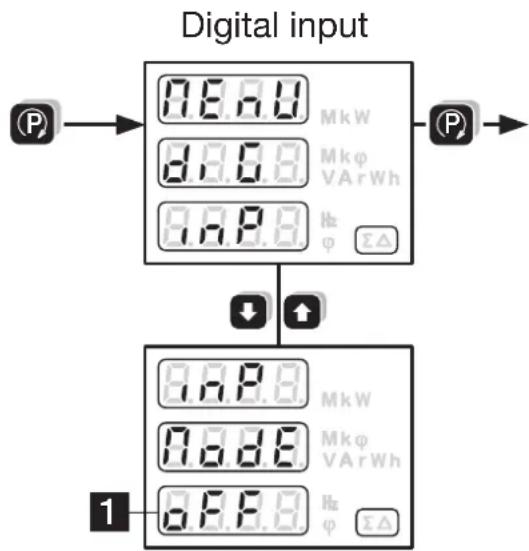
Programming of digital input (Type E)
Brief instructions
Press P > 2 sec.
Press the Ⓐ button, until the menu required, "Digital input" appears. Enter the parameter level with the ↓ button.
Press the Ⓗ button and change the flashing parameter with the ↓ buttons.
Press P > 2 sec. The basic instrument is now in display mode again.
The module must be plugged in for programming.
flowchart
graph TD
    A["Input"] --> B["Digital Input"]
    B --> C["Output 1"]
    B --> D["Output 2"]
    style A fill:#f9f,stroke:#333
    style B fill:#ccf,stroke:#333
| No. | Undetopust displayMiddle display | (Selection, * = default) | Meaning Hints | |
| 1 | 8.8.8.7.8.8. | Operating mode of the digital input on the interface module | (input mode) | |
| 8.8.8.* | Input inactive | |||
| H.E.E. | Input used for high/low tariff switching of meters | |||
| 5.9.0. | Input used for power interval synchronization | The time interval in the “Synctime” menu is ignored |
10. Declaration of conformity

EG - KONFORMITÄTSERKLÄRUNG EC DECLARATION OF CONFORMITY

CAMILLE BAUER
Dokument-Nr./
EMMOD205_CE-konf.DOC
Document.No.:
Hersteller/ Camille Bauer AG
Manufacturer: Switzerland
Address: CH-5610 Wohlen
The above mentioned product has been manufactured according to the regulations of the following European directives proven through compliance with the following standards:
Leiter Technik / Head of engineering Qualitätsmanager / Quality manager
