
HW-800 - Garage door Tormatic - Free user manual and instructions
Find the device manual for free HW-800 Tormatic in PDF.

User questions about HW-800 Tormatic
0 question about this device. Answer the ones you know or ask your own.
Ask a new question about this device
Download the instructions for your Garage door in PDF format for free! Find your manual HW-800 - Tormatic and take your electronic device back in hand. On this page are published all the documents necessary for the use of your device. HW-800 by Tormatic.
USER MANUAL HW-800 Tormatic
natural_image
3D rendering of a white air conditioner unit with black handle and ventilation grille (no text or symbols visible)W-800
WN 929002-63-6-50 07/2017
GB Copyright and disclaimer
© 2017 TORMATIC®
No part of this document may be reproduced, distributed, or transmitted in any form or by any means, electronically or mechanically, including photocopying and recording for any purpose, without the express written authorization of TORMATIC.
text_image
Technical diagram of a structural assembly with numbered components and an inset showing a cable connection detail.text_image
Technical diagram of a mechanical assembly with numbered components and safety warning symbolstext_image
Technical diagram showing three labeled mechanical components (I, II, III) with directional arrows indicating movement or force.text_image
I H G F E Y
text_image
I H G F E 180R3. Eingang STOP A
text_image
I H G F E4. Eingang STOP B
text_image
I H G F E REL LS LS + - +text_image
I H G F E LS2 1 2 LS2 1 2text_image
I H G F E 24V-6. Spannungsversorgung 24 V DC, max. 100 mA (permanent)
text_image
Image showing a parking tag icon with 'P' and placeholder text, likely indicating parking or parking-related items.natural_image
Illustration of a finger pressing down on a padlock and three triangular buttons (no text or symbols)Menü 3 + Menü 4:
flowchart
graph TD
    A["Device 1"] --> B["Triangle"]
    C["Device 2"] --> D["Down Triangle"]
    B --> E["D"]
    D --> E
    E --> F["Striped Panel with Arrow"]
flowchart
graph TD
    A["8"] --> B["△"]
    C["△"] --> D["○"]
    B --> D
    D --> E["↓"]
Kraftlernfahrt

Warnung:
text_image
F < 400N 50mmnatural_image
Illustration of a hand pressing a small rectangular object on a circular surface (no text or symbols)Zyklenzähler
Contents and intended audience....30
Language....30
Symbols used in this manual 30
Use according to purpose 30
Safety 31
General safety precautions 31
Specific safety precautions....31
Product description....32
General product overview 32
Control elements....32
Functioning of integrated safety unit....33
Installation....33
Safety instructions for installation....33
TTZ Directive - Burglar resistance for garage doors 33
Scope of delivery....34
Prepare the site for installation....34
Mount the garage door operator....35
Connect the garage door operator to electrical power and controls....36
Program the drive head....38
Special settings....42
Complete the installation procedure 46
Operation 46
Safety instructions for operation....46
Open or close the garage door (in normal operation mode) 46
Manually open or close the garage door 46
Open or close the garage door (other operation modes)....47
Diagnostic display 48
Restore the factory settings....49
Cycle counter 49
Technical data....50
Disposal....50
Inspection and test log book for the door system....51
Testing of the garage door operator....51
Term of the Guarantee 53
Maintenance / Checks 53
Cleaning / Care 53
Declaration of conformity and Installation....54
About this manual
Contents and intended audience
This manual gives information about the W-800 series garage door operator (hereinafter referred to as ‘the product’). The manual is intended for technicians that install and maintain the product, and for consumers that use the product on a daily base.
Language
This manual was prepared in German. Any other language version is a translation of this original.
Symbols used in this manual

Warning:
This indicates a possibly dangerous situation that might lead to serious injury.

Warning high voltage:
This indicates work steps that may be carried out only by a trained and skilled electrician.

Caution:
This indicates a possibly dangerous situation that might lead to material damage to the product.
Use according to purpose
The product is designed exclusively for opening and closing spring or weight-balanced garage doors. It may not be used for garage doors without spring or weight-balancing mechanisms. See CE declaration.
Safety
General safety precautions

Warnung:
Make sure that you read this manual and that you understand its contents before you start working with the product.

Warnung:
Keep this manual with the product for future reference.
- Obey the instructions in this manual. Incorrect installation or incorrect use can cause serious injury or damage to the product.
- Any damage or injury as a result of not following the instructions in this manual will render the manufacturer's liability null and void.
- Only use the product for the intended use as mentioned in this manual. See CE declaration.
- Please also see the safety instructions for operation (see Operation, Page 46).
- Installation must only be carried out about by qualified technicians.
Specific safety precautions
- The product runs on high voltage. Before you start work on electrical systems, do the following:
- Make sure that the product is disconnected from the electrical power supply.
- Make sure that the power cannot be reconnected unintendedly during work on the electrical system.
- Never make any modifications or changes to the product that have not been expressly approved by the manufacturer.
- The design and execution of the product based on this corresponds to state-of-the-art technology.
- Only use genuine spare parts of the manufacturer. Wrong or faulty spare parts can cause damage, malfunctions or even a total failure of the product.
Product description
General product overview
text_image
Technical diagram of a cable or electrical connector assembly with numbered components and an inset showing connection details.* Example garage door illustration
- Drive head including LED module 11. Door connector attachment
- Rail (model example) drive side 12. Linking bar
- Carriage 13. Central support
- Rail connector (model example) 16. Support straps drive head
- Rail (model example) door side 16. Support straps track
- Tensioner 17. Mains cable, 1.2 m
- Wall bracket 20. Telescopic fitting for sectional doors (accessory)
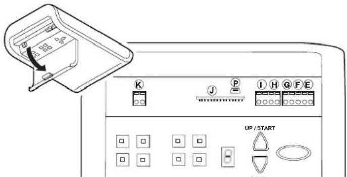
Control elements
text_image
1 A B C D A1 15A. Numerical display (A1 digital point)
C. OPEN / Start button
B. CLOSE button
D. Program button (PROG button)
- Drive head
- Hand transmitter
Functioning of integrated safety unit
If the closing garage door encounters an obstruction, the closing motion stops and the door opens a few centimetres again, or, depending on its position, completely.
If the opening garage door encounters an obstruction, the door stops and moves back for approximately 1 second.
Installation
Drive and accessories

text_image
2x AWG 22 max.1800 mm 2 x 2x AWG 22 Y-OB 2 x 1,0 2x AWG 22 2x AWG 22 mm 005Safety instructions for installation
• Installation must only be carried out about by qualified technicians.
- Read these installation instructions before you start installing the product.
TTZ Directive - Burglar resistance for garage doors
In order to comply with the TTZ guideline, corresponding accessories are necessary for increased burglar protection. These accessories can be ordered separately. Please use our Secü Kit and follow the instructions WN 020690-45-5-32. Also follow the instructions WN 902004-21-6-50 as installation instructions for TTZ guideline burglary resistance for garage doors.
Scope of delivery
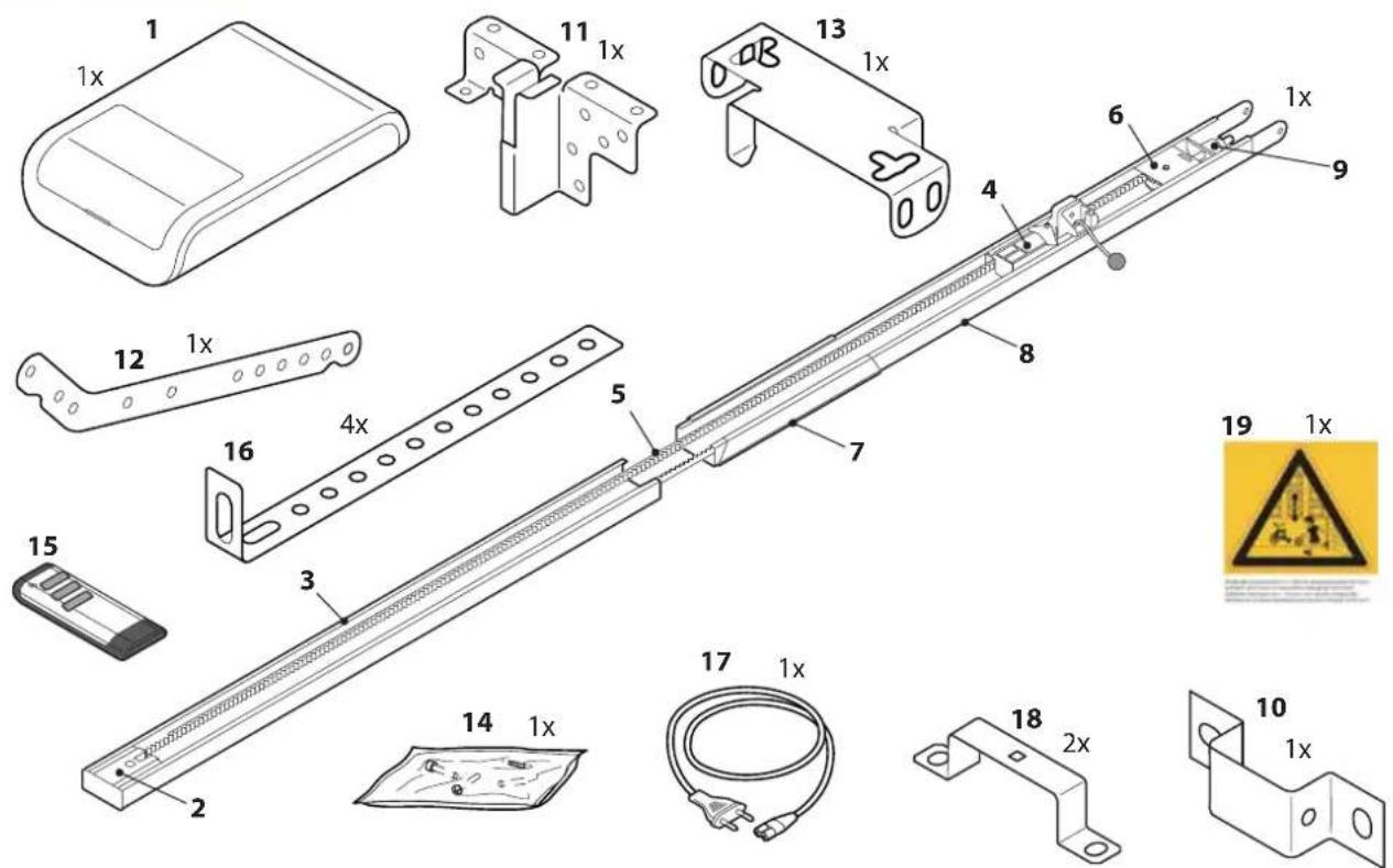
text_image
Technical diagram of a mechanical assembly with numbered components and safety warning symbols- Drive head including LED module
- Pinion*
- Rail (model example) drive side*
- Carriage*
- Toothed belt or chain*
- Deflection roller*
- Rail connector (model example)*
- Rail (model example) door side*
- Tensioner*
-
Wall bracket*
-
Door connector attachment
- Linking bar
- Central support
- Bag of screws
- Hand transmitter*
- Ceiling mounting
- Mains cable, 1.2 m length
- Mounting bracket
- Warning label
*Optional
Attention: Check the supplied screws and wall plugs to make sure that they are suitable for the structural condition on the installation site.
Prepare the site for installation
- The maximal distance between the drive head and wall socket is 1.2 m.
- Check the stability of the garage door. If necessary, tighten the screws and nuts of the garage door.
- Make sure that the garage door runs smoothly.
- Lubricate shafts and bearings.
- Check the pretension of the springs and adjust if necessary.
- Establish the clearance at opening and closing of the garage door (h).
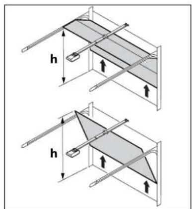
text_image
h h- Close the garage door and disable any existing locks. Dismantle the locks if necessary.

Warning:
Some parts of the latching devices on the existing garage door can form pinch or shear points. If necessary, remove hazardous parts before installation.
- For garages without a second entrance, an emergency release is required (accessory).
- If the garage door is a wicket/pass door, install the wicket door contact first.

Warning:
Do not allow parts of the gate to enter public footpaths or roads.
Mount the garage door operator
Follow instructions as shown in the A3 Instruction poster.
| Step Installation | |
| 1 Fold | out the track to its full length (3&8).Push the track connector (7) centrally over the joints. The chain or the toothed belt may have to be re-stressed. See illustration. |
| 2 Mount | the center suspension (13) to the guide rail.Mount the mounting brackets (18) on the drive head (1). |
| 3 Mount | the connector attachment (11) to the garage door. |
| 4 Mount | the wall bracket (10). |
| 5a5c/d | Mount the guide rail (3&8) to the wall bracket (10).Mount the ceiling mountings (16) to the center bracket (13) and to the drive head (1).Then, mount the ceiling mountings (16) to the ceiling. |
| 6 Connect | the linking bar (12) between the carriage (4) and the garage door connector attachment (11). |
| 7 For programming, open the cover of the drive head with a screwdriver or a similar tool. | |
| 8 Attach | the warning sticker (19) to the inside of the garage door so that it is easily visible. |
Disengage the carriage
During the proceeding work, it may be necessary to disengage the carriage from the connector attachment. This can be done without the need to disconnect the linking bar.
- To move the garage door, manually pull on the pull cord (l) on the carriage.
- Disconnect the carriage from the toothed belt or the chain.
- The garage door can now be moved manually.
- To operate the gate manually for a longer period of time, you can insert the locking pin (II) into the carriage (III) in the bore provided for this purpose. To restore normal operation, loosen the locking pin (II).
text_image
II III IConnect the garage door operator to electrical power and controls

Warning high voltage:
- Pull out the main plug from the mains socket before you open the cover of the drive head.
- Do not connect any live leads. Only connect potential-free buttons and potential-free relay outputs.
• After connecting all cables, connect the cover to the drive head again.

Warning:
Before using the operator for the first time, it must be tested to make sure that it is working properly and safely (see section on Maintenance/Checks).

Warning:
Danger by optical radiation!
If you look at an LED for an extended period from a short distance, this can cause optical binding. Sight is then severely restricted for a short time. This can result in serious or fatal injuries.
You must not look directly at an LED.
text_image
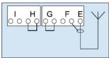
UP / START1. External antenna
Lead the antenna upward through the housing recess.
When using an external antenna, the shield must be placed on the right adjacent terminal (F).
E - Connector for antenna
2. External pulse generator
F - Connector for external impulse generator (accessories, e.g. keyswitch or code keypad)
text_image
I H G F E Y
text_image
I H G F E 180R3. Input STOP A
The drive is stopped or the start-up is suppressed via this input.
G - Connection for slip contact (accessory) or emergency stop.
text_image
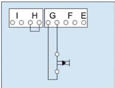
I H G F E4. Input STOP B
This input activates the automatic reversal of the drive during closing.
H - Connection 4-wire photoelectric sensor (e.g. LS5)
text_image
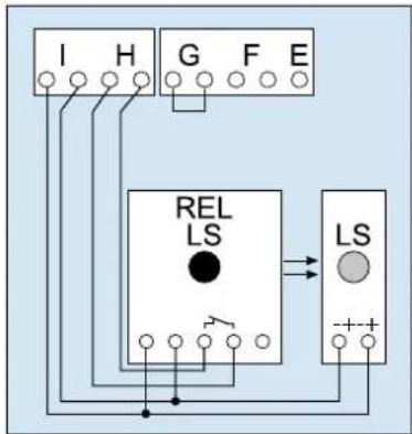
I H G F E REL LS LS + - +G // H - Connection of photoelectric sensor LS2 (please refer to the connection points of the photoelectric sensor manual for use of other photoelectric sensors)

text_image
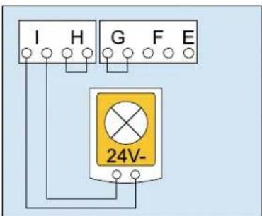
I H G F E LS2 1 2 LS2 1 25. Power supply 24 V DC, max. 100 mA (switched)
I - Connection for e.g. 24V signal light (accessory)
text_image
I H G F E 24V-6. Power supply 24 V DC, max. 100 mA (permanent)
I - Connection for e.g. external receiver (accessory)
text_image
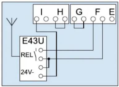
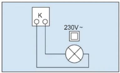
I H G F E E43U REL 24V-7. Lighting
K - Connection for external, protectively insulated lighting or signaling lamp (protection class II, max 500W) (accessory)

Caution!
Do not connect a push button.
text_image
K 230V~8. smartGarage
P - Connection for Mobility Module (accessory)

text_image
Diagram showing a parking tag icon with 'P' label and placeholder textPulse generator and external safety devices

In situations of increased requirements in terms of personal protection, we recommend, in addition to the internal power limitation of the drive, the installation of a photoelectric sensor. Further information on our range of accessories can be found in our sales literature. Consult your specialist dealer.
Warning label
Place the sticker clearly visible on the inner surface of the garage door.
Dismantling the operator
- Pull out the mains plug and disconnect all existing terminals.
- Disconnect garage door and operator. Fix garage door.
- Proceed according to the Installation instruction poster, but in reverse sequence.
Program the drive head
This section describes the normal programming of the drive head during installation.
For further adjustments, or for special adjustments, refer to the section 'Special settings'.
Preparation
- Make sure that the garage door is securely engaged in the carriage.
- Make sure that the aerial is correctly positioned.
- Make sure that you have all hand transmitters for this garage door at hand.
- Open the cover of the drive head with a screwdriver.
- Connect the mains plug to the mains socket. The point display lights up.
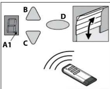
Menu 1:
Program the start signal of the hand transmitter
- Briefly press the programming button (PROG button) (D). The display shows "1".
- When the display flashes, press the hand transmitter button with which you will later start the drive until the digital point (A1) on the display blinks 4 times.
- As soon as the light goes out, you can set the next hand transmitter (see Step 1).
Note: Up to 30 codes can be learned.
text_image
A1 B C DMenu 2:
Programming the 4-minute light
- Briefly press the programming button (PROG button) (D) twice. The display shows "2".
- Press the button on the hand-held transmitter to control the light until the digital point (A1) flashes 4 x.
As soon as the light goes out, you can set the next hand transmitter (see Step 1).
Note: Programming the ventilation position and partial opening: see menu 9.
Note: Up to 30 codes can be learned. (Example 15x start 15x light).
text_image
A1 B C DDelete all radio codes
- Pull the main plug
- Push and hold the oval PROG-Button (D).
- Connect the mains plug to the mains socket and keep the PROG button (D) pressed until the digital point flashes quickly.
natural_image
Illustration of a finger pressing down on a padlock and three triangular buttons (no text or symbols)Menu 3 + Menu 4:
Setting the end positions
- Keep the programming button (PROG button) (D) pressed in for approximately 3 seconds. The display shows "3".
- Press the OPEN button (B) and check if the garage door moves to the OPEN position.
- If the garage door moves in the wrong direction, keep the programming button (PROG button) (D) pressed in for approximately 5 seconds until a chaser light appears.
- Keep the OPEN button pressed until the garage door is at the desired end position OPEN. If needed, press the CLOSE button (C) to adjust the position.
- Once the garage door is at the desired OPEN position, press the programming button (PROG button) (D). The display shows "4".
- Press the CLOSE button (C) as soon as the display flashes.
- Keep the CLOSE button pressed until the garage door is at the desired end position CLOSE. If needed, press the OPEN button (A) to adjust the position.
- Once the garage door is at the desired end position CLOSE, press the programming button (PROG button) (D). The display shows "0".
- Continue with the force learning cycle.
text_image
B C D
text_image
B C DForce learning cycle

Warning:
During this procedure, the operator automatically learns the normal mechanical force required to open and close the garage door. Force limits are deactivated until the conclusion of the learning cycle. Keep a sufficient distance from the entire path of motion of the garage door!
Do not interrupt this procedure.
Note:
During this procedure the display shows a "0".
- Press the OPEN button (B) or use the set hand transmitter. The garage door moves from the end position CLOSE and moves to the end position OPEN.
- Press the OPEN button (B) again or use the set hand transmitter. The garage door moves from the end position OPEN to the end position CLOSE.
After about 2 seconds, the '0' on the display goes out.
Note: After completing the force learning cycle, the display '0' must go out.
flowchart
graph TD
    A["Component B"] --> B["Component C"]
    B --> C["Component D"]
    C --> D["Downward Arrow"]
Checking force limit
- Place an force gauge or obstruction (e.g. the operator's cardboard box) in the closing area of the door.
- Close the garage door. The garage door moves to the end position CLOSE. When the garage door reaches the obstruction, the garage door must stop and then move back to the end position OPEN.
- If the door can lift persons (e.g. openings greater than 50 mm or treads), the force limiting unit must be checked in the opening direction: For additional load of the door with 20 kg of mass, the drive has to stop.
text_image
F< 400N 50mmDelete force learning cycle
Note: The force learning cycle always starts from the end position CLOSE.
The force learning cycle must be repeated after each replacement of the garage door springs:
Proceed to Menu 5 (see special settings) and keep the programming button (PROG button) (D) pressed for 3 seconds. The display shows "0". Complete the process as described in the force learning cycle section on page page 40.

For your safety, we recommend that the door system be checked before initial use and as needed - but at least once a month - by a specialist. We recommend consulting a specialist company.
Special settings
Open the special settings menu
- Keep the programming button (PROG button) (D) pressed in for approximately 3 seconds. The display shows "3".
- Press the programming button (PROG button) (D) again. The display shows "4".
- Keep the programming button (PROG button) (D) pressed in again for approximately 3 seconds. The display shows "5".
Menu 5 + Menu 6:
Force limitation for Open and Close.

Warning:
If the setting is too high, persons may be placed at risk of injury. In the delivery state, the set value is '6' when opening and '4' when closing. We recommend selecting the appropriate door type in menu 8 before the force learning cycle.
- Select menu item "5".
After about 2 seconds, the display blinks and the set value of the power limit for upward motion appears. -
If desired, adjust the setting with the aid of the OPEN (B) and CLOSE (C) buttons.
-
Press the programming button (PROG button) (D).
The display shows "6". After about 2 seconds the display and the set value for the power limit for closure appears.
- If desired, adjust the setting with the aid of the OPEN (B) and CLOSE (C) buttons.

Warning:
The force on the main closure side must not exceed 400 N / 750 ms!
- Press the programming button (PROG button) (D). The display shows "7".
Menu 7:
Adjust the light phases
-
Select menu item "7".
After about 2 seconds the display blinks and the set value for light time appears.
The factory setting is "0". -
If desired, adjust the setting with the aid of the OPEN (B) and CLOSE (C) buttons.
| Menu value Light time Warning time 24 V | ||
| 0 60 s 0 s 60 s | ||
| 1 120 s 0 s 120 s | ||
| 2 240 s 0 s 240 s | ||
| 3 0 s 0 s 0 s | ||
| 4 0 s 3 s 0 s | ||
| 5 60 s 3 s 0 s | ||
| 6 120 s 3 s 0 s | ||
| 7 60 s 0 s TAM | ||
| 8 120 s 0 s TAM | ||
| 9 240 s 0 s TAM | ||
| Remarks:- TAM (Door open message): 24 volts at door not closed.- With set warning time light and 24V for drive of control goes on. | ||
- Press the programming button (PROG button) (D).
The display shows "8".
Menu 8:
Door adjustments
- Select menu item "8".
After about 2 seconds the display blinks and the set value time appears.
At delivery, the factory setting is '4'.
For optimal movement and to maintain the forces, the corresponding door type must be selected.
- If desired, adjust the setting with the aid of the OPEN (B) and CLOSE (C) buttons.
| Menu value Door type |
| 0 Double swing gate |
| 1 Non-swinging door, Canopy |
| 2 Swing door, Kipptor normal |
| 3 Swing door, tilt sensitive running |
| 4 Universal setting (factory) |
| 5 Sectional door with tension spring fitting (Topspeed) |
| 6 Sectional door with torsion spring fitting (Topspeed) |
| 7 Industrial door with standard fittings |
| 8 Side section door (Topspeed) |
| 9 Side section door with secondary closing edge |
- Press the SAVE button (D).
The display shows "9".
Menu 9:
Adjustment other operating modes
- Select menu item "9".
After approximately 2 seconds, the display flashes and shows the set value of the operating mode. The factory setting is "0"
- If desired, adjust the setting with the aid of the OPEN (B) and CLOSE (C) buttons.
| Menu value | Description Remarks | |
| 0 Normal | operation Factory settings | |
| 1 Normal | operation with ventilation settings* | Allows the ventilation of the garage. In this mode, the garage door is approximately 10 cm wide open. To start up the ventilation setting, press the second button on the hand transmitter or use a DuoControl/Signal 111 (accessories) setting* that must be programmed in Menu 2.The garage door can be closed at any time using the hand transmitter.The garage door closes automatically after 60 minutes. |
| 2 Partial | opening of side sectional door* | In this mode, the garage door is approximately 1 m wide open. To start up the partial opening, press the second button on the hand transmitter or use a button of DuoControl/Signal 111 (accessories)* that must be programmed in Menu 2. |
| 5 OPEN | CLOSE operation | After pulsing in CLOSE position, the drive starts and the door moves into end position OPEN. Another impulse entry during drive has no effect and the door continues to open. After impulse entry in OPEN position, the door closes. On impulse entry during closing, the door stops and starts again. |
| 6 Automatic closing ('AR')** | Impulse always causes an opening of the door. After the hold-open time and warning time (setup menu A) the door closes automatically.An interruption of the photoelectric sensor during closing causes stop and reverse direction. Interruption during opening drive has no effect. | |
| 7 Automatic closing ('AR')** | Function as in point 6, however, an interruption of the photoelectric sensor during open time causes early termination of open time and the warning time starts. | |
| 8 Automatic closing ('AR')** | Function as in point 7, however, an impulse during open time causes early termination of open time and the warning time starts. | |
| 9 Automatic closing ('AR')** | Same function as 8, but without early warning phase. | |
| Remarks:- *: The second button of the transmitter must be reset after changes in operating modes 1 or 2.- **: A photoelectric sensor must be installed. | ||
- Press the programming button (PROG button) (D).
In setting 0, 1, 2 and 5 value "0" is displayed. End of menu (if necessary, continue with power learning cycle). In setting 6, 7, 8 and 9 value "A" is displayed. Continue with menu "A"

Warning:
Automatic door - Do not stop in the movement area of the door, because it may start unexpectedly!
Menu A:
Set open time
Only in conjunction with function 'Automatic close'.
- Select menu item "A".
After approximately 2 seconds, the display flashes and shows the set value of the operating mode.
- If desired, adjust the setting with the aid of the OPEN (B) and CLOSE (C) buttons.
| Menu value | Open time (without warning time 10 seconds) |
| 0 0 s | |
| 1 10 s | |
| 2 30 s | |
| 3 60 s | |
| 4 90 s | |
| 5 120 s | |
| 6 150 s | |
| 7 180 s | |
| 8 210 s | |
| 9 240 s |
- Press the programming button (PROG button) (D).
The display shows "0".
- Proceed with the force learning cycle.
Complete the installation procedure
- Close the cover of the drive head.
- Check if the garage door operates properly and safely. Refer to the section 'Maintenance / Checks'.
Operation
Safety instructions for operation

Warning:
Use only by trained persons. All users must be familiar with the applicable safety regulations.

Warning:
Keep the hand transmitters out of reach of children.

Warning:
When the drive is actuated, the opening and closing processes must be monitored.
The garage door must be visible from the place of operation.
Make sure that no persons or objects are in the travel path of the garage door.
The stated safety and instructions as well as the accident prevention regulations and general safety regulations must be adhered to.
Open or close the garage door (in normal operation mode)
The garage door can be operated by many devices (hand transmitter, key switch etc.). This description only mentions the hand transmitter. But the other devices work in the same way.
- Briefly press the button on the hand transmitter.
Depending on the current position, the garage door then goes to the OPEN or CLOSE position. - If needed, briefly press the button on the hand transmitter to stop the movement of the garage door.
- If needed, press the button on the hand transmitter once again to make the garage door move in the other direction.
Note:
A button on the hand transmitter can be set with the function "4-minute light". By using the hand transmitter the light will be turned on, independently from the drive unit. After 4 minutes the light will be turned off.
Manually open or close the garage door
During adjustments to the garage door, or during power failure, the garage door can be manually opened or closed.
- To move the garage door, manually pull on the pull cord (I) on the carriage.
- Disconnect the carriage from the toothed belt or the chain.
- The garage door can now be moved manually.
- To operate the gate manually for a longer period of time, you can insert the locking pin (II) into the carriage (III) in the bore provided for this purpose. To restore normal operation, loosen the locking pin (II).

text_image
II III I
Warning:
By using the quick release uncontrolled movements of the garage door are possible.
The garage door may be out of balance or the springs might be broken or worn. Please consult your dealer of manufacturer.
Note: When installing the system, locking elements of the garage door operator are dismantled. These should be reinstalled if the garage door has to be controlled manually over a longer period of time. This way the garage door can be locked when closed.
Open or close the garage door (other operation modes)
- Possible operating modes see section "Special settings".
Diagnostic display
| Number | State Diagnosis / Remedy | |
| 8 | The operator starts up and “0” goes out. | In normal operation, drive receives start signal via START input or by drive unit. |
| 8 | Garage door has reached end position OPEN. | |
| 8 | Garage door has reached end position CLOSE. | |
| 8 | End position has not been reached. | |
| 8 | The display shows a “0” during the next opening and closing cycle and then goes out. | The operator is carrying out a learning cycle for the force limit.Caution: During this travel cycle the operator does not monitor the force. Make sure that no persons or objects are in the travel path of the garage door. |
| 8 | The display continues to show a “0”. | The force-learning cycle did not complete and must be repeated.The door’s end-of-travel position may have too much pressure.Set the door’s pressure to the correct level. |
| 8 | The door does not open or close. | Interruption at STOP A or activation of an external safety device (such as a pass-door). |
| 8 | The door does not close. Interruption at STOP B or activation of an external safety device (such as a photoelectric sensor). | |
| 8 | The door setting and learning cycle did not complete correctly. | You must use menu stages 3 and 4 to complete the door settings correctly and then complete the force-learning cycle. |
| 8 | There is a permanent impulse signal at the start input. | Start signal is not detected or pulse duration (eg button jammed). |
| 8 | An error occurred in setting the operator. | The travel path is too long.Repeat setting procedure with menu stages 3 and 4. |
| 8 | Error in learning cycle. Repeat position learning cycle with menu stages 3 and 4.Reduce force when approaching the end-of travel positions. | |
| 8 | The door does not open or close. An error occurred during the self-test. Disconnect the power supply. | |
| 8 | Motor standstill. The motor does not rotate. Call a specialist company to repair the motor. | |
| 8 | Electronic brake activated. The garage light remains on. | The operator is pulled from upper end position. Check the door and the springs. Setting upper end lower. |
| 8 | The vacation lock is activated.The door does not open. | The side switch for SafeControl/Signal 112 is active. A reset is required. |
Restore the factory settings
- Press the OPEN and CLOSE buttons at the same time.
- Press the buttons for approximately 3 seconds after you put the power plug into the electrical socket.
natural_image
Illustration of a hand holding a small rectangular object with a grid pattern, no text or symbols presentCycle counter
The cycle counter stores the number of OPEN/CLOSE actions powered by the drive.
To read the meter, hold the button in for 3 seconds until you see a number. The digital display shows the numbers starting from the highest to the lowest decimal place consecutively. At the end, a horizontal line appears on the display, for example: 3456 movements, 3456 -
Technical data
The drives of the W-800 series are suitable for the following doors:
Door type: Canopy/non-swinging doors, double wing doors, swing doors/tilting doors, sectional doors/side section doors
Model Specifications
Operator type: W-800
Rated load capacity: 240 N
Power rating max: 800 N
Connection values: 230 V / 50 Hz
Power input:
Standby: <0.5 W
Max. operation: 240 W
Cycles: 3/h
Lighting LED: 1.6 W
Safety according to EN13849-1:
Input STOP A: Cat. 2 / PLC
Input STOP B: Cat. 2 / PLC internal force limit: Cat. 2 / PLC
text_image
+ 60°CTemperature range: - 20°C
Protection class: IP20, only for dry rooms
Volume: ≤ 70 dB (A)
Manufacturer: TORMATIC
Eisenhüttenweg 6
44145 Dortmund
Germany
www.tormatic.de
Disposal

Dispose of the product according to the laws and regulations of the respective country of use.
Inspection and test log book for the door system
Owner / operator ____
Location of door system: ____
Operator data
Operator type: ____ Manufacture date: ____
Manufacturer: ____ Operating mode: ____
Door data
Type: ____ Year of construction: ____
Serial no.: ____ Door leaf weight: ____
Door dimensions: ____
Installation and initial operation
Company, installer: ____ Name, installer: ____
Initial operation on: ____ Signature: ____
Miscellaneous Changes
Testing of the garage door operator
Caution:
An inspection is not the same as maintenance! After an inspection, the user must do any necessary maintenance.
Drive-controlled garage doors are to be inspected and maintained periodically by qualified, trained and experienced personnel. The manufacturer's specified inspection and maintenance intervals must be observed. Observe all applicable national regulations (ASR 1.7 'Technical Regulations for Workplaces - doors and gates'). All inspection and maintenance work must be documented in the enclosed inspection and test report. The operator/owner is obliged to store the inspection and test report together with the documentation for the garage door operator for the entire service life of the system. The installer must fill out the log book completely and give it to the owner-operator before the owner puts the door into service. This recommendation includes manually operated doors. All guidelines and instructions for the garage door operator (installation, operation and maintenance, etc.) must be strictly followed. The manufacturer's guarantee becomes null and void in the event that inspection/maintenance has not been carried out. Alterations to the garage door operator (in as far as permitted) must also be documented.
Check list for the garage door operator
Confirm features at start-up with a check mark.
| No. Equipment present Features to be tested Remarks | ||||
| 1.0 Garage door | ||||
| 1.1 Manual operation of the door Smooth running | ||||
| 1.2 Fastenings/connections State/Seat | ||||
| 1.3 Pivots/joints State/Lubrication | ||||
| 1.4 Track rollers/track roller holders State/Lubrication | ||||
| 1.5 Seals/sliding contact strips State/Seat | ||||
| 1.6 Door frame/door guide Alignment/Fastening | ||||
| 1.7 Door leaf Alignment/State | ||||
| 2.0 Weight | ||||
| 2.1 Springs | State/Seat/Setting | |||
| 2.1.1 | Spring strips | State | ||
| 2.1.2 | Spring break device | State/Data plate | ||
| 2.1.3 | Safety elements (spring connector,...) | State/Seat | ||
| 2.2 Wire cables | State/Seat | |||
| 2.2.1 | Mounting | State/Seat | ||
| 2.2.2 | Cable drum | 2 Safety windings | ||
| 2.3 Fall protection | State | |||
| 2.4 Concentricity of T-shaft | State | |||
| 3.0 Operator/controls | ||||
| 3.1 Operator/sliding rail/bracket | State/Fastening | |||
| 3.2 Electrical cables/connections | State | |||
| 3.3 Emergency release | Function/State | |||
| 3.4 Control devices, push-button/hand transmitter | Function/State | |||
| 3.5 Limit stop | State/Position | |||
| 4.0 Safeguarding of crush and shearing zones | ||||
| 4.1 Force limit | Stops and reverses | |||
| 4.2 Protection against lifting of persons | Door leaf stops at 20 kg | |||
| 4.3 Site conditions | Safely distances | |||
| 5.0 Other devices | ||||
| 5.1 Latching/lock | Function/State | |||
| 5.2 Wicket | Function/State | |||
| 5.2.1 | Wicket door contact | Function/State | ||
| 5.2.2 | Door closer | Function/State | ||
| 5.3 Traffic light control | Function/State | |||
| 5.4 Photoelectric sensors | Function/State | |||
| 5.5 Closing edge safety device Function/State | ||||
| 6.0 Documentation of the operator/owner | ||||
| 6.1 Data plate/CE marking | complete/readable | |||
| 6.2 Door system's declaration of conformity | complete/readable | |||
| 6.3 Installation, Operation and Maintenance Instructions | complete/readable | |||
Term of the Guarantee
Dear Customer,
During production, the garage door operator you have purchased has undergone various checks by the manufacturer to ensure that it is of impeccable quality. Should this operator or parts of it prove to be of no use or limited use as a result of proven material or manufacturing defects, we shall rectify this, at our discretion, through free-of-charge repair or replacement. We shall not accept any liability for damage as a result of unsatisfactory fitting and installation, improper putting into service, incorrect operation and maintenance, excessive use and overloading as well as any alterations or modifications carried out to the operator and accessory parts by the customer. The same shall also apply for damage incurred during transit or as a result of force majeure, external influences or natural wear as well as special atmospheric stresses. We cannot accept any liability following alterations or modifications of functional parts carried out by the customer. We must be notified of any defects immediately in writing; on request, the parts in question are to be made available to us.
We shall not bear the costs for dismantling and installation, freight, and carriage. If a complaint is proven to be unjustified, the customer must bear our costs.
This guarantee is only valid in conjunction with the signed invoice and commences on the day of delivery. The manufacturer guarantees that the product is free of defects. The warranty is granted for a period of 24 months, in as far as the test report has been properly filled out. Otherwise the warranty shall expire 27 months after the date of manufacture.
Maintenance / Checks

For your safety, we recommend that the door system be checked before initial use and as needed - but at least once a month - by a specialist. We recommend consulting a specialist company.
Monitoring the force limit
The operator control unit features a 2-processor safety system to monitor the force limit. In an end position or after restarting, the integrated power disconnection is tested automatically. Prior to commissioning and once a month, the door system must be checked. The examination of the force limiting device must be carried out according!

Caution:
Closing force set too high can lead to personal injury.
The force for the OPEN drive can be adjusted in menu step 5 and the force for the CLOSE drive in step 6.
Cleaning / Care

Always pull the mains plug before working on the door or on the drive! If necessary, wipe the drive with a dry cloth.
Declaration of conformity and Installation
noitaralceD
enihcam etelpmocni na fo noitallatsni ehbf
in accordance with the Machinery Directive 2006/42/EC, annex II part 1B
TORMATIC Eisenhüttenweg 6 44145 Dortmund
hereby declares that the garage door operators
W-800
In accordance with the:
• Machinery Directive 2006/42 / EC
- Low voltage directive 2014/35 / EU
- Directive on electromagnetic compatibility 2014/30 / EU
• RoHS Directive 2011/65 / EU
developed, constructed and manufactured.
The following standards were applied:
• EN ISO 13849-1, PL "C" Cat. 2
Safety of machinery - Safety-related parts of control systems
- Part 1: General principles for design.
• EN 60335-1, as applicable
Safety of electrical devices / drives for gates.
• EN 61000-6-3
Electromagnetic compatibility (EMC) - Interference emission
• EN 61000-6-2
Electromagnetic compatibility (EMC) - Immunity
• EN 60335-2-95
Household and similar electrical appliances - Safety – Part 2-95:
• EN 60335-2-103
Particular requirements for drives for vertically moving garage doors for residential use.
Household and similar electrical appliances - Safety - Part 2 103:
Particular requirements for drives for gates, doors and windows.
The following requirements of Annex 1 to the Machinery Directive 2006/42 / EC shall be complied with: 1.1.2, 1.1.3, 1.1.5, 1.2.1, 1.2.2, 1.2.3, 1.2.4, 1.2.5, 1.2.6, 1.3.1, 1.3.2, 1.3.4, 1.3.7, 1.5.1, 1.5.4, 1.5.6, 1.5.14, 1.6.1, 1.6.2, 1.6.3, 1.7.1, 1.7.3, 1.7.4
The specific technical documentation has been prepared in accordance with Annex VII, Part B, and will be transmitted electronically to the authorities upon request.
Conformity is in accordance with the provisions of the EC Construction Products Directive 89/106/EC. For the part "Operating Forces" the corresponding initial tests in cooperation with the recognized testing bodies were performed. In doing so, the harmonized standards EN13241, EN 12978, EN12453 and EN12445 were applied. For detailed information on the tested combinations, see attached table "System Audit tormatic-operators" or www.tormatic.de.
The incomplete machine is only intended for installation in a gateway in order to form a complete machine as defined in the Machinery Directive 2006/42 / EC. The gateway must not be put into operation until it has been ascertained that the entire system complies with the provisions of the EC Directives.
The integrated radio system complies with the Directive 2014/53/EU.
The full text of the Declaration of Conformity is available at the following Internet address www.tormatic.de/nc/downloads.html
Only use genuine spare parts of the manufacturer.
Wrong or faulty spare parts can cause damage, malfunctions or even a total failure of the product.
Inhoud
text_image
Technical diagram of a structural assembly with numbered components and an inset showing a cable connection detail.* Voorbeeld-weergave garagedeur
text_image
Technical diagram of a mechanical assembly with numbered components and safety warning symbolstext_image
Technical diagram showing three labeled mechanical components (I, II, III) with directional arrows indicating movement or force.text_image
I H G F E Y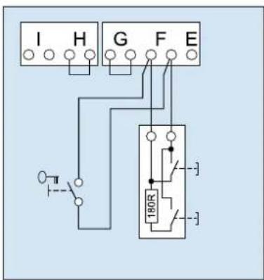
text_image
I H G F E 180R3. Ingang STOP A
text_image
I H G F E4. Ingang STOP B
text_image
I H G F E REL LS γ LS + - +text_image
I H G F E LS2 1 2 LS2 1 25. Voedingsspanning 24 V DC, maximaal 100 mA (geschakeld)
text_image
I H G F E 24V-6. Voedingsspanning 24 V DC, maximaal 100 mA (geschakeld)
text_image
Diagram showing a parking tag with 'P' and placeholder text, likely indicating parking or parking-related items.natural_image
Illustration of a finger pressing down on a padlock and three triangular buttons (no text or symbols)Menu 3 + menu 4:
De eindposities instellen
flowchart
graph TD
    A["Device Icon"] --> B["Triangle Shape B"]
    A --> C["Triangle Shape C"]
    B --> D["Box with Down Arrow"]
Kracht aanleren

Waarschuwing:
flowchart
graph TD
    A["Component B"] --> B["Component C"]
    B --> C["Component D"]
    C --> D["Arrow pointing downward"]
De krachtbegrenzing controleren
text_image
F < 400N 50mmnatural_image
Illustration of a hand holding a small rectangular object with a grid-like pattern, no text or symbols present.Cycliteller
text_image
Technical diagram of a structural framework with numbered components and an inset showing connection detailstext_image
Technical diagram of a mechanical assembly with numbered components and safety warning symbolstext_image
Technical diagram showing three labeled mechanical components (I, II, III) mounted on parallel lines with directional arrows indicating motion or force.text_image
I H G F E Y
text_image
I H G F E 180R3. Entrée STOP A
text_image
I H G F E4. Entrée STOP B
text_image
I H G F E REL LS LS + - +text_image
I H G F E LS2 1 2 LS2 1 2text_image
I H G F E 24V-text_image
Diagram showing a parking tag icon with 'P' label and placeholder texttext_image
A1 B C D → → → → → →Menu 2 :
Programmer 4 minutes de lumière
natural_image
Illustration of a finger pressing down on a padlock and three triangular buttons (no text or symbols)Menu 3 + menu 4 :
text_image
F< 400N 50mmnatural_image
Illustration of a hand pressing a small rectangular object on a circular surface (no text or symbols)Compteur de cycles
text_image
Technical diagram of a cable or electrical connector assembly with numbered components and an inset showing connection details.* Eksemplarisk visning af garageport
text_image
Technical diagram of a mechanical assembly with numbered components and safety warning symbolstext_image
I H G F E Y2. Ekstern impulsgiver
text_image
I H G F E 180R3. Indgang STOP A
Via denne indgang stoppes drevet hhv. undertrykkes start.