
WH-SDC09C3E5-1 - Air Conditioning PANASONIC - Free user manual and instructions
Find the device manual for free WH-SDC09C3E5-1 PANASONIC in PDF.

| Brand | Panasonic |
| Model | WH-SDC09C3E5-1 |
| Product type | Air-to-water heat pump split (heating and cooling) |
| Indoor unit | Indoor installation only |
| Outdoor unit | Outdoor installation, operating range -20°C to +43°C |
| Power supply | 230 V ~ 50 Hz with integrated residual current circuit breaker (RCCB) |
| Water outlet temperature range (heating) | 25°C to 55°C |
| Water outlet temperature range (cooling) | 5°C to 20°C |
| Outdoor ambient temperature range (heating) | -20°C to +35°C |
| Outdoor ambient temperature range (cooling) | +16°C to +43°C |
| Operating water pressure | 0.05 to 0.3 MPa (0.1 MPa = 1 bar) |
| Operating modes | Heating, cooling, domestic hot water tank, heating + tank, cooling + tank |
| Special functions | Silent mode, backup heating, sterilization, weekly timer (6 programs/day) |
| Control panel | LED display, touch keys, temperature adjustment, clock, timer |
| Domestic hot water tank connection | Possible (Panasonic tank recommended) |
| Indoor backup heating capacity | 3 kW / 6 kW / 9 kW (selectable) |
| Water circuit antifreeze function | Yes (enabled/disabled) |
| Maintenance and cleaning | Clean external filter at least once a year, no water on the panel, soft dry cloth |
| Safety | RCCB, earthing, automatic stop in case of anomaly |
| Repairability | Interventions reserved for an authorized dealer (internal parts, installation, repair) |
| Warranty | Follow installation and use instructions for validity |
Frequently Asked Questions - WH-SDC09C3E5-1 PANASONIC
User questions about WH-SDC09C3E5-1 PANASONIC
0 question about this device. Answer the ones you know or ask your own.
Ask a new question about this device
Download the instructions for your Air Conditioning in PDF format for free! Find your manual WH-SDC09C3E5-1 - PANASONIC and take your electronic device back in hand. On this page are published all the documents necessary for the use of your device. WH-SDC09C3E5-1 by PANASONIC.
USER MANUAL WH-SDC09C3E5-1 PANASONIC
natural_image
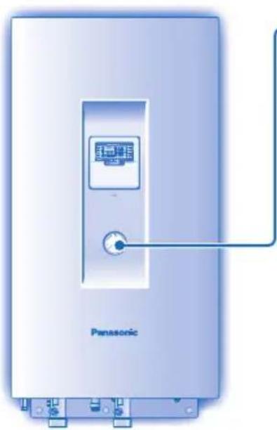
Front view of a Panasonic air conditioner unit with control panel and indicator lights (no text or symbols on the device itself)Panasonic®
Operating Instructions Air-to-Water Heatpump
Model No.
Indoor Unit Outdoor Unit
WH-SDC07C3E5 WH-UD07CE5-A
WH-SDC09C3E5 WH-UD09CE5-A
WH-SDC12C6E5 WH-UD12CE5-A
WH-SDC14C6E5 WH-UD14CE5-A
WH-SDC16C6E5 WH-UD16CE5-A
Before operating the unit, read these operating instructions thoroughly and keep them for future reference.
Before operating the unit, make sure the installation has been carried out correctly by authorized dealer correctly and precisely following the installation instructions given.
FRANÇAIS 12 - 21
© Panasonic Appliances Air-Conditioning Malaysia Sdn. Bhd. 2012. Unauthorized copying and distribution is a violation of law.
Thank you for purchasing Panasonic Product
TABLE OF CONTENTS
SAFETY PRECAUTIONS
2\~3
CONTROL PANEL
4\~8
INDOOR UNIT
9
TROUBLESHOOTING
10
INFORMATION
11
NOTE
The illustrations in this manual are for explanation purposes only and may differ from the actual unit. They are subjected to change without notice for future improvement.
OPERATION CONDITION
| Water outlet Temperature (°C) | Indoor | |
| HEATING | Max. 55 | |
| Min. 25 | ||
| COOLING | Max. 20 | |
| Min. 5 | ||
| Ambient Temperature (°C) | Outdoor | |
| HEATING | Max. 35 | |
| Min. -20 | ||
| COOLING | Max. 43 | |
| Min. 16 | ||
NOTICE : When the outdoor temperature is out of the above temperature range, the heating capacity will drop significantly and outdoor unit might stop for protection control. The unit will restart automatically after a short time when the outdoor temperature is back in the limits.
SAFETY PRECAUTIONS
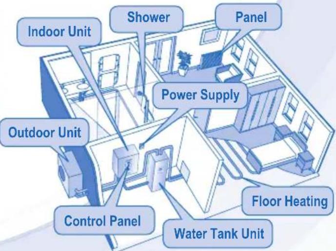
- Panasonic Air-to-Water Heatpump is a split system consisting only of an indoor unit and an outdoor unit. This system designed for combination with Panasonic Tank Unit. In case of non-Panasonic Tank Unit is being used with Panasonic Air-to-Water Heatpump System, Panasonic cannot guarantee neither good operation nor reliability of the system.
- This manual describes how to operate the Heatpump system between indoor and outdoor units only.
- Other operation such as water tank, radiator, external thermo controller and underfloor system, please refer to respective manufacturer operation manuals.
To prevent personal injury, injury to others, or property damage, please comply with the following. Incorrect operation due to failure to follow instructions below may cause harm or damage, the seriousness of which is classified as below:

WARNING
This sign warns of death or serious injury.

CAUTION
This sign warns of injury or damage to property.
The instructions to be followed are classified by the following symbols:

This symbol denotes an action that is PROHIBITED.


These symbols denote an action that is COMPULSORY.

WARNING
INDOOR UNIT AND OUTDOOR UNIT

This appliance is not intended for use by persons (including children) with reduced physical, sensory or mental capabilities, or lack of experience and knowledge, unless they have been given supervision or instruction concerning use of the appliance by a person responsible for their safety. Children should be supervised to ensure that they do not play with the appliance.
Please consult authorized dealer or specialist to clean the internal parts, repair, install, remove and reinstall the unit. Improper installation and handling will cause leakage, electric shock or fire.
Confir rm to authorized dealer or specialist on usage of specifi ed refrigerant type. Using of refrigerant other than the specifi ed type may cause product damage, burst and injury etc.

Do not install the unit in a potentially explosive or fl ammable atmosphere. Failure to do so could result in fi re.
Do not insert your fingers or other objects into the indoor or outdoor unit, rotating parts may cause injury.

Do not touch the outdoor unit during lightning, it may cause electric shock.
 WARNING WARNING | |
| INDOOR UNIT AND OUTDOOR UNIT | |
Do not sit or step on the unit, you may fall down accidentally.  | |
| Do not install the indoor unit at outdoor. This is designed for indoor installation only. | |
| POWER SUPPLY | |
| Do not use a modifi ed cord, joint cord, extension cord or unspecifi ed cord to prevent overheating and fi re. | |
| To prevent overheating, fi re or electric shock:Do not share the same power outlet with other equipment.Do not operate with wet hands.Do not over bend the power supply cord. | |
| If the supply cord is damage, it must be replaced by the manufacturer, its service agent or similarly qualifi ed persons in order to avoid a hazard. | |
| This unit is equipped with Residue Current Circuit Breaker (RCCB). It is strongly recommended to check the operation of the RCCB after installation and periodically after servicing or maintenance by authorized dealer to ensure it is in good working order. Otherwise, it may cause electrical shock or fi re in case of malfunction. | |
| It is strongly recommended to install Residual Current Device (RCD) on-site to prevent electric shock or fi re. | |
| Stop using the product if any abnormality/failure occurs and disconnect the power plug or turn off the power switch and breaker.(Risk of smoke/fi re/electric shock)Examples of abnormality/failureThe RCCB switches off by itself.Burning smell, abnormal noise or vibration sound is observed when the unit is in use.Hot water keeps on coming off the unit.Contact your local dealer immediately for maintenance/repair. | |
| It is recommended to wear gloves during servicing or maintenance in order to avoid hazard. | |
| This equipment must be earthed to prevent electrical shock or fi re. | |
| Prevent electric shock by switching off the power supply when:- Before cleaning or servicing.- Extended non-use. | |
| This appliance is for multiple uses. All power supply circuits must be turn off before access to any of the terminals in the indoor unit, to avoid electrical shock, burn or fatal injury. | |
| CAUTION | |
| INDOOR UNIT AND OUTDOOR UNIT | |
| Do not wash the indoor unit with water, benzene, thinner or scouring powder. | |
| Do not install the unit close to any combustible equipment or at bathroom. Otherwise, it may cause electric shock or fi re. | |
| Do not touch the water discharge pipe at the indoor unit during operation. | |
| Do not place anything on top or beneath of the unit. | |
| Do not touch the sharp aluminium fi n, sharp parts may cause injury. | |
| Do not use the system during sterilization to prevent scalding or overheat during shower. | |
| Ensure drainage pipe is connected properly. Otherwise, leakage may occur. | |
| After a long period of use, make sure the installation rack does not deteriorate to prevent the unit from falling down. | |
| The sterilization function fi eld settings must be confi gured by the authorized dealer according to local laws and regulation. | |
| CONTROL PANEL | |
| Do not let the control panel get wet. Otherwise, it may cause electric shock or fi re. | |
| Do not press the buttons on the control panel with hard, pointed objects. Otherwise, it may damage the unit. | |
| Do not wash the control panel with water, benzene, thinner or scouring powder. | |
| Do not inspect or service the control panel by yourself. Please consult authorized dealer. Otherwise, it may cause injury if mishandling. | |
CONTROL PANEL
• Some functions describe in this manual may not be applicable to your unit.
- Consult your nearest authorized dealer for further information.
- For normal operation, the ERROR RESET, FORCE and SERVICE buttons are not in use.

Open cover for buttons selections.
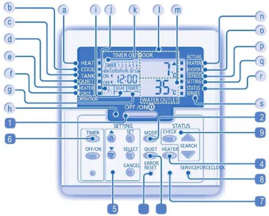
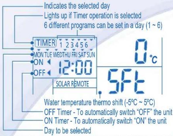
CONTROL PANEL'S DISPLAY
a Heat Mode OFF/ON Indicator
b Cool Mode OFF/ON Indicator
c Tank Mode Indicator
d Quiet Mode Indicator
e Backup Heater Enabled/Disabled Indicator
f Force Heater Request OFF/ON Indicator
g External Thermo Controller Connected Display
h Operation LED
i Solar Display
j Caution (Tank Temperature above 60°C) Indicator
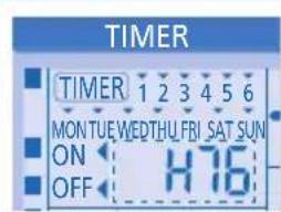
k Timer/Clock Setting Display
1 Outdoor Ambient Temperature Display
m Water Outlet Temperature Display
n Backup Heater Actual (OFF/ON) Indicator
o Booster Heater Actual (OFF/ON) Indicator
p System Defrost Operation OFF/ON Indicator
q System Setting Mode OFF/ON Indicator
r System Status Check Mode OFF/ON Indicator
s System Service Mode OFF/ON Indicator
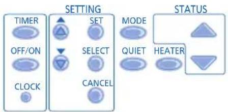
CONTROL PANEL'S BUTTON
1 OFF/ON Button
2 Operation Mode Button
3 Quiet Operation Button
4 Indoor Unit Backup Heater Enabling Button
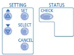
5 System Setting Mode Buttons
6 Timer Setting Group Buttons
7 Force Heater Mode Button
8 System Service Mode Button
9 System Status Check Button
10 Error Reset Button
CONTROL PANEL PREPARATION
Setting Current Day and Time
CLOCK
- Press

to set current day.
- Press
SET to confirm.
- Press
t steps 2 and 3 to set the current time.
Notes:
• The current day and time need to be set when:
- The power is turned on for the first time.
- After a long time has elapsed since the power was last turned on.
- The current time that has been set will be the standard time for all the Timer operations.
SETTING UP THE SPECIAL FUNCTIONS
• After initial installation, you can manually adjust the settings. The initial setting remains active until the user changes it.
- The control panel can be used for multiple installations. Some functions may not be applicable to your unit.
- Ensure the operation LED is in OFF condition before setting.
-
Press SET and CHECK simultaneously for 5 seconds to enter special setting mode. "SETTING" and "STATUS" indicator is ON.
-
Press ▲ or ▼ to browse functions.
- Press SELECT to enter function.
- Press ⬆ or ⬇ to enable YES or disable NO function, or set other options.
- Press SET to confirm.
Set Control Panel's Display Description
| 1 | ro on | con | External Thermo Controller (YES / NO)To set external thermo controller connection. |
| 2 | HEATER | CAP | Indoor Backup Heater Capacity Selection (3kW / 6kW / 9kW)To reduce the heater power whenever unnecessary. Options vary depending on model. |
| 3 | Ant | FrE | Water System Freeze Prevention Function (YES / NO)To activate or deactivate water system freeze prevention function when unit is OFF. |
| 4 | TANK | con | Tank Connection (YES / NO)To set tank connection.Note: If select “Tank connection” is “NO”, Set 5 ~ 14 are skipped. |
| 5 | SOLAR | Pry | Solar Priority (YES / NO)To choose the solar use for water tank heat up. |
| 6 | COOL | Pry | Cooling Priority (YES / NO)To choose the room cooling as priority during COOL + TANK mode.If select “Cooling priority” is “YES”, Set 8 ~ 9 are irrelevant to COOL + TANK mode. |
| 7 | HEAT | Pry | Heating Priority (YES / NO)To choose the room heating as priority during HEAT + TANK mode.Note: If select “Heating priority” is “YES”, Set 8 ~ 9 are irrelevant to HEAT + TANK mode. |
| 8 | COOL/HEAT | int | Cooling/Heating operation Interval SetTo set timer for Cool mode or Heat mode during COOL + TANK mode or HEAT + TANK mode(0.5hour ~ 10 hours). If both “Heating priority” and “Cooling priority” are “YES”, Set 8 ~9 are skipped. |
| 9 | TANK | int | Tank Heat-up Interval SetTo set timer for Tank during COOL + TANK mode or HEAT + TANK mode(5minutes ~ 1hour 35minutes). |
| 10 | BOOSTER | htr | Booster Heater Function (YES / NO)To activate or deactivate tank booster heater functionNote: If select “Booster heater function” is “NO”, Set 11 is skipped. |
| 11 | BOOSTER | dly | Booster Heater Delay Timer SetTo set delay timer for booster heater to ON if water tank temperature is not reached(20minutes ~ 1hour 35minutes). |
- Do not use the system during sterilization to prevent scalding or overheat during shower.
- The sterilization function field settings must be configured by the authorized dealer according to local laws and regulation.
| 12 | 5t rL | Fun | Sterilization (YES / NO)To set sterilization, if required.Note: If select “Sterilization” is “NO”, set 13 ~ 15 are skipped. |
| 13 | 5tr | Sterilization Day & Time SetTo set timer for sterilization (only once a week, will operate even in standby condition). | |
| 14 | 5t rL | bo | Sterilization Temperature SetTo set temperature for sterilization function (40°C ~ 75°C). |
| 15 | 5tr | oPr | Sterilization Continue TimeTo set timer to maintain heating temperature in order to complete the sterilization function (5minutes ~ 1hour). |
BASIC OPERATION

TO TURN ON OR OFF THE UNIT
- When unit is ON, operation LED is lit and the actual temperature for water outlet and outdoor ambient are shown on the control panel display.

- To turn ON or OFF the panel/floor heating operation.
- In this mode, the outdoor unit will provide heating capacity to the indoor unit.
- HEAT + TANK MODE
- In this mode, the outdoor unit will provide heating capacity to the sanitary tank and indoor unit.
- This operation is not used when the sanitary water tank is not installed.
• TANK MODE
- To turn ON or OFF the sanitary tank operation.
- In this mode, the outdoor unit will provide heating capacity to the sanitary tank.
- COOL MODE
- To turn ON or OFF the panel operation.
- In this mode, the outdoor unit will provide cooling capacity to the indoor unit.
- COOL + TANK MODE
- In this mode, the outdoor unit will provide cooling capacity to the indoor unit.
- Indoor unit will control booster heat in sanitary tank.

TO ENJOY QUIET ENVIRONMENT
- This operation reduces outdoor unit noise. In this condition, it may cause decrease in heating/cooling capacity.

TO ENABLE THE BACKUP HEATER
- The backup heater provides extra heating capacity during cold outdoor temperature and only can operate at heat mode operation for indoor unit when he was enabled by pushing this button.
• The backup heater will automatically turn ON when the setting conditions is fulfilled.
• To disabled the Heater operation manually, press the respective button again.

SYSTEM STATUS CHECK MODE
- Press CHECK for 5 seconds to enter STATUS mode.
- Press ▲ or ▼ to check the Water Inlet Temperature, Tank Temperature, Compressor Running Frequency or Error History.
- Press CANCEL to exit STATUS mode.
- Once STATUS mode is entered, "STATUS" indicator is ON.
- STATUS mode cannot be activated when the "SETTING" indicator is ON.
ADVANCE OPERATION
- It is strongly recommended to contact the nearest authorized dealer to change the water temperature range.
- Using the control panel could set the temperature range for water outlet temperature and outdoor ambient temperature.
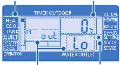
SYSTEM SETTING MODE

Operation Mode Temperature display
flowchart
graph TD
    A["TIMER OUTDOOR"] --> B["HEAT COOL TANK QUIET"]
    B --> C["HEATER FORCE OPERATION"]
    C --> D["OUT"]
    D --> E["Water OUTLET"]
    E --> F["ACTUAL HEATER BOOSTER DEFROST SETTING STATUS SERVICE"]
    style A fill:#4CAF50,stroke:#333
    style F fill:#2196F3,stroke:#333
Parameter *
SETTING indicator
- Press SET for 5 seconds to enter "SETTING" mode. "SETTING" indicator is ON.
- Press ▲ or ▼ to choose a parameter.
- After selecting the desired parameter, press SELECT to enter the parameter.
- Press ▲ or ▼ to set the desired temperature.
- Press SET again to confirm the setting.
- Repeat steps 2 to 5 to set other parameters.
Operation Mode Parameter * Description
| HEAT | out Lo | Low outdoor ambient set temperature (-15°C ~ 15°C). |
| HEAT | out Hi | High outdoor ambient set temperature (-15°C ~ 15°C). |
| HEAT | H20 Lo | Water outlet set temperature at low outdoor ambient temperature (25°C ~ 55°C). |
| HEAT | H20 Hi | Water outlet set temperature at high outdoor ambient temperature (25°C ~ 55°C). |
| HEAT | OFF | Set temperature for turning OFF heating operation (5°C ~ 35°C). |
| HEATER | out on | Outdoor ambient set temperature for turning ON heater operation (-15°C ~ 20°C). |
| COOL | SET | Water set temperature during cool mode (5°C ~ 20°C) |
| TANK | SET | Sanitary tank set temperature (40°C ~ 75°C). |
WATER TEMPERATURE THERMO SHIFT SETTING
- Press SET within 5 seconds.
- Repeat steps 3 to 5 to set the desired shift temperature (-5^ 5^) .
Notes:
- Press 📋 or wait 30 seconds to exit "SETTING" mode.
- The setting temperature will be stored in the system once confirm.
- "SETTING" mode cannot be activated when the "SERVICE" and "STATUS" indicator is ON.
WEEKLY TIMER SETTING
flowchart
graph TD
    A["TIMER"] --> B["SET"]
    C["OFF/ON"] --> D["SELECT"]
    E["CLOCK"] --> F["CANCEL"]
    G["MODE"] --> H["QUIET"]
    I["HEATER"] --> J["STATUS"]
Function Step
| Enter timer mode | PressTIMER. |
| Set day & time | 1. Pressor to select your desired day.2. PressSELECTto confi rm.3. “1” will be blinking, pressSELECTto set program 1.4. PressOFF/ONto select ON or OFF timer.5. Pressor to select your desired time.You can setMODE, QUIET, HEATERand desired shift temperaturewith timer.6. PressSETto confirm program 1. The selected day will be highlighted with▼.After 2 seconds, the display will move to the next program.7. Repeat steps 4 to 7 to set programs 2 to 6.During timer setup, if no button is pressed within 30 seconds, or if theSETbutton is pressed the setting at that moment is confirmed and timer setup is ended. |
| Add/Modify timer | Repeat the steps above. |
| Disable timer | PressTIMER, then pressCANCEL. |
| Enable timer | PressTIMER, then pressSET. |
| Check timer | 1. PressTIMER.2. Pressor until your desired day is shown, pressSELECTto confi rm your selection.3. Pressor to check the set programs. |
| Cancel timer | 1. PressTIMER.2. Pressor until your desired day is shown, pressSELECTto confi rm your selection.3. Pressor to enter program setting.4. Pressor until your desired program is shown.5. PressCANCELto cancel the program. |
Notes:
- You can set the Timer for each day of the week (Monday to Sunday) with 6 programs per day.
- When the unit is switched on by the ON TIMER, it will use the previously set temperature to control the water outlet temperature.
- Same timer program cannot be set in the same day.
- You may also select collective days with same timer setting.
- Promotes energy saving by allowing you to set up to 6 programs in any given day.
- Switch off the power supply before cleaning.
CLEANING INSTRUCTIONS
- Do not use benzene, thinner or scouring powder.
- Use only soap (pH7) or neutral household detergent.
- Do not use water hotter than 40^ C .
HINT
- To ensure optimal performance of the unit, cleaning maintenance has to be carried out at regular intervals. Please consult authorized dealer.
natural_image
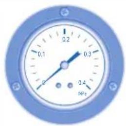
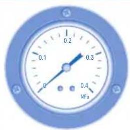
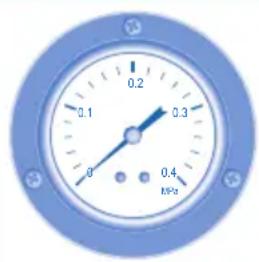
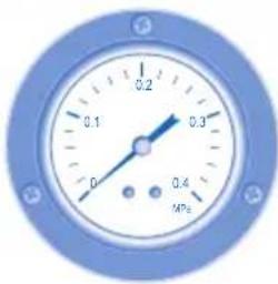
Front view of a Panasonic air conditioner unit with control panel and indicator lights (no text or symbols on the device itself)WATER PRESSURE GAUGE

natural_image
Close-up of a blue industrial pressure gauge with needle pointing to 0.3 MPa (no text or symbols beyond measurement markings)
- Do not press or hit the glass cover with hard, pointed objects. This may damage the unit.

- Ensure that the water pressure is between 0.05 to 0.3 MPa (0.1 MPa = 1 bar).
• In case the water pressure is out of the above range, please consult authorized dealer.
INDOOR UNIT & CONTROL PANEL
- Do not splash water directly.
- Wipe the unit gently with a soft, dry cloth.
EXTERNAL FILTER
- Please clean the external filter at least once a year. Fail to do so might cause filter clogged, consequent system breakdown. Please consult authorized dealer.
OUTDOOR UNIT
- Do not obstruct the air inlet and air outlet vents, it may cause low performance or breakdown. Please remove obstacles to assure the ventilation.
- During winter, please clean and remove the snow near outdoor unit so that the snow does not cover the air inlet and air outlet vents.
INSPECTION
- In order to ensure optimal performance of the unit, seasonal inspections on the unit, external filter and field wiring have to be carried out at regular intervals. This maintenance should be carried out by authorized dealer.
- Clear any obstruction at the air inlet and air outlet vents of outdoor unit.
FOR EXTENDED NON-USE
- Turn off the power supply.
NON SERVICEABLE CRITERIAS
TURN OFF POWER SUPPLY then please consult authorized dealer under the following conditions:
• Abnormal noise during operation.
• Water/foreign particles have entered the control panel.
• Water leaks from Indoor unit.
• Circuit breaker switches off frequently.
• Power cord becomes unnaturally warm.
TROUBLESHOOTING
The following symptoms do not indicate malfunction.
| SYMPTOM | CAUSE | |
| Flowing sound during operation. | ▶ | Refrigerant flow inside the unit. |
| Operation is delayed a few minutes after restarting. | ▶ | The delay is a protection to the unit's compressor. |
| Outdoor unit emits water/steam. ▶ Condensation or evaporation occurs on pipes. | ||
| Outdoor unit emits steam during heating mode. | ▶ | This is due to defrost operation happens at the heat exchanger. |
| Outdoor unit does not operate. ▶ When the outdoor temperature is out of the operation condition range, the heatpump system enter protection control. | ||
| Air-to-Water Heatpump system operation will turn off. | ▶ | The heatpump system enter protection control. Compressor stops by water inlet temperature lower than 18°C; and backup heater power turn on by water inlet temperature lower than 23°C. |
| System diffi cult to heat-up. ▶ | • | When heating is operated by indoor unit together with fl oor heating or panel heater simultaneously, there may be case where warm water temperature is getting lower and cause fl oor heating or panel heater heat-up is weaken.When outdoor air temperature is low, it may be diffi cult to get warm.Is the snow pile blocking the discharge outlet or intake inlet of outdoor unit.When water outlet set temperature is low, it may be diffi cult to get warm. |
| System cannot get warm instantly. ▶ Due to the nature of the heatpump system, it may take some time to heat-up the water if the unit is operated from cold-start. | ||
| Backup heater turn ON automatically when it is not enabled. | ▶ | The turn ON of backup heater is a protection to the indoor unit's heat exchanger. |
| Operation starts automatically even without ON Timer. | ▶ | The sterilization timer has been set. |
Check the following before calling for servicing.
| SYMPTOM | CHECK |
| Heating/cooling operation is not working efficiently. | Set the temperature correctly.Is the panel heater/cooler valve closed.Clear any obstruction at the air inlet and air outlet vents of outdoor unit. |
| Noisy during operation. | Check if the unit has been installed at an incline or the cover is not closed properly. |
| The unit does not work. | Check if the circuit breaker is tripped. |
| Operation LED is no lit or control panel display is blank. | Is the power supply off or power failure. |
The operation LED blinks and error code appear on control panel display.
Force Heater Mode Button

- In case of a failure of the Air-to-Water Heatpump system, the backup heater can be used to heat up the heating water. Press FORCE to switch on the backup heater.
- Press OFF/ON to stop the force heater operation.
- During Force Heater mode, all other operations are not allowed.
Information for Users on Collection and Disposal of Old Equipment
These symbols on the products, packaging, and/or accompanying documents mean that used electrical and electronic products should not be mixed with general household waste.
For proper treatment, recovery and recycling of old products, please take them to applicable collection points, in accordance with your national legislation and the Directives 2002/96/EC and 2006/66/EC.
By disposing of these products correctly, you will help to save valuable resources and prevent any potential negative effects on human health and the environment which could otherwise arise from inappropriate waste handling.
For more information about collection and recycling of old products, please contact your local municipality, your waste disposal service or the point of sale where you purchased the items.
Penalties may be applicable for incorrect disposal of this waste, in accordance with national legislation.
For business users in the European Union
If you wish to discard electrical and electronic equipment, please contact your dealer or supplier for further information.
[Information on Disposal in other Countries outside the European Union]
These symbols are only valid in the European Union. If you wish to discard these items, please contact your local authorities or dealer and ask for the correct method of disposal.
natural_image
Front view of a Panasonic air conditioner unit with control panel and indicator lights (no text or symbols on main body)JAUGE DE PRESSION D'EAU
![PANASONIC WH-SDC09C3E5-1 - [Information on Disposal in other Countries outside the European Union] - 1](/content/2026/04/670232/images/9a2fa7bfcc7c2b2a3396ff7c9bb4092c1fab731df6d8942e2a722876b2785b7e.jpg)
natural_image
Close-up of a blue industrial pressure gauge with needle pointing at 0.3 MPa (no text or symbols beyond measurement markings)![PANASONIC WH-SDC09C3E5-1 - [Information on Disposal in other Countries outside the European Union] - 2](/content/2026/04/670232/images/2368369a85039f5f8dfb75d1d0ad65835bfe993d3eedff3d7c47133a0490a69c.jpg)

natural_image
Front view of a Panasonic air conditioner unit with control panel and indicator lights (no text or symbols on the device itself)natural_image
Close-up of a blue pressure gauge with scale markings (0.1, 0.2, 0.3, 0.4 MPa) and adjustment knobs at the top (no text or symbols beyond measurement labels)![PANASONIC WH-SDC09C3E5-1 - [Information on Disposal in other Countries outside the European Union] - 4](/content/2026/04/670232/images/b061405ee408754dac6937b71b40ddb64f5bc36508e97b94f278ac4429c488e2.jpg)

natural_image
Illustration of a Panasonic air conditioner unit with control panel and indicator lights (no text or symbols on the device itself)MANOMETER FÜR WASSERDRUCK

natural_image
Close-up of a blue industrial pressure gauge with needle and two terminal points (no text or symbols visible)

UNITÀ INTERNA E UNITÀ ESTERNA

natural_image
Front view of a Panasonic air conditioner unit with control panel and indicator lights (no text or symbols on main body)MANOMETRO DI PRESSIONE DELL'ACQUA.

natural_image
Illustration of a Panasonic industrial control panel with a central display and terminal blocks (no text or symbols on the panel itself)WATERDRUKMETER


BINNEN-UNIT & CONTROLEPANEEL
natural_image
Front view of a Panasonic air conditioner unit with control panel and indicator lights (no text or symbols on main body)MANÓMETRO DA ÁGUA


natural_image
Front view of a Panasonic industrial air conditioner unit with control panel and indicator lights (no text or symbols on main body)ΕΥΡΟΣ ΠΙΕΣΗΣ ΝΕΡΟΥ
natural_image
Close-up of a blue industrial pressure gauge with scale markings (no text or symbols beyond measurement labels)

VOLBA PROVOZNÍHO REŽIMU


- REŽIM HEAT (TOPENÍ)
ČINNOST ZÁLOŽNÍHO TOPENÍ
REŽIM PROVĚRKY STAVU SYSTÉMU
natural_image
Front view of a Panasonic air conditioner unit with control panel and indicator lights (no text or symbols on main body)UKAZATEL TLAKU VODY
natural_image
Close-up of a blue industrial pressure gauge with needle pointing to 0.3 (no text or symbols beyond measurement markings)

Authorized representative in EU
Panasonic Testing Centre
Panasonic Marketing Europe GmbH
Winsbergring 15, 22525 Hamburg, Germany