
WSE5000-Multi - Welding machine SCHEPPACH - Free user manual and instructions
Find the device manual for free WSE5000-Multi SCHEPPACH in PDF.

| Product type | Multi-process welding machine (MIG/MMA/LIFT TIG) |
| Brand | Scheppach |
| Model | WSE5000-Multi |
| Dimensions (L x W x H) | 415 x 201 x 249 mm |
| Weight | 5.3 kg |
| Power supply voltage | 230 V~ / 50-60 Hz |
| Power consumption | 5.75 kW |
| MIG welding current | 30 - 160 A |
| MMA welding current | 10 - 140 A |
| LIFT TIG welding current | 10 - 200 A |
| Duty cycle (20%) | 160 A (MIG) / 140 A (MMA) / 200 A (LIFT TIG) |
| Welding wire diameter | 0.6 - 1.0 mm |
| Max wire spool weight | 5 kg |
| Protection rating | IP21S |
| Insulation class | F |
| Cooling type | Fan (AF) |
| Welding functions | MIG/MAG, MMA, LIFT TIG |
| Included accessories | Welding torch set, wire rolls (2x), contact tips (4x), electrodes (5x), ground clamp, electrode holder, welding helmet, brush/hammer |
| Maintenance | Regular exterior cleaning, check connections, internal maintenance by a professional |
| Safety | Thermal protection, On/Off switch, operation and overheating indicator lights |
| Wear parts | Electrode holder, ground terminal, contact tip, torch nozzle |
| Warranty | Legal (CE conformity) |
Frequently Asked Questions - WSE5000-Multi SCHEPPACH
User questions about WSE5000-Multi SCHEPPACH
0 question about this device. Answer the ones you know or ask your own.
Ask a new question about this device
Download the instructions for your Welding machine in PDF format for free! Find your manual WSE5000-Multi - SCHEPPACH and take your electronic device back in hand. On this page are published all the documents necessary for the use of your device. WSE5000-Multi by SCHEPPACH.
USER MANUAL WSE5000-Multi SCHEPPACH
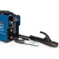
natural_image
Exterior view of a black Schneppach industrial testing device with control knobs and buttons (no readable text beyond branding)
WSE5000-Multi
| DE | Digitales MultischweißgerätOriginalbedienungsanleitung | 07 |
| GB | Digital multi welding machineTranslation of the original operating manual | 26 |
| FR | Machine à souder numérique multifonctionTraduction du mode d'emploi original | 42 |
| IT | Saldatrice multiprocesso digitaleTraduzione delle istruzioni per l'uso originali | 60 |
| NL | Digitaal multi lasapparaatVertaling van de originele gebruikshandleiding | 77 |
| ES | Equipo de soldadura multifunción digitalTraducción del manual de instrucciones original | 94 |
| PT | Máquina digital de soldadura multiprocessoTradução do manual de operação original | 112 |
natural_image
Technical diagram of a black plastic housing component with labeled parts (a, b, c), showing internal structure and mounting points (no text or symbols beyond labels)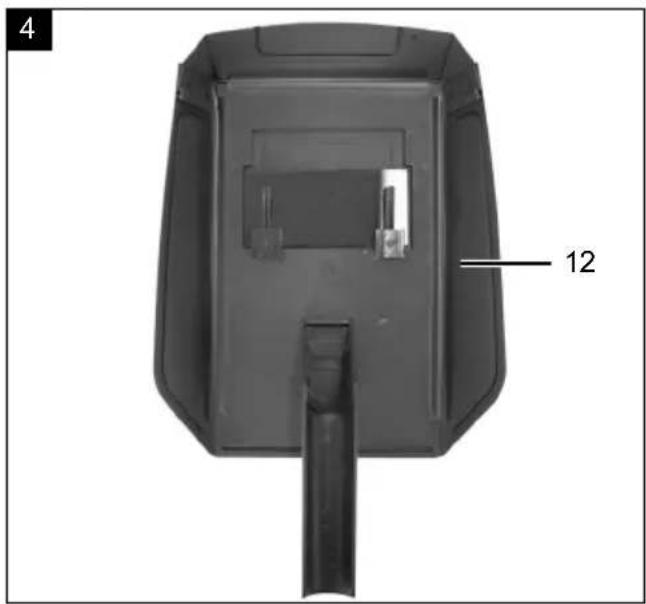
natural_image
Technical illustration of a mechanical suspension and probe with labeled component '27' (no text or symbols beyond label)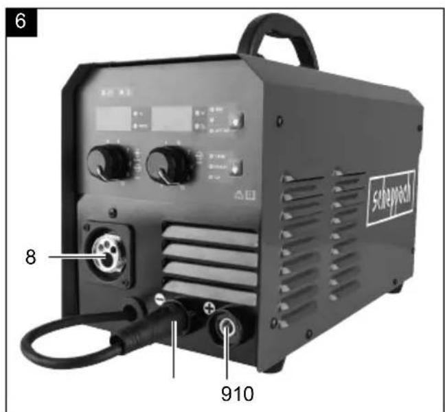
natural_image
Black industrial machine with control panel and mechanical components (no visible text or symbols)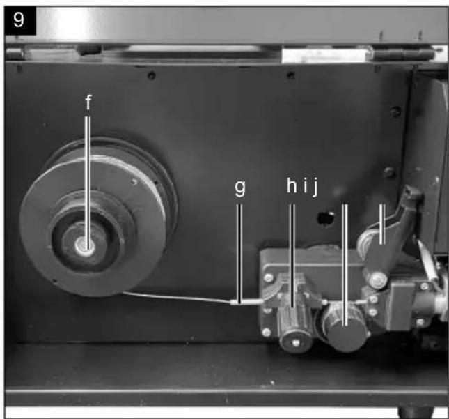
Günzburger Straße 69
D-89335 Ichenhausen
Verehrter Kunde
Homepage: https://www.scheppach.com/de/service
Explanation of the symbols on the device
Symbols are used in this manual to draw your attention to potential hazards. The safety symbols and the accompanying explanations must be fully understood. The warnings themselves will not rectify a hazard and cannot replace proper accident prevention measures.
 | Read the operating and safety instructions before start-up and follow them! |
| EN 60974-1 | European standard for welding machines for manual arc welding with limited duty cycle. |
| Single-phase, static frequency, converter transformer rectifier | |
 | Symbol for manual arc welding with coated rod electrodes (MMA) |
 | Metal inert and active gas welding including the use of flux-cored wire (MIG) |
 | Symbol for tungsten inert gas welding (LIFT TIG) |
 | Direct current |
 | Suitable for welding under increased electrical risk |
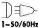 | Mains input; Number of phases as well as alternating current symbol and rated value of the frequency |
| [4888] | Rated idle voltage |
| [4276] | Mains voltage |
| [3844] | Duty cycle |
| I_2 | Welding current |
| U_2 | Welding voltage [V] |
| I_max | highest rated of mains current |
| I_eff | Effective value of the largest mains current [A] |
| IP21S | Protection category |
| B | Insulation class |
 | Caution! Risk of electric shock! |
 | Electric shock from the welding electrode can be fatal |
 | Inhaling welding fumes can be hazardous to health. |
 | Electromagnetic fields can interfere with the function of pacemakers. |
 | Welding sparks can cause an explosion or fire. |
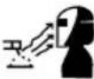 | Arc rays can damage the eyes and the skin. |
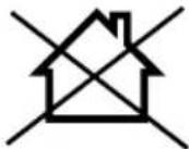
 | Do not use the device outdoors and never in the rain! |
| △ Attention! | We have marked points in these operating instructions that impact your safety with this symbol |
Table of contents: Page:
- Introduction....29
- Device description (Fig. 1)....29
- Scope of delivery 30
- Proper use 30
- General safety information 30
- Technical data.... 34
- Unpacking 35
- Assembly 35
- Before commissioning 36
- Start up 36
- Electrical connection 39
- Maintenance and cleaning 40
- Storage 40
- Disposal and recycling.... 40
- Troubleshooting 41
1. Introduction
Manufacturer:
scheppach
Günzburger Straße 69
D-89335 Ichenhausen
Dear Customer
We hope your new tool brings you much enjoyment and success.
Note:
In accordance with the applicable product liability laws, the manufacturer of this device assumes no liability for damage to the device or caused by the device arising from:
- Improper handling,
• Non-compliance with the operating manual, - Repairs carried out by third parties, unauthorised specialists.
• Installing and replacing non-original spare parts
• Application other than specified - Failure of the electrical system in the event of the electrical regulations and VDE provisions 0100, DIN 13 / VDE0113 not being observed
Please consider:
Read through the complete text in the operating manual before installing and commissioning the device.
The operating manual is intended to help the user to become familiar with the machine and take advantage of its application possibilities in accordance with the recommendations.
The operating manual includes important instructions for safe, proper and economic operation of the device, for avoiding danger, for minimising repair costs and downtimes, and for increasing the reliability and extending the service life of the device. In addition to the safety instructions in this operating manual, you must also observe the regulations applicable to the operation of the device in your country.
Keep the operating manual package with the machine at all times and store it in a plastic cover to protect it from dirt and moisture. They must be read and carefully observed by all operating personnel before starting the work.
The device may only be used by personnel who have been trained to use it and who have been instructed with respect to the associated hazards.
The required minimum age must be observed.
In addition to the safety instructions in this operating manual and the separate regulations of your country, the generally recognised technical rules relating to the operation of such machines must also be observed. We accept no liability for accidents or damage that occur due to a failure to observe this manual and the safety instructions.
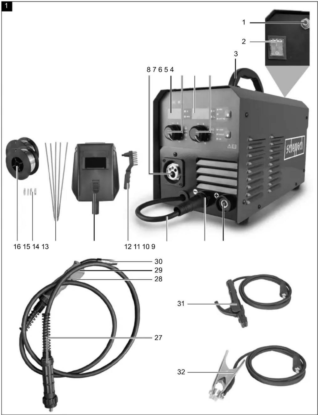
2. Device description (Fig. 1)
- Gas connection
- On/off switch
- Carrying handle
- Potentiometer for setting the welding current
- Welding current display
- Potentiometer for wire feed and for setting the electrical current
- Wire feed indicator
- Hose assembly connection (MIG/MAG)
- Quick coupling connection positive
- Quick coupling connection negative
- Quick coupling for polarisation change
- Combination wire brush with slag hammer
- Welding mask
- Rod electrodes (5x)
- Contact tip (4x)
- Welding wire reel (2x)
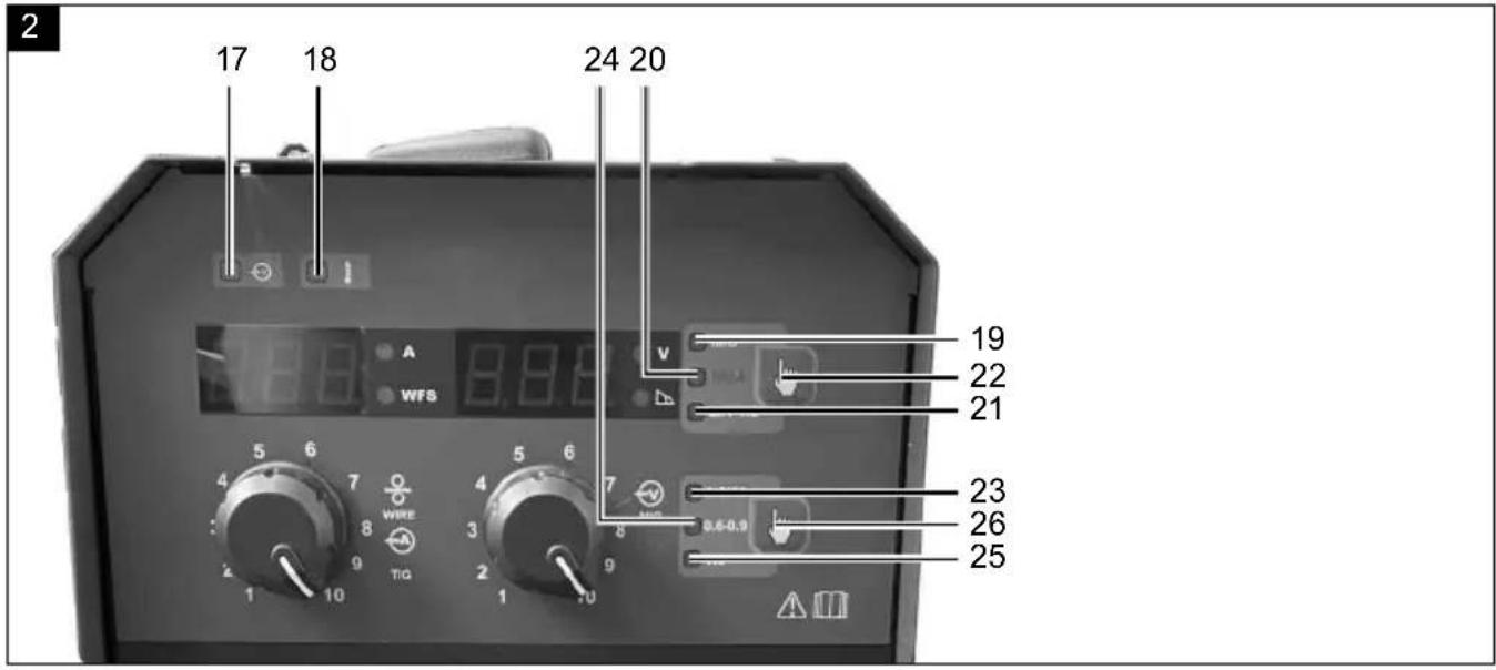
- Indicator lamp for operation
- Indicator lamp for overheating
- MIG welding process
- MMA welding process
- LIFT TIG welding process
- Selection button for welding process
- Welding wire diameter 1.0 /AI
- Welding wire diameter 0.6 - 0.9
- Welding wire diameter 1.0
- Selection button for welding wire diameter
- Hose assembly
- Burner button
- Burner
- Burner nozzle
- Electrode holder
- Earth clamp
3. Scope of delivery
- Operating manual
- Welding machine
- Hose assembly
• Welding wire reel (2x) - Contact tip (4x)
- Rod electrode (5x)
- Earth clamp
- Electrode holder
4. Proper use
This welding machine is suitable for welding metals such as carbon steel, alloy steel, other stainless steels, copper, aluminium, titanium etc. The product has an indicator lamp, a thermal protection display and a cooling fan. It is also equipped with a carrying strap for safe lifting and moving of the product.
The machine may only be used in the intended manner. Any use beyond this is improper. The user/operator, not the manufacturer, is responsible for damages or injuries of any type resulting from this.
The device may only be operated by qualified or instructed personnel. This includes persons who, due to their technical training, experience and knowledge of the relevant facilities, are able to assess the work assigned to them and recognize possible dangers or persons who are responsible for the assigned work and have been instructed about possible dangers due to careless behaviour.
Please observe that our equipment was not designed with the intention of use for commercial or industrial purposes.
We assume no guarantee if the equipment is used in commercial or industrial applications, or for equivalent work.
5. General safety information
⚠ WARNING! Read all safety warnings, instructions, illustrations and specifications provided with this power tool. Failure to follow all instructions listed below may result in electric shock, fire and/or serious injury.
Always observe
ATTENTION!
Only use the device as per its suitability, which is listed in these instructions.
Improper handling of this system can be dangerous for persons, animals and property. The system user is responsible for their own safety and that of other persons:
• Always read these usage instructions and observe the regulations.
- Repairs and/or maintenance work may only be carried out by qualified persons.
- Only the welding cables included in the scope of delivery or accessories recommended by the manufacturer may be used.
- Ensure that the device is looked after appropriately
- The device must not be constrained or stood directly against the wall during its functional life so that sufficient air can always be taken in through the opening slits. Make sure that the device is connected properly to the mains. Avoid any tensile stress on the mains cable. Unplug the device before setting it up in another location.
- Pay attention to the condition of the welding cable, the electrode holder and the earth clamp, wear on the insulation or on the parts carrying the electrical power can lead to a hazardous situation and reduce the quality of the welding work.
- Arc welding creates sparks, melted metal parts and smoke, therefore observe the following: Remove all flammable substances and/or materials from the workplace.
- Make sure that there is a sufficient air supply available.
- Do not weld on containers, vessels or pipes that have contained flammable liquids or gases. Avoid direct contact with the welding circuit. The off-load voltage arising between the electrode holder and the earthing clamp can be dangerous.
- Do not store or use the device in a damp or wet environment or in the rain
- Protect your eyes with specially designed protective glass (DIN grade 9-10). Use gloves and dry protective clothing that is free from oil and grease so that the skin is not exposed to the ultraviolet rays from the arc.
- Do not use the welding machine to thaw pipes.
Note!
- The light rays from the arc can damage the eyes and cause burns to the skin.
- Arc welding creates sparks and droplets of melted metal, the welded work piece begins to smoulder and remains very hot for a relatively long time.
- Arc welding releases vapours that are potentially harmful. Any electric shock can be potentially fatal.
- Do not come within 15 ~m of the arc.
- Protect yourself (and bystanders) in the vicinity from the potentially hazardous effects of the electric arc.
- Warning: Depending on the conditions of the mains power connection at the welding machine connection point, this can lead to disturbances in the mains for other consumers.
Attention!
Overloaded mains supplies and circuits can cause disturbances for other consumers while welding.
In case of doubt, the electricity supplier is to be consulted.
Sources of danger when arc welding
A series of hazard sources can arise when arc welding. It is therefore particularly important for the welder to observe the following rules in order not to endanger themselves and others and to avoid injuring persons and damaging the device.
- Work on the mains voltage side, e.g. on cables, connectors, sockets, etc., may only be carried out by a specialist. This applies in particular when creating intermediate cables.
- In the event of an accident, disconnect the welding power source from the mains immediately.
- If electrical contact voltages occur, switch off the device immediately and have it checked by a specialist.
• Always ensure that the electrical contacts on the welding current side are good.
- Always wear insulated gloves on both hands when welding. These protect rays electric shocks (off-load voltage of the welding current circuit), harmful rays (heat and UV rays) and smouldering metal and slag splashes.
- Wear sturdy, insulated footwear; the shoes should also insulate when wet. Low shoes are not suitable as smouldering metal drops that fall cause burns.
- Wear suitable clothing, no synthetic clothing.
- Do not look into the arc with unprotected eyes, only use a welding shield with protective glass in accordance with DIN. The arc also emits UV rays in addition to light and heat rays which cause glare and burns. These invisible ultraviolet rays cause very painful conjunctivitis that is only noticeable a few hours later if the protection is insufficient. Furthermore, UV rays cause harmful, sunburn-like effects to unprotected parts of the body.
- Also, persons in the vicinity of the electric arc must be advised of the hazard and equipped with the necessary protective equipment. Protective partitions or walls may have to be erected.
- When welding, especially in small rooms, ensure that there is a sufficient supply of fresh air as smoke and harmful gases form.
- Welding work may not be carried out on containers in which gases, fuels, mineral oils or the like are stored, even if they have been empty for a long period as there is a risk of explosion due to residues.
- Special regulations apply in areas where there is a risk of fire and explosion.
- Welded joints that are exposed to high stresses and must meet safety requirements may only be carried out by specially trained and certified welders. Examples are: Pressure vessels, rails, trailer couplings, etc.
- Arc rays can damage the eyes and the skin. Wear a hat and safety goggles.
- Wear hearing protection and shirts with high, closed collars.
- Wear welding helmets and ensure that the filter settings are appropriate.
- Wear full body protection.
⚠ Attention
- It must be ensured that the protective conductor in electrical systems or devices can be destroyed by the welding current in the event of negligence, e.g. the earth clamp is placed on the welding machine housing which is connected to the protective conductor of the electrical system. The welding work is carried out on a machine with a protective conductor connection. It is therefore possible to weld to the machine without having to attach the earth clamp to it.
- In this case, the welding current flows from the earth clamp to the machine via the protective conductor. The high welding current can cause melting through of the protective conductor.
- The fusing of the supply lines to the mains sockets must correspond to the regulations. Only fuses and automatic devices corresponding to the cable cross-section may be used in accordance with these regulations. Over-fusing can cause a line fire or fire damage to the building.
- Do not use the welding device in the rain.
- Do not use the welding device in a humid environment.
- Only set up the welding device on a flat surface.
- The output is rated at an ambient temperature of 20°C. The welding time may be reduced at higher temperatures.
Danger due to electric shock
Electric shock from a welding electrode can be fatal. Do not weld in rain or snow. Wear dry insulating gloves. Do not touch the electrode with bare hands. Do not wear wet or damaged gloves. Protect yourself from electric shock by insulating against the workpiece. Do not open the housing of the device.
Danger due to welding fumes
Inhalation of welding fumes can be hazardous to health. Do not hold your head in the fumes. Use equipment in open areas. Use ventilation to remove the smoke.
Danger due to welding sparks
Welding sparks can cause an explosion or fire. Keep flammable materials away from welding. Do not weld next to flammable materials. Welding sparks can cause fires. Keep a fire extinguisher nearby and an observer who can use it immediately. Do not weld on drums or any closed containers.
Safety instructions specific to welding masks
• Always make sure that the welding mask is functioning properly by using a bright light source (e.g. lighter) before starting welding work.
- Welding spatter can damage the protective panel. Replace damaged or scratched protective panels immediately.
- Replace damaged or heavily soiled or splattered components immediately.
- The device may only be operated by persons who are aged 16 and above.
- Familiarise yourself with the safety instructions for welding. Also observe the safety instructions for your welding device.
• Always put on the welding mask when welding. Failure to do so may result in serious retinal injuries.
• Always wear protective clothing when welding. - Never use the welding mask without a protective panel.
- Replace the protective panel in good time for good visibility and fatigue-free working.
Environment with increased electrical hazards
When welding in environments with increased electrical hazards, the following safety instructions must be observed.
Environments with increased electrical hazards can be found, for example:
- At workplaces where the range of movement is restricted so that the welder works in an enforced posture (e.g. kneeling, sitting, lying down) and touches electrically conductive parts;
- At workplaces which are wholly or partially bounded by electrically conductive parts and where there is a high risk of avoidable or accidental contact by the welder;
- In wet, humid or hot workplaces where humidity or perspiration significantly reduces the resistance of human skin and the insulating properties or protective equipment.
A metal ladder or scaffolding can also create an environment with increased electrical hazards.
In such environments, use insulated pads and shims. Also, gauntlet-style gloves and headgear made of leather or other insulating material should be worn to insulate the body from earth. The welding power source must be located outside the work area or electrically conductive surfaces and out of reach of the welder.
Additional protection against shock from mains current in the event of a fault may be provided by the use of a residual current circuit breaker operating at a leakage current not exceeding 30 mA and supplying all mains operated equipment in the vicinity. The residual current circuit breaker shall be suitable for all types of current.
Means for rapid electrical disconnection of the welding current source or welding current circuit (e.g. emergency stop device) shall within easy reach. When welding equipment is used in electrically hazardous conditions, the output voltage of the welding equipment shall not exceed 113 V (peak value) under no-load conditions. This welding equipment may be used in these cases because of the output voltage.
Welding in confined spaces
When welding in confined spaces, there may be a risk of toxic gases (danger of suffocation). Welding may only be carried out in confined spaces if instructed persons who can intervene if necessary, are in the immediate vicinity. Here, an assessment by an expert must be carried out before the welding process begins to determine which steps are necessary to ensure the safety of the work and which precautionary measures should be taken during the actual welding process.
Summation of open circuit voltages
If more than one welding power source is in operation at the same time, their open-circuit voltages can add up and lead to an increased electrical hazard. Welding power sources must be connected in such a way that this hazard is minimised. The individual welding power sources, with their separate controls and connections, must be clearly marked to indicate what belongs to which welding circuit.
Use of shoulder slings
Welding shall not be carried out while the welding power source is worn, e.g. with a shoulder sling.
This is to prevent:
- The risk of losing balance when pulling connected cables or hoses.
- The increased risk of electric shock due to the welder coming into contact with earth when using a Class I welding power source whose housing is earthed by its protective earth conductor.
Protective clothing
- During the work, the welder must be protected against rays and burns by clothing over their entire body and face protection.
- Gauntlets made of a suitable material (leather) must be worn on both hands. They must be in perfect condition.
- Suitable aprons must be worn to protect clothing from flying sparks and burns. If the type of work requires it, e.g. overhead welding, an overall and, if necessary, head protection must be worn.
- The protective clothing and all accessories used must correspond to the "Personal Protective Equipment" directive.
Protection from rays and burns
- Advise of the danger to the eyes with a note saying "Caution, do not look into the flames!" at the place of work. Workplaces must be shielded as much as possible so that persons in the vicinity are protected. Unauthorised persons must be kept away from the welding work
- The walls should not be light-coloured or glossy in the immediate vicinity of fixed workplaces. Windows must not allow rays through and be secured against the reflection of rays at least up to head height, e.g. using a suitable coat of paint.
EMC equipment classification
ATTENTION! This class A device is not intended for use in residential environments in which the power supply comes from a public low-voltage supply
system. It can be difficult to ensure electromagnetic compatibility in these areas, both due to conducted and radiated high-frequency interferences.
Even if the welding device complies with the emission limits in accordance with the standard, arc welding equipment may still cause electromagnetic interference in sensitive systems and devices. The user is responsible for interference caused by the arc during welding and the user must take appropriate protective measures.
The user must pay particular attention to the following:
- Mains, control, signal and telecommunication lines
• Computers and other microprocessor-controlled - devices
• Television, radio and other playback equipment
• Electronic and electrical safety devices - Persons with pacemakers or hearing aids
• Measuring and calibration equipment
• Immunity of other equipment in the vicinity - The time of day when the welding work is carried out.
In order to reduce possible interference radiation, it is recommended:
- Set up and operate the welding device properly to minimise possible disruptive emissions.
- Maintain the welding device regularly and keep it in good condition.
- Welding cables should be fully unwound and run parallel to the floor insofar as possible.
- Equipment and installations at risk from disruptive radiation should be removed from the welding area if possible or shielded.
- Using an electromagnetic filter that reduces electromagnetic interference.
General safety measures
The user is responsible for installing and using the device properly in accordance with the instructions of the manufacturer. If electromagnetic interference is identified, it is the responsibility of the user to eliminate it using the technical aids mentioned above under point "Important note on the power connection".
Warning! This power tool generates an electromagnetic field during operation. This field can impair active or passive medical implants under certain conditions. In order to prevent the risk of serious or deadly injuries, we recommend that persons with medical implants consult with their physician and the manufacturer of the medical implant prior to operating the power tool.
6. Technical data
Dimensions L x W x H 415 x 201 x 249 mm
| Mains voltage U_1 | 230V~ / 50/60 Hz |
| Power consumption P1 5,75 W | |
| Protection category F | |
| Insulation class IP 21S | |
| Type of cooling AF | |
| Weight of the welding wire reel | max. 5 kg |
Weight 5.3 kg
MIG / flux-cored wire welding
| Off-load voltage U_0 | 76 V~ |
| Working voltage U_2 | 15.5 - 22 V~ |
| Welding current I_2 | 30 - 160 A |
| Highest mains current rated valuemax | 25 A |
| Effective value of the largest mains current eff | 11.2 A |
| Energy efficiency of the power source | 83% |
| Power consumption in idle state | 20 W |
| Welding wire ∅ 0.6 - 1.0 mm | |
| Duty cycle X | |
| 20% 160 A | |
| 60% 93 A | |
| 100% 72 A |
MMA welding
| Off-load voltage U_0 | 76 V~ |
| Working voltage U_2 | 20.4 - 25.6 V~ |
| Welding current I_2 | 10 - 140 A |
| Highest mains current rated value _max | 26.2 A |
| Effective value of the largest mains current _eff | 11.7 A |
| Energy efficiency of the power source | 85% |
| Duty cycle X | |
| 20% 140 A | |
| 60% 82 A | |
| 100% 63 A |
LIFT TIG welding
| Off-load voltage U_0 | 76 V~ |
| Working voltage U_2 | 10.4 - 18 V~ |
| Welding current I_2 | 10 - 200 A |
| Highest mains current rated value _max | 26.8 A |
| Effective value of the largest mains current _eff | 12 A |
| Energy efficiency of the power source | 81% |
| Power consumption in idle state | 20 W |
| Duty cycle X | |
| 20% 200 A | |
| 60% 117 A | |
| 100% 90 A |
Technical changes reserved!
7. Unpacking
- Open the packaging and carefully remove the device.
- Remove the packaging material, as well as the packaging and transport safety devices (if present).
- Check whether the scope of delivery is complete.
- Check the device and accessory parts for transport damage. In the event of complaints the carrier must be informed immediately. Later claims will not be recognised.
- If possible, keep the packaging until the expiry of the warranty period.
- Familiarise yourself with the product by means of the operating instructions before using for the first time.
- With accessories as well as wearing parts and replacement parts use only original parts. Replacement parts can be obtained from your dealer.
- When ordering please provide our article number as well as type and year of manufacture for your equipment.
WARNING!
The device and the packaging material are not children's toys! Do not let children play with plastic bags, films or small parts! There is a danger of choking or suffocating!
8. Assembly
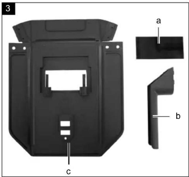
Mounting the welding mask (Fig. 3 + 4)
Fit the handle (b) to the welding mask (c).
Fit the protective glass (a) to the welding mask (c).
Then fold the three sides of the welding mask together. The two side parts are connected to the top part by two press studs.
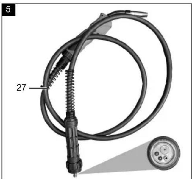
Attaching the hose assembly (Fig. 5 + 6)
Insert the hose assembly (27) into the connection (8) and screw it tight.
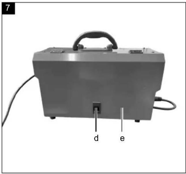
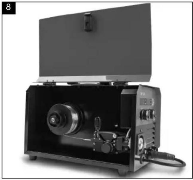
Installing the welding wire reel (Fig. 7 - 10)
- Open the cover for the wire feeding device by pushing the lock (d) upwards. Now you can see the wire feeding device and the welding wire reel (Fig. 8 - 9).
- Unlock the reel mounting (f).
- Remove all packaging from the wire reel so that it can unroll freely.
- Fit the wire reel onto the reel mounting. Ensure that the reel will unwind on the same side as the wire guide (g).
- Now press the adjustment screw (h) downwards and fold the pressing roller (j) upwards. (Fig. 9)
- Unscrew cover (i) to check the feed roller.
- The corresponding wire thickness is marked on the top side of the feed roller. If the size stipulated there does not match with the actual wire thickness, turn the feed roller or replace it if necessary.
- Now take the wire end off the edge of the reel and trim it with side cutters or wire shears. Ensure that the wire does not unroll.
- Now feed the wire through the wire guide (g) along the feed roller and into the hose assembly fitting (Fig. 9).
• Tension the pressing roller (j) again.
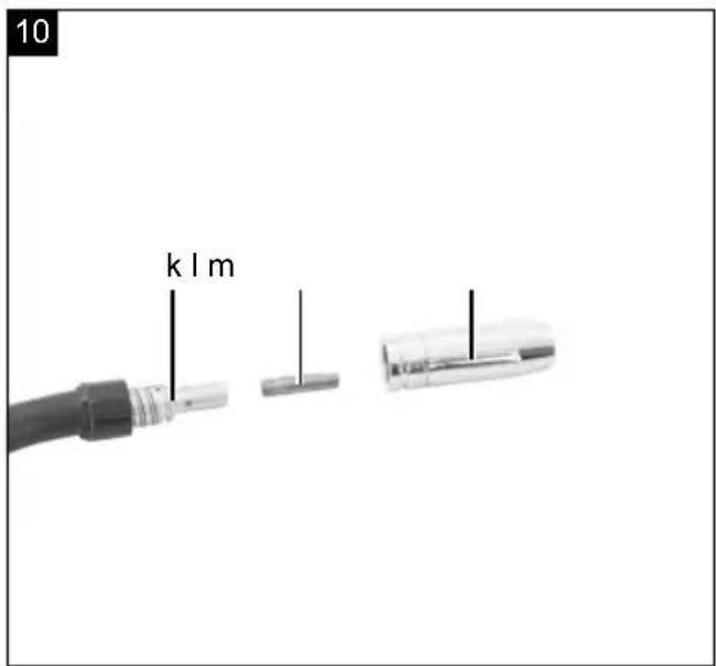
- Remove the burner nozzle (m) by simply pulling it off. Unscrew the contact tip (l) too.
- Route the hose assembly (27) as straight as possible as it runs away from the welding machine.
- Switch the welding machine on by setting the on/off switch (2) to the "ON" position.
- Now press the burner button (28) to activate the wire feed. Press the button until the wire emerges from the front of the burner. When doing so, pay attention to the feed roller. If this is slipping, re-tension the pressing roller (j) with the adjustment screw (h).
Do not touch the welding wiring during this procedure as there is a risk of injury with this!
- As soon as the wire projects ca. 5 cm from the front, release the burner button again. Then switch the machine off again and pull out the mains plug!
- Now, screw the contact tip (I) on again and ensure that the contact tip matches with the diameter of the welding wire used.
• Finally, re-attach the burner nozzle (m).
9. Before commissioning
Selection button for welding process (22)
Use the welding process selection button to select the welding process you want to use.
Selection button for welding wire diameter (26)
Use the welding wire diameter selection button to select the wire you are using.
Potentiometer for wire feed and for setting the electrical current (6)
Use the potentiometer to set the welding voltage for the MMA and LIFT TIG welding processes.
In the MIG welding process, you can use it to regulate the wire feed.
Potentiometer for welding voltage (4)
Use the potentiometer for welding voltage to adjust the welding voltage for the MIG welding process. For MMA welding, set the arc force.
10. Start up
⚠ Attention!
Always make sure the device is fully assembled before commissioning!
Note: Different welding wires are required depending on the application. Welding wires with a diameter of 0.6 – 1.0 mm can be used with this device.
Feed roller, welding nozzle and wire cross-section must always match with one another. The device is suitable for wire reels up to a maximum of 5000 g.
Use aluminium wire for welding aluminium and steel wire for welding steel and iron.
Device setting for welding with inert gas
1 Select the MIG welding function (19) on the selection button (22).
2 a. Connect the earth clamp (32) to the negative terminal (10) and lock the connector by turning it clockwise.
b. Connect the polarity change cable (11) to the positive pole (9) and lock the connector by turning it clockwise.
c. Connect the hose assembly (27) to the connector (8) and fix it by tightening the nut at the connection point.
d. Insert the appropriate welding wire and connect the gas cylinder to the connector (1) on the back of the device.
3 Connect the mains cable and activate the power supply. After connecting the earth cable, the welding process can be started.
MIG welding
- Connect the earth clamp (32) to the workpiece to be welded. Make sure that there is good electrical contact.
- Rust and paint must be removed from the workpiece at the welding point.
- Select the desired welding current to suit the welding wire diameter, the material thickness and the desired penetration depth.
- Guide the torch nozzle (30) to the place on the workpiece where welding is to be done and hold the welding shield in front of the face.
- Press the burner button (28) to feed the welding wire. Once the arc is lit, the device feeds welding wire into the weld pool.
- The optimum setting of the welding current can be determined by trial and error on a test piece. A well-adjusted electric arc creates a soft, even buzzing sound.
- If there is a rough or hard crackling sound, switch to a higher power level (increase welding current).
- If the spot is large enough, guide the burner (29) slowly along the desired edge. The distance between the burner nozzle and the workpiece should be kept as short as possible (never larger than 10 mm).
- If necessary, swing the burner nozzle slightly in order to enlarge the weld pool a little. For those with little experience, the initial difficulty lies in creating a stable electric arc. The welding current must be set correctly for this.
- The penetration depth (corresponds to the depth of the weld seam in the material) should be as deep as possible but the weld pool should not drop through the workpiece.
- If the welding current is too low, the welding wire cannot melt properly. As a result, the welding wire repeatedly dips into the weld pool right down to the workpiece.
- The slag should only be removed from the seam once it has cooled. To continue a weld on an interrupted seam:
- First remove the slag at the attachment point.
- The electric arc is struck in the weld groove, guided to the connection point, properly melted there and then continued along the weld seam
Setting suitable parameters for current and voltage for welding aluminium with aluminium wire.
Lower voltages are recommended for welding aluminium than for welding iron/steel. To set the appropriate voltage range, proceed as follows:
- Prepare the unit as described previously under "Device setting for welding with inert gas". For welding aluminium wire, select the setting "1.0/Al (23)" by pressing the selection button (26).
- Now the voltage for MIG welding can be varied within a lower voltage range suitable for aluminium welding. The welding current can be varied by turning the rotary switch for welding current adjustment (4). For welding 2 mm aluminium sheet, 14.5 volts and a current of 91 amperes can be set as guide values. The optimum welding settings should be determined on a test workpiece.
Attention! Ensure that the burner is always set down on an insulated surface after welding.
• Always switch the welding machine off and pull the mains plug out of the socket after the welding work is complete and during breaks
Creating a weld seam
Forward-pointing welding or butt welding
The burner is pushed forward. Result: The penetration depth is smaller, seam width larger, seam top bead (visible surface of the weld) flatter and the fusion fault tolerance (defect in material melting) larger.
Drag weld seam or draw welding
The torch is pulled away from the weld. Result: The penetration depth is greater, the seam width smaller, the seam top bead higher and the fusion fault tolerance smaller.
Welded joints
There are two basic types of connection in welding technology:
Butt joint (outside corner) and fillet joint (inside corner and overlap).
Butt weld joints
For butt joints up to 2 mm material thickness, the weld edges are brought completely together. For larger thicknesses, a distance of 0.5 - 4 mm should be chosen. The ideal spacing depends on the welded material (aluminium or steel), the material composition and the selected welding method.
This distance should be determined on a test piece.
Flat butt weld joints
Welds should be carried out without interruption and with sufficient penetration, so good preparation is extremely important. The quality of the resultant weld is influenced by: the current intensity, the distance between the welding edges, the inclination of the torch and the diameter of the welding wire. The steeper the torch is held in relation to the workpiece, the higher the penetration depth and vice versa.
Fillet weld joints
A fillet weld is created when the workpieces are perpendicular to each other. The seam should have the shape of a triangle with sides of equal length and a slight valley.
Overlapping weld joints
The most common preparation is the one with straight welding edges. The weld can be resolved with a normal angled weld. The two workpieces must be brought as close together as possible.
In order to anticipate or reduce deformations that can occur during material hardening, it is good to fix the workpieces with a clamping device. Avoid stiffening the welded structure to prevent fractures in the weld. These difficulties can be reduced if it is possible to rotate the workpiece so that the welding can be carried out in two opposite passes.
Wire diameter in mm x 10 = Gas flow in l/min
For a 0.8 mm wire, for example, this results in a value of approx. 8 l/min.
Machine setting for welding without inert gas
If you use flux-cored wire with integrated inert gas, there is no need to supply external inert gas.
- First connect the polarity changeover (11) with the negative pole (10). Lock the connector by turning it clockwise.
Connect the hose assembly (27) to the connector (8) and fix it by tightening the nut at the connection point. - Then connect the earth clamp (32) with the corresponding positive terminal (9) and turn the terminal clockwise to fix it.
- Insert the flux-cored wire as described under "As-sembly of the welding wire reel".
Device setting for welding with rod electrodes
1 Select the MMA welding function on the selection button (22).
2 Connect the earth cable (32) to the positive terminal (9) marked and lock the connector by turning it clockwise.
3 Next, connect the welding cable to the negative terminal (10) marked and lock the connector by turning it clockwise. NOTE! The polarity of the wires may vary! All information regarding polarisation should be available on the packaging of the electrodes supplied by the manufacturer!
4 Now the mains cable can be connected and the power supply activated. After connecting the earth cable to the welding machine, work can begin.
MMA welding
- Prepare the device as described previously under "Device setting for welding with rod electrodes".
- Put on suitable protective clothing in accordance with the specifications and prepare your workplace.
- Connect the earth clamp (32) to the workpiece.
- Clamp the electrode in the electrode holder (31).
- Switch the device on by setting the ON/OFF switch (2) to the "I" ("ON") position.
- Select "MMA" mode by pressing the selection button (22) until the indicator light next to "MMA" (20) lights up.
- Adjust the welding current with the welding current adjustment potentiometer (4) to suit the electrode used.
- Hold the protective welding mask in front of the face and start welding.
- To complete the working process, set the ON/OFF switch (2) to the "O" ("OFF") position.
| Electrode ∅ (mm) Welding current (A) | |
| 1,6 25 - 40 A | |
| 2 40 - 60 A | |
| 2,5 50 - 80 A | |
| 3,2 80 - 130 A | |
| 4,0 130 - 180 A | |
⚠ Attention!: The earth clamp (32) must not be brought into direct contact with either the electrode holder (31) or the electrode.
⚠ Attention!: Do not dab the electrode on the workpiece. It could be damaged and the ignition of the arc could be made difficult. Once the arc has ignited, try to maintain a distance from the workpiece that corresponds to the electrode diameter used. The distance should remain as constant as possible while you are welding. The electrode inclination in the working direction should be 20–30 degrees.
⚠ Attention!: Always used tongs to remove used electrodes or move hot workpieces. Note that the electrode holder must always be placed on an insulating base after welding.
The slag should only be removed from the seam once it has cooled. To continue a weld on an interrupted seam:
- First remove the slag at the connection point.
- The electric arc is struck in the weld groove, guided to the connection point, properly melted there and then continued along.
Attention!: The welding work generates heat. Therefore, the welder must be left idle for at least half an hour after use. Alternatively, let the device cool down for one hour. The device must not be packed and stored until its temperature has normalised.
⚠ Attention!: A voltage that is 10% lower than the rated input voltage of the welding machine can lead to the following consequences:
• The current of the unit decreases.
• The arc breaks off or becomes unstable.
⚠ Attention!
- The arc radiation can cause eye inflammation and skin burns.
- Spray and molten slag can cause eye injuries and burns.
- Assemble the welding shield as described under "Assembling the welding mask".
Only welding cables that are included in the scope of delivery may be used.
Choose between forward-pointing welding and draw welding. The influence of the direction of movement on the properties of the weld seam is shown below:
| Forward-pointing welding | |
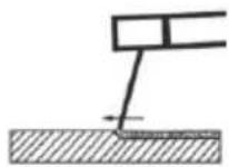 | |
| Weld penetration Smaller | |
| Weld seam width Larger | |
| Weld bead Flatter | |
| Welding seam defects Larger | |
| Draw welding | ||
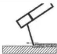 | ||
| Weld penetration Larger | ||
| Weld seam width Smaller | ||
| Weld bead Higher | ||
| Welding seam defects | Smaller | |
Note: You decide for yourself which type of welding is more suitable after you have welded a test piece.
Note: When the electrode is completely worn out, it must be replaced.
LIFT TIG welding process (hose assembly not included in the scope of delivery)
For LIFT TIG welding, please follow the instructions for your LIFT TIG torch. The LIFT TIG mode can be selected by pressing the selection button (26). To do this, select the position "LIFT TIG" (21).
11. Electrical connection
The customer's mains connection as well as the extension cable used must also comply with these regulations.
Damaged electrical connection cable
The insulation on electrical connection cables is often damaged.
This may have the following causes:
- Pressure points, where connection cables are passed through windows or doors.
- Kinks where the connection cable has been improperly fastened or routed.
- Places where the connection cables have been cut due to being driven over.
- Insulation damage due to being ripped out of the wall outlet.
- Cracks due to the insulation ageing.
Such damaged electrical connection cables must not be used and are life-threatening due to the insulation damage.
Check the electrical connection cables for damage regularly. Ensure that the connection cables are disconnected from electrical power when checking for damage.
Electrical connection cables must comply with the applicable VDE and DIN provisions. Only use connection cables with the designation H05RR-F.
The printing of the type designation on the connection cable is mandatory.
• The mains voltage must be 230 V\~
- Extension cables up to 25 m long must have a cross-section of 2.5 mm2.
Connections and repair work on the electrical equipment may only be carried out by electricians.
Please provide the following information in the event of any enquiries:
• Data of machine type plate
12. Maintenance and cleaning
Danger!
Disconnect the mains plug before carrying out any cleaning work.
Note: The welding machine must be serviced and overhauled regularly to ensure proper operation and compliance with safety requirements. Improper and incorrect operation may result in failure and damage to the device.
- Before carrying out any cleaning work on the welding device, pull the mains cable 8 out of the socket so that the device is safely disconnected from the power supply circuit.
- Clean the outside of the welding device and its accessories regularly. Remove dirt and dust using air, a cleaning rag or a brush.
Note: The following maintenance work shall be carried out only by qualified specialists.
- Current regulator, earthing device, internal wiring, the welding torch coupling device and adjustment screws should be serviced regularly. Retighten loose screws and replace rusty screws.
- Regularly check the insulation resistances of the welding device. Use the appropriate measuring device for this purpose.
- In the event of a defect or if it is necessary to replace parts of the device, please contact the appropriate specialist personnel.
The device has no further internal parts that require maintenance.
Service information
With this product, it is necessary to note that the following parts are subject to natural or usage-related wear, or that the following parts are required as consumables.
Wearing parts*: Electrode holder, earth clamp, current nozzle, burner nozzle
* may not be included in the scope of supply!
Spare parts and accessories can be obtained from our service centre. To do this, scan the QR code on the cover page.
13. Storage
Store the device and its accessories in a dark, dry and frost-free place that is inaccessible to children. The optimum storage temperature lies between 5 and 30 °C. Store the power tool in its original packaging. Cover the power tool to protect it from dust or moisture. Store the operating manual with the power tool.
14. Disposal and recycling

The device is supplied in packaging to avoid transport damages. This packaging is raw material and can thus be used again or can be reintegrated into the raw material cycle.

The device and its accessories are made of different materials, such as metals and plastics. Take defective components to special waste disposal sites. Check with your specialist dealer or municipal administration!
Old devices must not be disposed of with household waste!
This symbol indicates that this product must not be disposed of together with domestic waste in compliance with the Directive (2012/19/EU) pertaining to waste electrical and electronic equipment (WEEE). This product must be handed over at the intended collection point. This can be done, for example, by returning it when purchasing a similar product or delivering it to an authorised collection point for the recycling of old electrical and electronic devices. Improper handling of waste equipment may have negative consequences for the environment and human health due to potentially hazardous substances that are often contained in electrical and electronic equipment. By properly disposing of this product, you are also contributing to the effective use of natural resources. You can obtain information on collection points for waste equipment from your municipal administration, public waste disposal authority, an authorised body for the disposal of waste electrical and electronic equipment or your waste disposal company.
15. Troubleshooting
The following table shows fault symptoms and describes remedial measures in the event of your machine failing to work properly. If you cannot localise and rectify the problem with this, please contact your service workshop.
| Fault Possible cause Remedy | ||
| The machine will not switch on | No mains voltage | Check the socket, mains cable, cable, mains plug; have these repaired by a qualified electrician if necessary. |
| The main fuse has tripped Check the main fuse | ||
| On / off switch defective Repair by customer service department | ||
| No ignition spark | Earth clamp not connected to the device | Connect the earth clamp to the welding machine |
| Earth clamp not fitted on the workpiece | Fit the earth clamp on the workpiece | |
| Machine cannot be operated even though the indicator lamp for operation is on | Hose assembly loose Tighten the hose assembly | |
| Inadequate connection between earth clamp and workpiece | Make sure that the area where the earth clamp is attached is clean, bare metal, free from dirt, paint and oil. | |
| Machine cannot be operated because overheating indicator light is on | Machine is overheated Allow the machine to cool down | |
| Duty cycle or current is too high | Reduce the duty cycle or the current setting | |
| Irregular arc / welding power | Loose connections Check the connections and clean them | |
| Wrong polarity Connect with correct polarity | ||
| Workpiece is painted or dirty | Clean the workpiece thoroughly until the surface is bare metal and free of dirt and paint. | |
Günzburger Straße 69
D-89335 Ichenhausen
Cher client,
Günzburger Straße 69
89335 Ichenhausen, Germania
Egregio cliente,
Günzburger Straße 69
D-89335 Ichenhausen
Geachte klant,
- Ontgrendel de rollagers (f).
Overlappingslasnaadverbindingen
Draaddiameter in mm x 10 = gasstroom in l/min
Günzburger Straße 69
Günzburger Straße 69
CE Declaration of Conformity
Standard references:
EN IEC 60974-1:2008/A1:2019; EN 60974-10:2014/A1:2015
This declaration of conformity is issued under the sole responsibility of the manufacturer.
The object of the declaration described above fulfils the regulations of the directive 2011/65/EU of the European Parliament and Council from 8th June 2011, on the restriction of the use of certain hazardous substances in electrical and electronic equipment.
Subject to change without notice
Documents registrar: Viktor Härtl
Günzburger Str. 69, D-89335 Ichenhausen
Garantie DE
Apparent defects must be notified within 8 days from the receipt of the goods. Otherwise, the buyer's rights of claim due to such defects are invalidated. We guarantee for our machines in case of proper treatment for the time of the statutory warranty period from delivery in such a way that we replace any machine part free of charge which provably becomes unusable due to faulty material or defects of fabrication within such period of time. With respect to parts not manufactured by us we only warrant insofar as we are entitled to warranty claims against the upstream suppliers. The costs for the installation of the new parts shall be borne by the buyer. The cancellation of sale or the reduction of purchase price as well as any other claims for damages shall be excluded.
Garantie FR


- WSE5000-Multi
- Verehrter Kunde
- Explanation of the symbols on the device
- Table of contents: Page:
- Introduction
- Manufacturer:
- Dear Customer
- Note:
- Please consider:
- Device description (Fig. 1)
- Scope of delivery
- Proper use
- General safety information
- Always observe
- ATTENTION!
- Note!
- Sources of danger when arc welding
- ⚠ Attention
- Danger due to electric shock
- Danger due to welding fumes
- Danger due to welding sparks
- Safety instructions specific to welding masks
- Environment with increased electrical hazards
- Welding in confined spaces
- Summation of open circuit voltages
- Use of shoulder slings
- Protective clothing
- Protection from rays and burns
- EMC equipment classification
- In order to reduce possible interference radiation, it is recommended:
- General safety measures
- Technical data
- Unpacking
- WARNING!
- Assembly
- Mounting the welding mask (Fig. 3 + 4)
- Attaching the hose assembly (Fig. 5 + 6)
- Installing the welding wire reel (Fig. 7 - 10)
- Before commissioning
- Selection button for welding process (22)
- Selection button for welding wire diameter (26)
- Potentiometer for wire feed and for setting the electrical current (6)
- Potentiometer for welding voltage (4)
- Start up
- ⚠ Attention!
- Always make sure the device is fully assembled before commissioning!
- Device setting for welding with inert gas
- MIG welding
- Setting suitable parameters for current and voltage for welding aluminium with aluminium wire.
- Creating a weld seam
- Forward-pointing welding or butt welding
- Drag weld seam or draw welding
- Welded joints
- Butt weld joints
- Flat butt weld joints
- Fillet weld joints
- Overlapping weld joints
- Machine setting for welding without inert gas
- Device setting for welding with rod electrodes
- MMA welding
- LIFT TIG welding process (hose assembly not included in the scope of delivery)
- Electrical connection
- Damaged electrical connection cable
- Maintenance and cleaning
- Danger!
- Service information
- Storage
- Disposal and recycling
- Old devices must not be disposed of with household waste!
- Troubleshooting
- Cher client,
- Egregio cliente,
- Geachte klant,
- Overlappingslasnaadverbindingen
- CE Declaration of Conformity
- Standard references:
- Garantie DE
- Garantie FR
Brand : SCHEPPACH
Model : WSE5000-Multi
Category : Welding machine