
BLFS420 - Wall mount SANUS - Free user manual and instructions
Find the device manual for free BLFS420 SANUS in PDF.

| Product type | Swiveling wall mount |
| Brand | Sanus |
| Model | BLFS420 |
| Maximum load capacity | 56.6 kg (125 lb) |
| Material | Steel |
| VESA compatibility | Universal (up to 600x400 mm) |
| Compatible wall types | Wood studs, solid concrete, concrete blocks |
| Tilt | Adjustable (+5°/-15°) |
| Rotation/Swivel | Not specified (manually adjustable) |
| Lateral shift | Adjustable (on wood studs only) |
| Cable management | Integrated |
| Wall plate dimensions (approx.) | 50 x 25 cm |
| Depth (arm extended) | Approximately 60 cm |
| Mount weight | Approximately 5 kg |
| Care and cleaning | Clean with a soft, dry cloth. Do not use abrasive products. |
| Safety | Do not exceed the maximum load. Installation on a solid wall is mandatory. |
| Spare parts | Available on request from Sanus customer service. |
| Repairability | Repairable by a qualified professional. |
| Warranty | Manufacturer's warranty (see manual) |
Frequently Asked Questions - BLFS420 SANUS
User questions about BLFS420 SANUS
0 question about this device. Answer the ones you know or ask your own.
Ask a new question about this device
Download the instructions for your Wall mount in PDF format for free! Find your manual BLFS420 - SANUS and take your electronic device back in hand. On this page are published all the documents necessary for the use of your device. BLFS420 by SANUS.
USER MANUAL BLFS420 SANUS
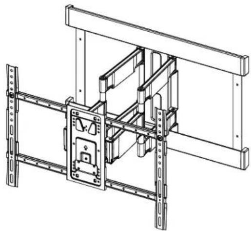
natural_image
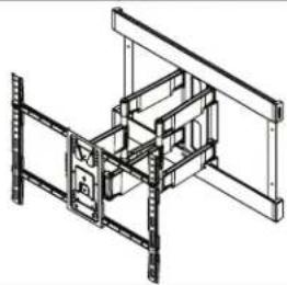
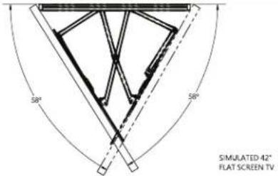
Technical line drawing of a mechanical assembly with mounting brackets and a central lock mechanism (no text or symbols)BLFS420-B3
INSTRUCTION MANUAL
natural_image
Person holding a digital play button with a white play symbol on a table (no text or symbols visible)Want to watch a video that shows how easy this is?

Get it right the first time. HeightFinder™ shows you where to drill.

natural_image
Office workers in a trading environment, one person using a headset (no visible text or symbols)Our live US-based install experts are standing by to help.

Watch it now at: SANUS.com/3115


Use it now: SANUS.com/1172


Call us at: US: +1 (800) 359-5520
IMPORTANT SAFETY INSTRUCTIONS
- PLEASE READ MANUAL PRIOR TO USE - SAVE THESE INSTRUCTIONS

CAUTION: Avoid potential personal injuries and property damage!
- This product is designed ONLY to be installed into wood studs, solid concrete or concrete bloc
— DO NOT INSTALL INTO DRYWALL ALONE — DRYWALL ALONE WILL NOT HOLD THE WEIGHT OF YOUR TV
• This product is designed for INDOOR USE ONLY
● The wall must be capable of supporting five times the weight of the TV and mount combined
- Do not use this product for any purpose not explicitly specified by manufacturer
● Manufacturer is not responsible for damage or injury caused by incorrect assembly or use
Please read through these instructions completely to be sure you're comfortable with this easy install process.
Check your TV owner's manual to see if there are any special requirements for mounting your TV.
If you do not understand these instructions or have doubts about the safety of the installation, assembly or use of this product, contact Customer Service.
TV Weight Limit
(including accessories)
DO NOT EXCEED
If your TV (plus accessories) weighs MORE, this mount is NOT compatible.
Visit SANUS.com or call customer service to find a compatible mount.
Wall Construction
ONLY install on these acceptable wall types.

Unsure
Call Customer Service
1-800-359-5520

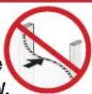
CAUTION:
DO NOT install in drywall alone
Drywall alone will NOT hold the weight of your TV.
wood studs Solid concrete
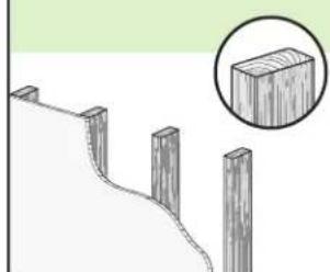
natural_image
Diagram showing a wooden fence with four posts and a magnified inset of a rectangular block (no text or symbols)ACCEPTABLE
or
concrete block
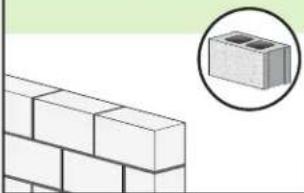
natural_image
Illustration of a brick wall with a magnified inset showing a small rectangular block (no text or symbols)Concrete anchors Required (NOT INCLUDED)
Call Customer Service
1-800-359-5520
Tools Needed
Tape Measure
Pencil Level Tape

Screwdriver
Electric Drill
Socket Wrench
Wood Stud Install
Stud Finder
Awl

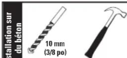
Drill Bit
Drill Bit
Hammer
Dimensions
TV INTERFACE
![3.94in MIN VESA [100mm] 28.62in MAX VESA [600mm] 17.72in MAX VESA [450mm] 3.94in MIN VESA [100mm]](/content/2026/04/668198/images/e0ba38889c058e36d2da714a3ea00930965c1cdef90d79d5a2046521578830e2.jpg)
3-D
natural_image
Isometric line drawing of a structural framework with beams and supports (no text or symbols)WALL PLATE
![14.00m [406.4mm] 24.00m [609.6mm] 28.57m [725.6mm] 15.30m [388.5mm] 17.80m [452.2mm]](/content/2026/04/668198/images/4d5ff0344f79a6ff8eb63c157eb116f20e311a8dc130b31e8be8c904186ccc8a.jpg)
TOP VIEW - EXTENDED
SIDE VIEW - EXTENDED
![10° UP TILT 20.26m [513.1mm] 10° DOWN TILT](/content/2026/04/668198/images/43c87eb2bb4baa4ecd7fee7b0c2c39647888a6485bc51473e70037be1d2ab40c.jpg)
FULLY ASSEMBLED MOUNT
![28.57m [725.6mm] 7.5m [191mm] CENTER OFFSET 18.95m [482.2mm]](/content/2026/04/668198/images/26286a9c8f340e0fb3df3119fb6f74a693ac88c200be8934f370326263133b59.jpg)
FRONT VIEW - LATERAL SHIFT
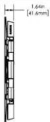
![9.06m [230mm] 8.12m [206.4mm]](/content/2026/04/668198/images/0cf25161820127b3b9e1b223f67ca3e69948e3c0b30513252a362777c9858134.jpg)
SIDE VIEW RETRACTED
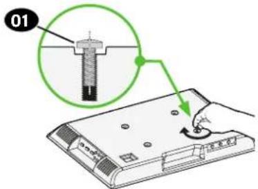
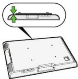
BEFORE YOU BEGIN
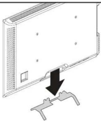
Remove the stand
from your TV — if attached.
natural_image
Diagram showing a device with a black arrow pointing to a mechanical component (no text or symbols present)Install any accessories
you may have purchased, if they require TV removal prior to assembly. The TV is removable for future accessory purchases.
natural_image
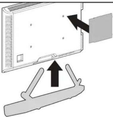
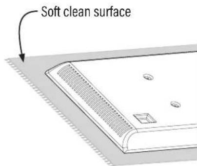
Diagram showing a device with an arrow pointing to a component, no text or symbols presentProtect the face
of your TV when laying it down for installation.
Supplied Parts and Hardware

WARNING: This product contains small items that could be a choking hazard if swallowed. Before starting assembly, verify all parts are included and undamaged. If any parts are missing or damaged, do return the damaged item to your dealer; contact Customer Service. Never use damaged parts!

NOTE: Not all hardware included will be used.
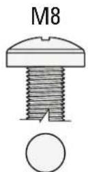
![STEP 1 01 TV Screws (qty. 4 each) [Only one size fits your TV] M6 M6 x 12mm M6 x 25mm M6 x 35mm M8 M8 x 16mm M8 x 25mm M8 x 35mm 02 Washers (qty. 4) M6/M8 03 Spacers (qty. 4 each) 2.5mm 5mm 04 TV Bracket Vertical (qty. 2) 05 TV Bracket Horizontal (qty. 1) 06 10-32 x 5/16 in. TV Interface Assembly (qty. 4)](/content/2026/04/668198/images/85bda74225fa4330c6fba2175464055ca9ba5b94e3183d57332786b0ecfa1f99.jpg)
STEP 1 Attach TV Brackets to TV
Only one screw size fits your TV.
NOTE: If your TV included inset spacers or adapters, use them UNDER the mount hardware.
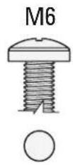
1.2 Select TV Screw Length and Spacers1.1 Select TV Screw Diameter
A
NO SPACER SPACER NEEDED
B
- Flat Back TV
[TV brackets lay flat on your TV]
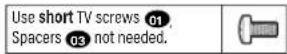
- Flat Back TV with extra space needed [for deep inset holes or cable interference]
- Rounded or Irregular Back TV [TV brackets NOT resting flat on your TV]
natural_image
Diagram of a device with a green arrow pointing to a component, showing no text or symbols.Use long TV screws 01 and spacers 03 to create extra space between the TV and TV bracket.
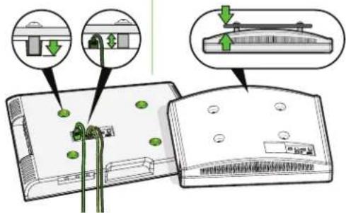
CAUTION: Verify adequate thread engagement with your screw 01, washer 02, spacer 03 combination AND TV bracket 04. — Too short will not hold your TV. — Too long will damage your TV.
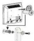
1.3 Attach TV Brackets to Your TV
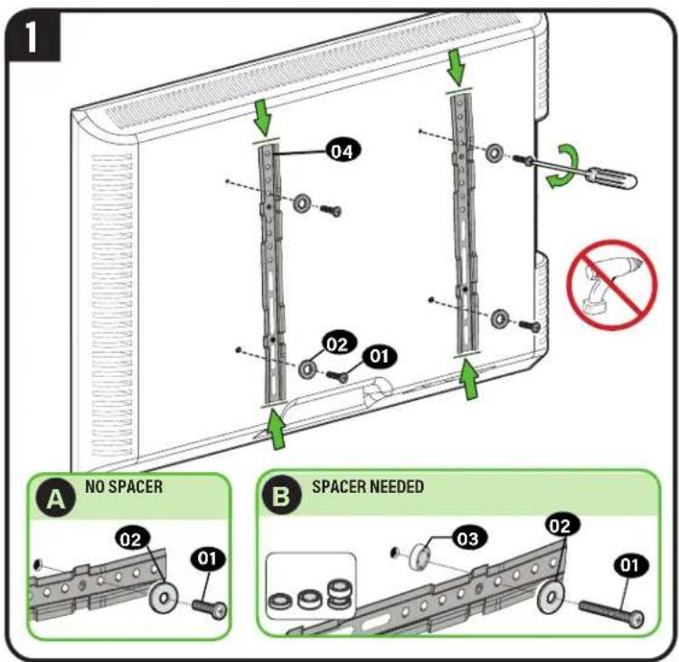
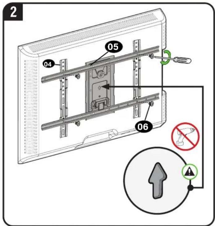
CAUTION: Avoid potential personal injuries and property damage! DO NOT use power tools for this step. Tighten the screws 06 only enough to secure the TV brackets to the TV.
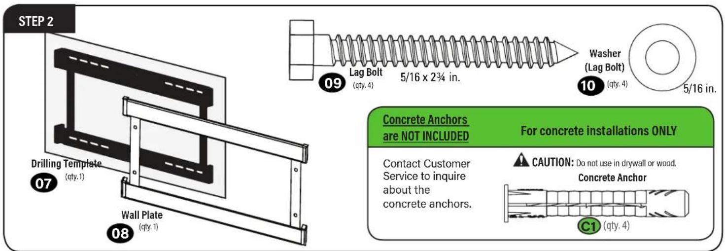
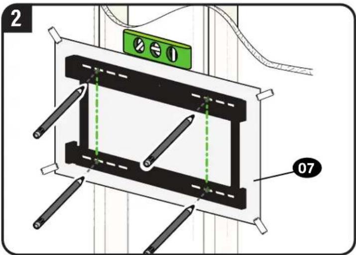
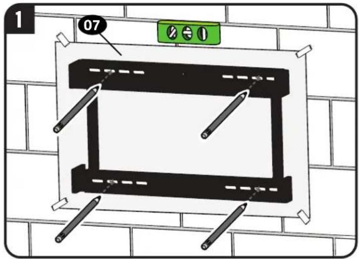
STEP 2A Attach Wall Plate
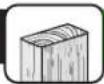
Wood Stud Installation
AUTION: Avoid potential personal injury or property damage!
● Drywall covering the wall must not exceed 5/8 in. (16 mm)
- Minimum wood stud size: nominal 2 x 4 in. (51 x 102 mm) actual 1 12 × 3 12 in. (38 x 89 mm)
• Minimum spacing between studs: 16 in. (406mm)
• Stud center must be verified
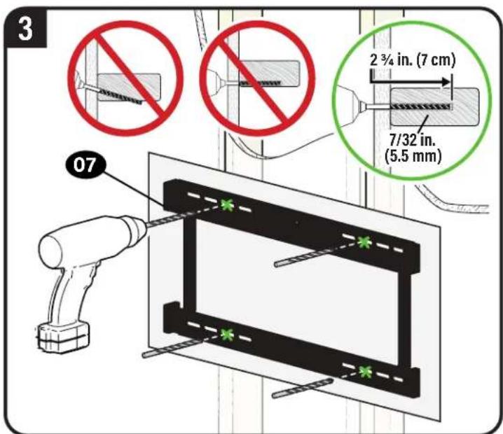
IMPORTANT: Be sure to drill into the center of the stud.
IMPORTANT: Pilot holes must be drilled to a depth of 2 34 in. (7 cm), using a 7/32 in. (5.5 mm) diameter drill bit.
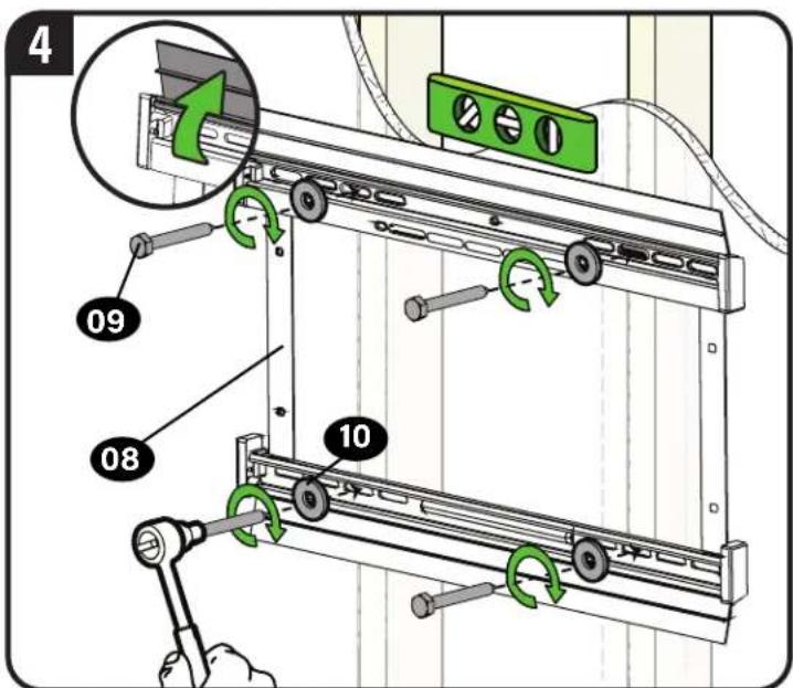
CAUTION: Avoid potential personal injury or property damage! Improper use could reduce the holding power of the lag bolt 09.
Tighten the lag bolts 09 and lag washers 10 only until they are pulled FIRMLY against the wall plate 08.
DO NOT over-tighten the lag bolts 09. Go to STEP 3 on PAGE 8.
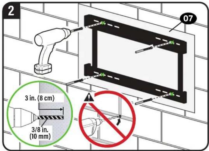
STEP 2B Attach Wall Plate
Solid Concrete or Concrete Block Installation
AUTION: Avoid potential personal injury or property damage!
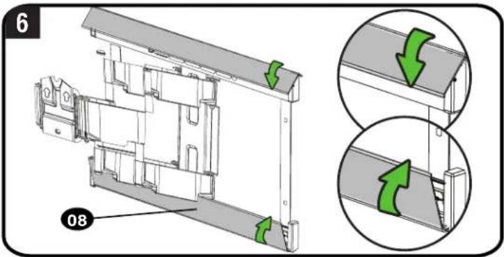
- Mount wall plate 08 directly onto concrete surface (no wall covering)
• Minimum solid concrete thickness: 8 in. (203 mm)
• Minimum concrete block size: 8 x 8 x 16 in. (203 x 203 x 406 mm)
• Minimum spacing between lag bolts is 16 in. - For concrete applications, arm assembly 11 (STEP 3) must remain centered in wall plate 08. Keep this in mind when selecting wall plate location
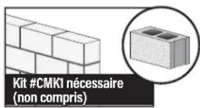
Concrete Anchors are not included
Contact Customer Service at 1-800-359-5520 to inquire about the concrete anchors.
CAUTION: Never drill into the mortar between blocks.
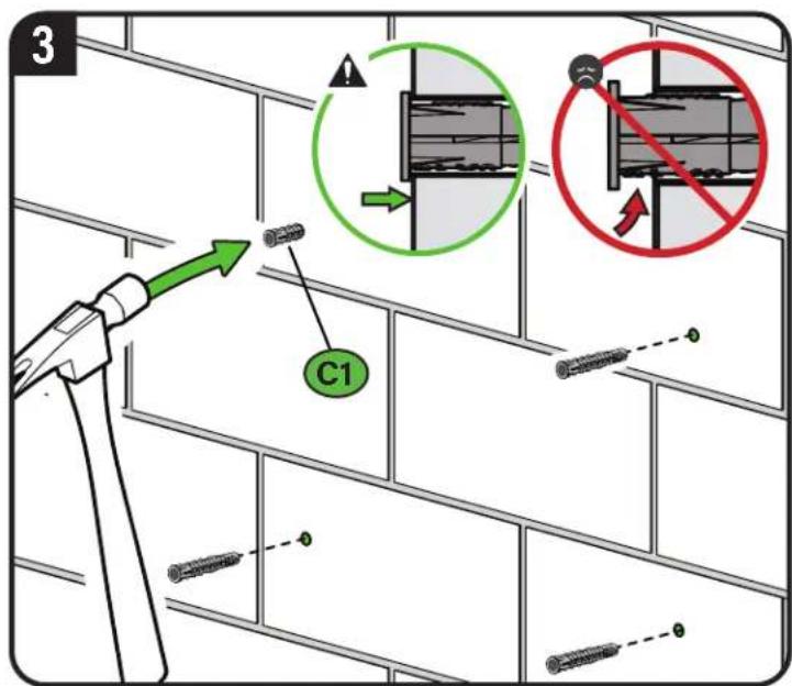
CAUTION: Be sure the anchors C1 are seated flush with the concrete surface.
Concrete achors (Fischer UX10 x 60R) C1 available through Customer Service.
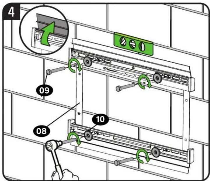
CAUTION: Avoid potential personal injury or property damage! Improper use could reduce the holding power of the lag bolt 09. Tighten the lag bolts 09 and lag washers 10 only until they are pulled FIRMLY against the wall plate 08. DO NOT over-tighten the lag bolts 09.
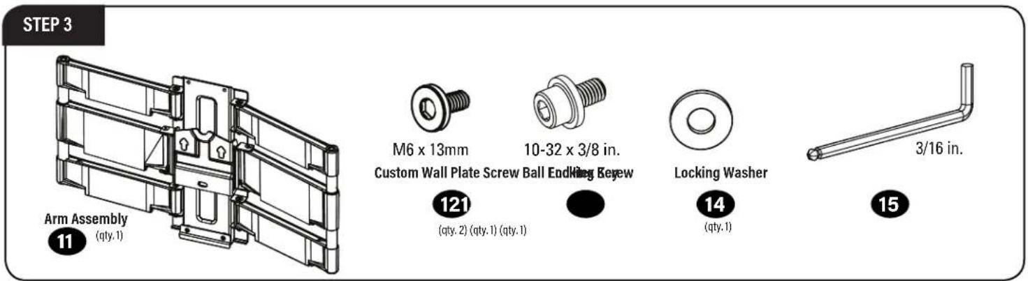
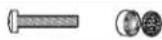
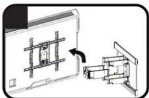
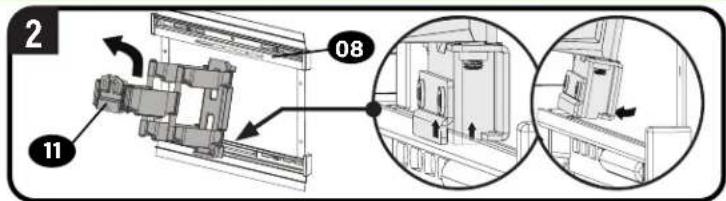
STEP 3 Hang TV onto Wall Plate
3.1 Attach Arm Assembly to Wall Plate

HEAVY! You may need assistance with this step.
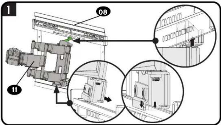
2 AUPTION: Avoid potential personal injury or property damage!
For CONCRETE APPLICATIONS:
The arm assembly 11 MUST remain centered in wall plate 08.
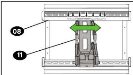
NOTE: For WOOD STUD APPLICATIONS, the arm assembly 11 can be slid anywhere along wall plate 08 for optimal positioning of your TV.
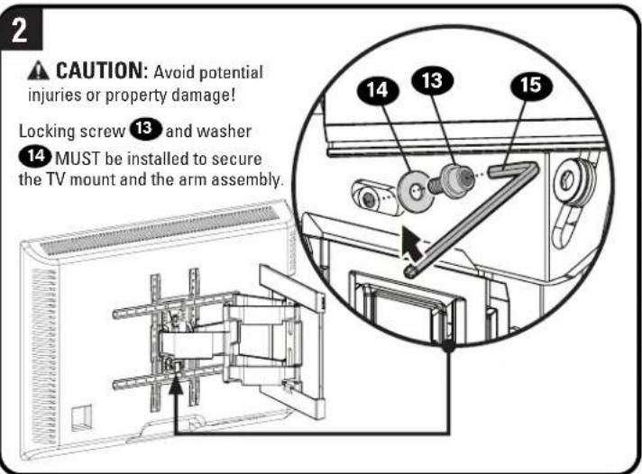
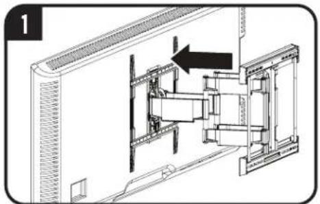
3.2 Attach TV to Arm Assembly

HEAVY! You may need assistance with this step.
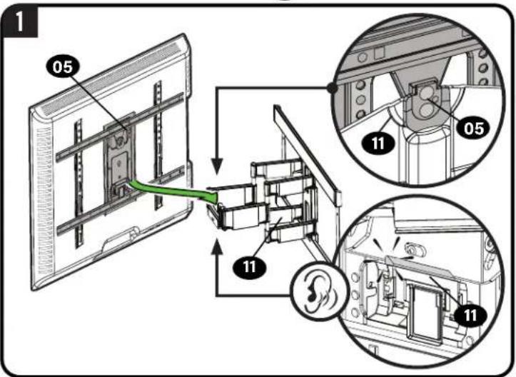
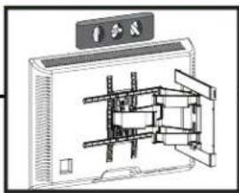
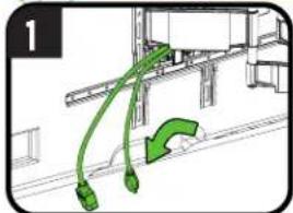
Manage Cables
- IMPORTANT: Fully extend arm assembly 11 to ensure enough slack in cables.
- Route your cables through the arm assembly 11 as shown.
natural_image
Technical diagram of a mechanical assembly with an arrow indicating direction (no text or symbols present)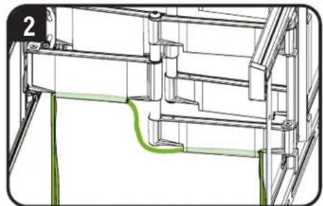
natural_image
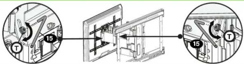
Technical line drawing of a structural frame with green highlighted section (no text or symbols)TV Adjustments

TILT ADJUSTMENT
Your TV should adjust easily when moved, then stay in place. If your TV is too loose or too tight use the hex key 15 for additional tightening of the right and left tilt tension screws T.

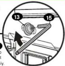
LEVEL ADJUSTMENT
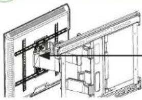
natural_image
Technical line drawing of a mechanical assembly with no visible text or symbols- Loosen security screw 13
- Level TV.
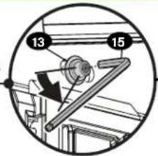
natural_image
Technical line drawing of a mechanical device with internal components and mounting bracket (no text or symbols)- Retighten security screw 13

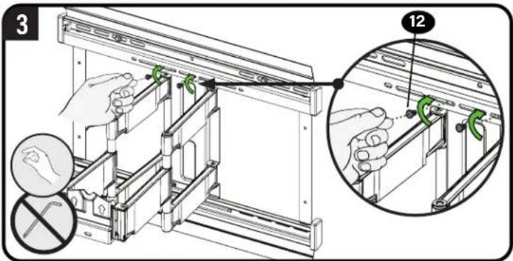
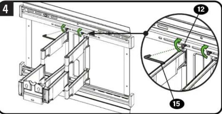
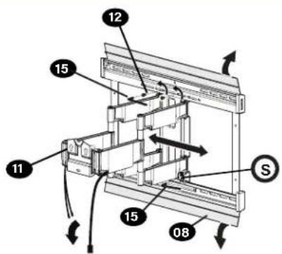
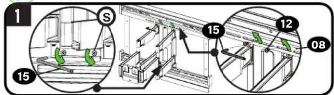
LATERAL SHIFT

HEAVY! You may need assistance with this step.
CAUTION: Avoid potential injuries or property damage!
Do NOT adjust the arm position from center for concrete applications. Arm 11 MUST remain centered in wall plate 08 for all concrete applications!
- Remove your TV (PAGE 9).
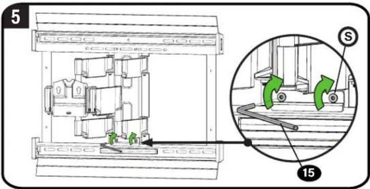
- Open the cover plates, remove two screws 12, and loosen screws at bottom of arm 5 to release arm assembly 11.
- Reposition the arm assembly 11 on the wall plate (STEP 3.1).
- Reattach the two screws 12 (STEP 3.1), tigthen the screws at the bottom of arm S, and close the cover plates.
- Hang your TV onto the arm assembly 11 following STEP 3.2.
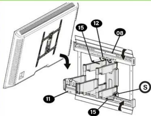

REMOVING THE TV

HEAVY! You may need assistance with this step.
natural_image
Diagram showing green curved lines and arrows indicating motion or flow, no text or symbols present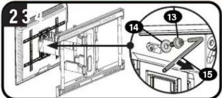

natural_image
Diagram showing a mechanical assembly with a bracket and housing, no text or symbols present
REMOVING THE ARM
FRANÇAIS
INFORMATIONS IMPORTANTES CONCERNANT LA SÉCURITÉ
- CONSERVEZ CES INSTRUCTIONS - VEUILLEZ LIRE ATTENTIVEMENT LE MANUEL AVANT D'UTILISER CE PRODUIT
1
m = 311
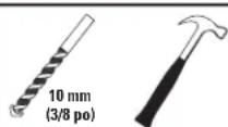
Foret pour
beton
[Non-Text]
Marteau
Thank you for choosing SANUS Elite!
Please take a moment to let us know how we did:

Call us: 1-800-359-5520

Email us: info@sanus.com

Leave a review: SANUS.com
Legrand AV Inc. and its affiliated corporations and subsidiaries (collectively, "Legrand"), intend to make this manual accurate and complete. However, Legrand makes no claim that the information contained herein covers all details, conditions, or variations. Nor does it provide for every possible contingency in connection with the installation or use of this product. The information contained in this document is subject to change without notice or obligation of any kind. Legrand makes no representation of warranty, expressed or implied, regarding the information contained herein. Legrand assumes no responsibility for accuracy, completeness or sufficiency of the information contained in this document.
©2024 Legrand AV Inc. All rights reserved. SANUS is a brand of Legrand. SANUS Elite and the SANUS Elite logo are registered trademarks of Legrand.