FTXK60AV1BS - Air Conditioning DAIKIN - Free user manual and instructions
Find the device manual for free FTXK60AV1BS DAIKIN in PDF.


User questions about FTXK60AV1BS DAIKIN
0 question about this device. Answer the ones you know or ask your own.
Ask a new question about this device
Download the instructions for your Air Conditioning in PDF format for free! Find your manual FTXK60AV1BS - DAIKIN and take your electronic device back in hand. On this page are published all the documents necessary for the use of your device. FTXK60AV1BS by DAIKIN.
USER MANUAL FTXK60AV1BS DAIKIN
Operating Manual Handset Wireless
English
text_image
Remote buttoning if the conditioner is not in use for a long period of time. Use 2 dAb- TBA button. ② ③ ① ② 0:OPENREMOTE CONTROLLER LOSS PREVENTION WITH BALL CHAIN (OPTIONAL) / PRÉVENTION CONTRE LA PERTE DE LA TÉLÉCOMMANDE PAR CHAÎNETTE À BOULES (FACULTATIF) / DIE FERNBEDIENUNG IST DURCH EINE KUGELKETTE VOR VERLUST GESICHERT (OPTIONAL) / PREVENZIONE PERDITA TELECOMANDO CON CATENA A SFERA (OPZIONALE) / PREVENCIÓN DE PÉRDIDA DEL CONTROL REMOTO CON CADENA DE BOLAS (OPCIONAL) / ПРЕДОТВРАЩЕНИЕ ПОТЕРИ ПДУ С ПОМОЩЬЮ ШАРИКОВОЙ ЦЕПИ (ДОПОЛНИТЕЛЬНОЕ ОБОРУДОВАНИЕ) / ZÎNCÎRLE UZAKTAN KUMANDANIN KAYBOLMASININ ÖNLENMESI (İSTEĞE BAĞLI)

text_image
Remote controller Télécommande Fernbedienung Telecomando Control Remoto Пульт дистанционного управления Uzaktan kumanda Ball chain (350mm) Chaînette à boules (350 mm) Kugelkette (350mm) Catena a sfera (350mm) Cadena de bolas (350mm) Шариковая цепь (350 mm) Zincir (350mm) Screw Vis Schraube Vite Tornillo Винт Vida Wall attachment screw Vis de fixation murale Schraube für Wandbefestigung Vite fissaggio a parete Tornillo de instalación en pared Винт настенного крепления Duvar bağlanti vidası Holder Support Soutien de détenteur Houder ondersteuning Supporto Holder Apoyo Holder Поддержка держатель Tutucu desteğiInstallation
- Match the ring at the end of the ball chain with the screw hole on the back of the remote controller and secure it with the screw.
- Attach the holder and the ball chain as above at the position where signals from the remote controller can be received easily.
- Pass the ball chain through the back of the holder and match the ring at the end of the ball chain to the upper hole of the holder. Fix the holder to the wall by putting through 2 screws across it.
Installation
2) Quantity: 2 pieces
Disposal Requirements

The batteries supplied with the controller are marked with this symbol.
This means that the batteries shall not be mixed with unsorted household waste.
If a chemical symbol is printed beneath the symbol, this chemical symbol means that the battery contains a heavy metal above a certain concentration.
Possible chemical symbols are:
■ Pb: lead (>0.004%)
Waste batteries must be treated at a specialized treatment facility for re-use. By ensuring correct disposal, you will help to prevent potential negative consequences for the environment and human health. Please contact your local authority for more information.
Pile
1) Type: AAA.R03
1. Transmission source
- The source where the signal will be transmitted.
2. Signal transmission indication
- Blink to confirm that the last setting has been transmitted to the unit.
3. "ON/OFF" Button
- Press once to start the air conditioner unit.
- Press again to stop the unit.
4. Fan speed selection
- Pressing button continuously will toggle the fan speed in the following order:
Low → Med → High → Auto →
- Stop pressing when the desired fan speed appears on the display screen.
5. Operation mode
- Press the MODE button to select the type of operating mode.
- For cooling only unit, the available modes are: COOL (*), DRY (☑) and FAN (♣).
- For heat pump unit, the available modes are: AUTO (☐), COOL (✗), DRY (☐), FAN (✗) and HEAT (✗).
- The AUTO (A) mode is unavailable for chilled water system except 4-pipe system.
6. Automatic air swing
- Press the SWINGn to activate the automatic air swing function.
- To distribute the air to a specific direction, press the SWING ⏻ button and wait until the louver move to the desired direction and press the button once again.
Swing mode selection method (model dependent)
- Press SWING (☐) button for 4 seconds to enter field setting mode. While in field setting mode, it will only show SWING MODE (☐).
- Press temperature ▲ and ▼ button to select SWING MODE (≡) rotation from Swing Mode 1 to Swing Mode 3.
- There are 3 different SWING MODE, which are:

Swing mode 1 Swing mode 2 Swing mode 3
SWING MODE will not activate unless SWING is activated.
Swing is indicated by the logo:

- If no mode changes within 4 seconds, unit will operate according to the selected SWING MODE (→).
7. Powerful & Powerful+ function
- Press ^+ for fast cooling or heating operation.
• Fan speed turn to maximum speed.
- Press again for smart cooling or heating operation.
- Fan speed turn to maximum speed and louver will be adjusted as according to the judgement of sense function.
- Press again to deactivate the function.
• Available under HEAT and COOL modes only.
- Any change of fan speed will deactivate this function.
8. OFF timer setting
- Press the OFF TIMER button will activate the off timer function.
- Set the desired off time by pressing the OFF TIMER button continuously.
- Press the CANCEL button to cancel the off timer setting.
9. Quiet function (model dependent)
• Press for quiet operation.
• Fan speed turn to minimum speed.
- Press again to deactivate the function.
• Available under HEAT and COOL modes only.
- Any change of fan speed will deactivate this function.
10. Clock time setting
- Press and hold CLOCK button to set the clock time.
11. ON timer setting
- Press the ON TIMER button will activate the on timer function.
- Set the desired on time by pressing the ON TIMER button continuously. If the timer is set to 7.30am, the air conditioner will turn on at 7.30am sharp.
- Press the CANCEL button to cancel the on timer setting.
12. Sleep mode setting
- Press ⚙ bheton will activate the sleep mode function.
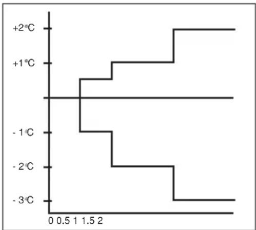
- This is an energy saving option. When the unit is operating under cooling mode,
the set temperature is increased by 0.5^ C after the first half an hour, another 0.5^ C after the second half an hour and 1^ C after the following 1 hour.
- When the unit is operating under heating mode, the set temperature is decreased by 1°C after the first half an hour, another 1°C after the second half an hour and 1°C after the following 1 hour.
- This function is available under COOL, HEAT and AUTO mode.
line
| Time (s) | Temperature (°C) | | :--- | :--- | | 0.5 | -3 | | 1.5 | -2 | | 2 | -1 | | 3 | -1 | | 4 | +1 | | 5 | +2 | The chart displays a step function of temperature over time. The x-axis represents time in seconds (0 to 2 s). The y-axis represents temperature in degrees Celsius (from -3°C to +2°C). There is no additional data series or labels provided in the image.13. Temperature setting
- To set the desired room temperature, press the ▲ or ▼ button to increase or decrease the set temperature.
- The temperature setting range is from 16°C to 30°C (Optional setting 20°C to 30°C).
- Press both buttons ▲ and ▼simultaneously to toggle from °C to °F setting.
14. ECO+ function

• Press eco-friendly mode cooling or heating operation.
- Set temperature automatically adjust to eco-friendly level.
- Press again to deactivate the function.
• Available under HEAT and COOL modes only.
15. LED function

• Presturn on/off the light on ceiling cassette unit.
- Continuous press for 5 seconds to turn on/off the LED display on wall-mounted unit.
• Available under HEAT, COOL, DRY, FAN and AUTO modes only.
16. Sense function

• Press intelligent eco cooling, heating or dry mode operation.
- Temperature display on wireless handset will automatically display 24°C as the eco-friendly level.
- Press again to deactivate the function.
• Available under HEAT, COOL and DRY mode.
FAULT DIAGNOSIS (For Inverter only)
FAULT DIAGNOSIS BY REMOTE CONTROLLER
The temperature display sections indicate corresponding codes.
- When the ON TIMER CANCEL button or OFF TIMER CANCEL button is held down for 5 seconds, a “” indication flashes on the temperature display section.
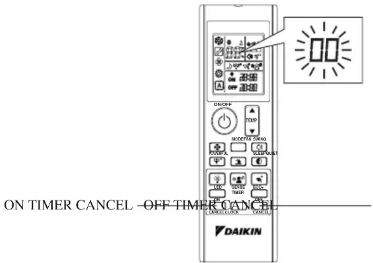
- Press the ON TIMER CANCEL button or OFF TIMER CANCEL button repeatedly until a continuous beep is produced.
- The code indication changes as shown below, and notifies with a long beep.
| ERROR CODE MEANING | |
| 00 NORMAL | |
| A1 INDOOR PCB ERROR | |
| A3 DRAIN PUMP ABNORMAL | |
| A5 ANTIFREEZE (COOLING)/HEAT EXCHANGER OVERHEAT (HEATING) | |
| A6 INDOOR FAN MOTOR ABNORMAL | |
| AH ELECTRICAL AIR CLEANER ABNORMAL | |
| C4 INDOOR HEAT EXCHANGER (1) THERMISTOR SHORT/OPEN | |
| C5 INDOOR HEAT EXCHANGER (2) THERMISTOR SHORT/OPEN | |
| C7 LOUVER LIMIT SWITCH ERROR | |
| C9 INDOOR ROOM THERMISTOR SHORT/OPEN | |
| E1 OUTDOOR PCB ERROR | |
| E3 HIGH PRESSURE PROTECTION | |
| E4 LOW PRESSURE PROTECTION | |
| E5 COMPRESSOR MOTOR LOCK/COMPRESSOR OVERLOADED | |
| E6 COMPRESSOR START-UP ERROR | |
| E7 OUTDOOR DC FAN MOTOR LOCK | |
| E8 AC INPUT OVER CURRENT | |
| E9 EXV ERROR | |
| EA 4 WAY VALVE ERROR | |
| F3 DISCHARGE PIPE OVERHEAT | |
| F6 HEAT EXCHANGER OVERHEAT | |
| HO COMPRESSOR SENSOR SYSTEM ERROR | |
| H3 HIGH PRESSURE SWITCH ERROR | |
| H6 COMPRESSOR FEEDBACK DETECTION ERROR | |
| H7 FAN MOTOR OVERLOADED/OVERCURRENT/SENSOR ABNORMAL | |
| H8 AC CURRENT SENSOR ERROR | |
| ERROR CODE | MEANING |
| H9 OUTDOOR AIR THERMISTOR SHORT/OPEN | |
| J1 PRESSURE SENSOR ERROR | |
| J3 COMPRESSOR DISCHARGE PIPE THERMISTOR SHORT/OPEN/MISPLACED | |
| J5 SUCTION PIPE THERMISTOR SHORT/OPEN | |
| J6 OUTDOOR HEAT EXCHANGER THERMISTOR SHORT/OPEN | |
| J7 SUBCOOLING HEAT EXCHANGER THERMISTOR SHORT/OPEN | |
| J8 LIQUID PIPE THERMISTOR SHORT/OPEN | |
| J9 GAS PIPE THERMISTOR SHORT/OPEN | |
| L1 INVERTER OUTDOOR PCB ERROR | |
| L3 OUTDOOR CONTROL BOX OVERHEAT | |
| L4 HEAT SINK OVERHEAT | |
| L5 IPM ERROR/IGBT ERROR | |
| L8 INVERTER COMPRESSOR OVERCURRENT | |
| L9 COMPRESSOR OVERCURRENT PREVENTION | |
| LC COMMUNICATION ERROR (OUTDOOR CONTROL PCB AND INVERTER PCB) | |
| P1 OPEN PHASE OR VOLTAGE UNBALANCE | |
| P4 HEAT SINK THERMISTOR SHORT/OPEN | |
| PJ CAPACITY SETTING ERROR | |
| U0 INSUFFICIENT GAS | |
| U2 DC VOLTAGE OUT OF RANGE | |
| U4 COMMUNICATION ERROR | |
| U7 COMMUNICATION ERROR (OUTDOOR CONTROL PCB AND IPM PCB) | |
| UA INSTALLATION ERROR | |
| UF | PIPING & WIRING INSTALLATION MISMATCH/WRONG WIRING/INSUFFICIENT GAS |
| UH ANTIFREEZE (OTHER ROOMS) | |
NOTE
- A short beep and two consecutive beeps indicate non-corresponding codes.
- To cancel the code display, hold the ON TIMER CANCEL button or OFF TIMER CANCEL button down for 5 seconds. The code display also cancel itself if the button is not pressed for 1 minute.
1. Source de transmission
line
| Time (s) | Temperature (°C) | | :--- | :--- | | 0 | -3 | | 1 | -2 | | 2 | -1 | | 3 | +1 | | 4 | +2 | The chart displays a stepwise constant voltage profile over time. The x-axis represents time in seconds (0 to 2 s), and the y-axis represents temperature in degrees Celsius (from -3°C to +2°C).13. Ajuste de la temperatura
P.O.Box 18674, Galleries 4, 11th Floor, Downtown Jebel Ali, Dubai, UAE.
Importer for Turkey
DAIKIN ISITMA ve SOĞUTMA SISTEMLERI SAN TIC A.Ş.
P.O.Box 18674, Galleries 4, 11th Floor,
Downtown Jebel Ali, Dubai, UAE.
Importer for Turkey