ATXF35A5V1B - Air Conditioning DAIKIN - Free user manual and instructions
Find the device manual for free ATXF35A5V1B DAIKIN in PDF.


User questions about ATXF35A5V1B DAIKIN
0 question about this device. Answer the ones you know or ask your own.
Ask a new question about this device
Download the instructions for your Air Conditioning in PDF format for free! Find your manual ATXF35A5V1B - DAIKIN and take your electronic device back in hand. On this page are published all the documents necessary for the use of your device. ATXF35A5V1B by DAIKIN.
USER MANUAL ATXF35A5V1B DAIKIN
Daikin room air conditioner
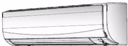
natural_image
Technical line drawing of a cylindrical object with horizontal grooves (no text or symbols)Operation manual
Daikin room air conditioner
Betriebsanleitung
2 About the system 2
2.1 Indoor unit 2
2.2 About the user interface 3
2.2.1 Components: User interface 3
2.2.2 Status: User interface LCD 3
2.2.3 To operate the user interface.... 4
3 Before operation 4
3.1 To mount the user interface holder .... 4
3.2 To insert the batteries.... 4
3.3 To turn on the power supply.... 4
4 Operation 4
4.1 Operation range 4
4.2 When to use which feature.... 4
4.3 Operation mode and temperature setpoint.... 5
4.3.1 To start/slop operation mode and to set the temperature....5
4.3.2 Airflow rate....5
4.3.3 Airflow direction....6
4.3.4 Comfort airflow operation....6
4.3.5 Powerful operation....6
4.3.6 Econo operation....7
4.3.7 OFF/ON timer operation 7
5 Energy saving and optimum operation 7
6 Maintenance and service 7
6.1 Overview: Maintenance and service 7
6.2 To clean the indoor unit and user interface 8
6.3 To clean the front panel.... 8
6.4 About the air filters 8
6.5 To clean the air filters 8
6.6 To take following items into account before a long idle period.. 9
7 Troubleshooting 9
7.1 Symptoms that are NOT system malfunctions 9
7.1.1 Symptom: A sound like water flowing is heard ..... 9
7.1.2 Symptom: A blowing sound is heard....9
7.1.3 Symptom: A ticking sound is heard....9
7.1.4 Symptom: A whistling sound is heard....9
7.1.5 Symptom: A clicking sound during operation or idle time is heard 9
7.1.6 Symptom: A clapping sound is heard 9
7.1.7 Symptom: The units can give off odours.... 10
7.1.8 Symptom: The outdoor fan rotates while the air conditioner is not in operation 10
7.2 Solving problems based on error codes.... 10
8 Disposal 10
1 About the documentation
1.1 About this document
Thank you for purchasing this product. Please:
- Keep the documentation for future reference.
Target audience
End users

INFORMATION
This appliance is intended to be used by expert or trained users in shops, in light industry, and on farms, or for commercial and household use by lay persons.
Documentation set
This document is part of a documentation set. The complete set consists of:
- General safety precautions:
- Safety instructions that you must read before operating your system
- Format: Paper (in the box of the indoor unit)
- Operation manual:
- Quick guide for basic usage
- Format: Paper (in the box of the indoor unit)
- User reference guide:
- Detailed step-by-step instructions and background information for basic and advanced usage
- Format: Digital files on http://www.daikineurope.com/support-and-manuals/product-information/
Latest revisions of the supplied documentation may be available on the regional Daikin website or via your installer.
The original documentation is written in English. All other languages are translations.
2 About the system

WARNING: FLAMMABLE MATERIAL
The refrigerant inside this unit is mildly flammable.

NOTICE
Do NOT use the system for other purposes. In order to avoid any quality deterioration, do NOT use the unit for cooling precision instruments, food, plants, animals, or works of art.
2.1 Indoor unit

CAUTION
Do NOT insert fingers, rods or other objects into the air inlet or outlet. When the fan is rotating at high speed, it will cause injury.

INFORMATION
The sound pressure level is less than 70 dBA.

WARNING
- Do NOT modify, disassemble, remove, reinstall or repair the unit yourself as incorrect dismantling or installation may cause an electrical shock or fire. Contact your dealer.
- In case of accidental refrigerant leaks, make sure there are no naked flames. The refrigerant itself is entirely safe, non-toxic and mildly flammable, but it will generate toxic gas when it accidentally leaks into a room where combustible air from fan heaters, gas cookers, etc. is present. Always have qualified service personnel confirm that the point of leakage has been repaired or corrected before resuming operation.

INFORMATION
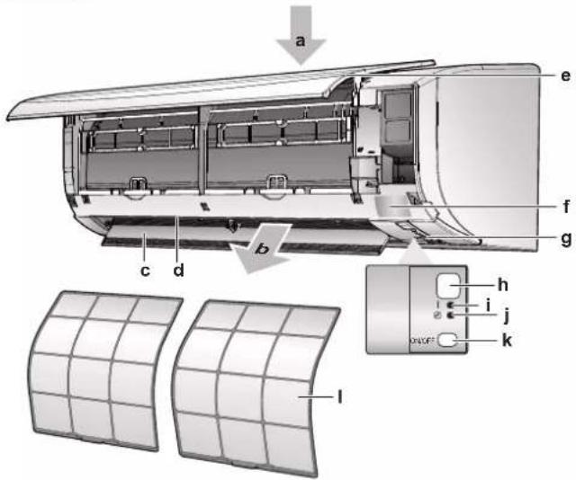
The following figures are just examples and may NOT completely match your system layout.
text_image
Technical diagram of an airship module with labeled components and internal grid structure, including a magnified view of the panel.a Air inlet
b Air outlet
c Flap (horizontal blade)
d Louvers (vertical blades)
e Front panel
f Model name plate
g Room temperature sensor
h Signal receiver
i Operation indicator (green)
j Timer lamp (orange)
k Indoor unit ON/OFF switch
I Air filter
ON/OFF button
If the user interface is missing, you can use the ON/OFF button on the indoor unit to start/stop operation. When operation is started using this button, the following settings are used:
- Operation mode = Automatic
- Temperature setting = 25°C
- Airflow rate = Automatic
2.2 About the user interface
- Direct sunlight. Do NOT expose the user interface to direct sunlight.
- Dust. Dust on the signal transmitter or receiver will reduce sensitivity. Wipe off dust with a soft cloth.
- Fluorescent lights. Signal communication might be disabled if fluorescent lamps are in the room. In that case, contact your installer.
- Other appliances. If the user interface signals operate other appliances, move the other appliances, or contact your installer.
- Curtains. Make sure that the signal between the unit and the user interface is NOT blocked by curtains or other objects.

NOTICE
- Do NOT drop the user interface.
- Do NOT let the user interface get wet.
2.2.1 Components: User interface
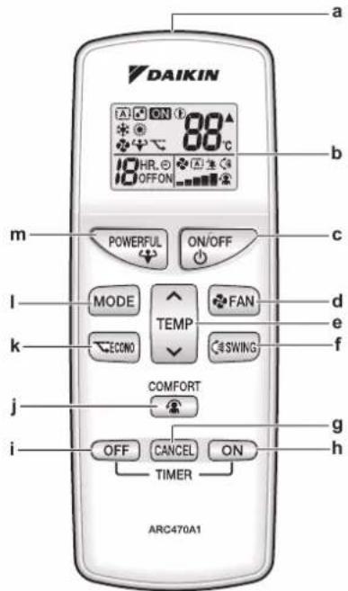
text_image
DAIKIN 88°C 10HR,0 OFFON POWERFUL ON/OFF MODE FAN ECONO SWING TEMP COMFORT OFF CANCEL ON TIMER ARC470A1 a b c d e f g h m l k j ia Signal transmitter
b LCD display
c ON/OFF button
d Fan setting button
e Temperature adjustment button
f Swing button
g Timer cancel button
h ON timer button
I OFF timer button
j Comfort airflow button
k Econo button
I Mode selector button
m Powerful button
2.2.2 Status: User interface LCD
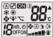
| Icon Description | |
| Operation mode = Automatic | |
| Operation mode = Drying | |
| Operation mode = Heating | |
| Operation mode = Cooling | |
| Operation mode = Fan only | |
| Powerful operation is active | |
| Econo operation is active | |
| ON | Operation is active |
| ▲ | The indoor unit receives a signal from the user interface |
| 88°C | Current temperature setting |
| Airflow rate = Automatic | |
| Airflow rate = Indoor unit quiet | |
3 Before operation
| Icon Description | ||
 | Airflow rate = High | |
 | Airflow rate = Medium high | |
| [XXY0] | Airflow rate = Medium | |
| [A2WG] | Airflow rate = Medium low | |
 | Airflow rate = Low | |
 | Comfort operation is active | |
| [KC2G] | Auto vertical swing is active | |
 | ON timer is active | |
 | OFF timer is active | |
2.2.3 To operate the user interface
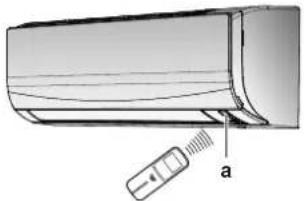
natural_image
Diagram of a car air conditioner unit with a sensor attached to the side panel (no text or symbols present)a Signal receiver
1 Aim the signal transmitter at the signal receiver on the indoor unit (maximum distance for communication is 7 m).
Result: When the indoor unit receives a signal from the user interface, you will hear a sound:
| Sound Description | |
| Beep-beep Operation starts. | |
| Beep Setting changes. | |
| Long beep Operation stops. |
3 Before operation
3.1 To mount the user interface holder
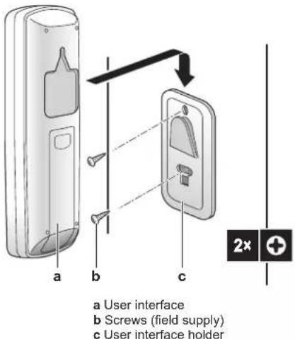
text_image
a User interface b Screws (field supply) c User interface holder1 Choose a place where the signals reach the unit.
2 Attach the holder with screws to the wall or a similar location.
3 Hang the user interface on the user interface holder.
3.2 To insert the batteries
The batteries will last for about 1 year.
1 Remove the back cover.
2 Insert both batteries at once.
3 Put the cover back.
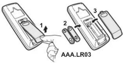
text_image
1 2 3 AAA.LR033.3 To turn on the power supply
1 Turn the circuit breaker on.
Result: The flap of the indoor unit will open and close to set the reference position.
4 Operation
4.1 Operation range
| Operation mode | Operation range |
| Cooling^(a)(b) | Outdoor temperature: -10~46°C DBIndoor temperature: 18~32°C DBIndoor humidity: ≤80% |
| Heating^(a) | Outdoor temperature: -15~24°C DBIndoor temperature: 10~30°C DB |
| Drying^(a) | Outdoor temperature: -10~46°C DBIndoor temperature: 18~32°C DBIndoor humidity: ≤80% |
(a) A safety device might stop the operation of the system if the unit runs outside its operation range.
(b) Condensation and water dripping might occur if the unit runs outside its operation range.
4.2 When to use which feature
You can use the following table to determine which features to use:
| Feature | Tasks | |
| Basic features | ||
| To start/stop the system and to set the temperature:Heat up or cool down a room.Blow air in a room without heating or cooling.Decrease the humidity in a room.In Automatic mode, automatically select an appropriate temperature and operation mode. | ||
| To adjust the airflow direction (swing or fixed position). | ||
| Feature Tasks | ||
| [H026] | Airflow rate | To adjust the amount of air blown into the room.To run more quietly. |
| Advanced features | ||
 | Econo | To use the system when you are also using other power-consuming appliances.To save energy. |
 | Comfort | To provide a comfortable airflow that does NOT come in direct contact with people. |
| Powerful | To cool down or heat up the room quickly. | |
 | ON timer + OFFtimer | To automatically turn ON or OFF the system. |
4.3 Operation mode and temperature setpoint
When. Adjust the system operation mode and set the temperature when you want to:
- Heat up or cool down a room
- Blow air in a room without heating or cooling
- Decrease the humidity in a room
What. The system operates differently, depending on the user selection.
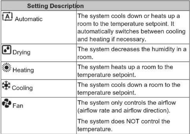 |
Additional info:
- Outside temperature. The system's cooling or heating effect decreases when the outside temperature is too high or too low.
- Defrost operation. During heating operation, frost might occur on the outdoor unit and decrease the heating capacity. In that case, the system automatically switches to defrosting operation to remove the frost. During defrosting operation, hot air is NOT blown from the indoor unit.
4.3.1 To start/stop operation mode and to set the temperature
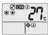
ON: Unit is operating.
(A): Operation mode = Automatic
: Operation mode = Drying
: Operation mode = Heating
: Operation mode = Cooling
: Operation mode = Fan only
88°C: Shows the set temperature.
1 Press MODE one or more times to select the operation mode.
Result: The mode will be set in the following sequence:

2 Press to start operation.
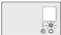
Result: QN displayed on the LCD.
Result: The operation lamp lights up.

3 Press √ or ∧ on the √ button one or more times to lower or raise the temperature.
Note: When using drying or fan only mode, you cannot adjust the temperature.
4 Press to stop operation.
Result: CN appears from the LCD.
Result: The operation lamp goes off.
4.3.2 Airflow rate
1 Press to choose:
| 5 airflow rate levels, from "o" | |
| Automatic airflow rate operation | |
| Indoor unit quiet operation. When the airflow rate is set to ", the noise from the unit will be reduced. |

INFORMATION
- If the unit reaches the temperature setpoint in cooling or heating mode, the fan will stop operating.
- When using drying operation mode, you CANNOT adjust the airflow rate setting.
To adjust the airflow rate
1 Press to change the airflow setting as follows:

4.3.3 Airflow direction
When. Adjust the airflow direction as desired.
What. The system directs the airflow differently, depending on the user selection (swinging or fixed position). It does so by moving the vertical blades.
| Setting Airflow direction | |
| Vertical auto swing | Moves up and down. |
| [—] Stays in a fixed position. | |

CAUTION
- ALWAYS use a user interface to adjust the angle of the flap. When the flap is swinging and you move it forcibly by hand, the mechanism will break.
- Be careful when adjusting the louvers. Inside the air outlet, a fan is rotating at high speed.
Note: The movable range of the flap varies according to the operation mode. The flap will stop at the upper position when the airflow rate is changed to low during the up and down swing setting.
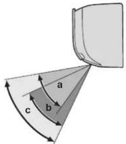
text_image
a b ca Flap range in cooling or drying operation
b Flap range in hating operation
c Flap range in fan only operation
To adjust the airflow direction
1 To use auto swing, press . SWING
Result: Will appear on the LCD.
Result: The flap (horizontal blade) will begin to swing.
2 To use fixed position, press when the flap reaches the desired position.
Result: disappears from the LCD.
To adjust the louvers (vertical blades)
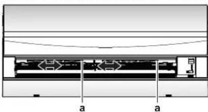
1 Hold 1 or both knobs and move the louvers.
text_image
a aa Knobs

INFORMATION
When the unit is installed in a corner of a room, the direction of the louvers should be facing away from the wall. Efficiency will drop if a wall blocks the air.
4.3.4 Comfort airflow operation
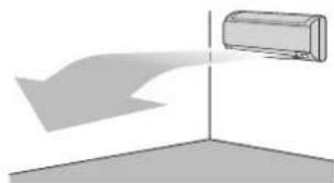
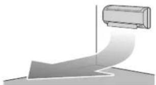
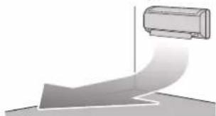
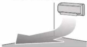
This operation can be used in heating or cooling operation mode. It will provide a comfortable wind that will NOT come in direct contact with people. The system automatically sets the fixed airflow position upward in Cooling and downward in Heating operation mode.
Cooling operation mode
natural_image
Simple 3D diagram showing a cylinder approaching a vertical axis, with no text or symbols present.Heating operation mode
natural_image
Diagram of a curved pipe or duct with a cylindrical object above it, no text or symbols present
INFORMATION
Powerful and Comfort airflow operation CANNOT be used at the same time. The last selected function takes priority. If the vertical automatic swing is selected, Comfort airflow operation will be cancelled.
To start/stop Comfort airflow operation
COMFORT
1 Press to start.
Result: The flap position will change, 📁 is displayed on the LCD, and the airflow rate is set to automatic.
| Mode | Position of flap... |
| Cooling/Drying | Up |
| Heating | Down |
COMFORT

Result: The flap will return to the position from before the Comfort airflow mode; 🙏 disappears from the LCD.
4.3.5 Powerful operation
This operation quickly maximizes the cooling/heating effect in any operation mode. You can get the maximum capacity.

INFORMATION
Powerful operation CANNOT be used together with Econo and Comfort airflow operation. The last selected function takes priority.
Powerful operation will NOT increase the capacity of the unit if it already operates at maximum capacity.
To start/stop Powerful operation
1 Press

Result: is displayed on the LCD. Powerful operation runs for 20 minutes; after that, operation returns to the previously set mode.
2 Press

Result: disappears from the LCD.
Note: Powerful operation can be set only when the unit is running. If you press ON/OFF or if you change operation mode, operation will be cancelled; disappears from the LCD.
4.3.6 Econo operation
This is a function which enables efficient operation by limiting the maximum power consumption value. This function is useful for cases in which attention should be paid to ensure a circuit breaker will not trip when the product runs alongside other appliances.

INFORMATION
- Powerful and Econo operation CANNOT be used at the same time. The last selected function takes priority.
- Econo operation reduces power consumption of the outdoor unit by limiting the rotation speed of the compressor. If power consumption is already low, Econo operation will NOT further reduce power consumption.
To start/stop Econo operation
1 Press

Result: is displayed on the LCD.
2 Press

Result: disappears from the LCD.
4.3.7 OFF/ON timer operation
Timer functions are useful for automatically switching the air conditioner off/on at night or in the morning. You can also use OFF timer and ON timer in combination.

INFORMATION
Program the timer again in case of:
- A breaker has turned the unit off.
- A power failure.
- After replacing batteries in the user interface.
To start/stop ON timer operation
1 Press

Result: is displayed on the LCD and the timer lamp lights up.

INFORMATION
Each time is pressed, the time setting advances by 1 hour. The timer can be set between 1 to 12 hours.
2 Press

Result: ON disappears from the LCD and the timer lamp goes off.
To start/stop OFF timer operation
1 Press

Result: .OFF is displayed on the LCD and the timer lamp lights up.

INFORMATION
Each time is pressed, the time setting advances by 1 hour. The timer can be set between 1 to 9 hours.
2 Press

Result: .OFF disappears from the LCD and the timer lamp goes off.

INFORMATION
When you set the ON/OFF timer, the time setting is stored in the memory. The memory will be reset when the user interface batteries are replaced.
Use of night set mode in combination with OFF timer
The air conditioner automatically adjusts the temperature setting (0.5°C up in cooling, 2.0°C down in heating) to prevent excessive cooling/heating and ensure a comfortable sleeping temperature.
To combine OFF timer and ON timer
1 To set the timers, refer to "To start/stop OFF timer operation" [▶7] and "To start/stop ON timer operation" [▶7].
Result: OFF and ON are displayed on the LCD.
2 Example of what is displayed on the LCD if you combine the 2

5 Energy saving and optimum operation

INFORMATION
- Even if the unit is turned OFF, it consumes electricity.
- When the power turns back on after a power break, the previously selected mode will be resumed.

CAUTION
NEVER expose little children, plants or animals directly to the airflow.

NOTICE
Do NOT place objects below the indoor and/or outdoor unit that may get wet. Otherwise condensation on the unit or refrigerant pipes, air filter dirt or drain blockage may cause dripping, and objects under the unit may get dirty or damaged.

WARNING
Do NOT place a flammable spray bottle near the air conditioner and do NOT use sprays near the unit. Doing so may result in a fire.

CAUTION
Do NOT operate the system when using a room fumigation-type insecticide. Chemicals could collect in the unit, and endanger the health of people who are hypersensitive to chemicals.
6 Maintenance and service
6.1 Overview: Maintenance and service
The installer has to perform a yearly maintenance.
About the refrigerant
This product contains fluorinated greenhouse gases. Do NOT vent gases into the atmosphere.
Refrigerant type: R32
Global warming potential (GWP) value: 675

NOTICE
Applicable legislation on fluorinated greenhouse gases requires that the refrigerant charge of the unit is indicated both in weight and CO_2 equivalent.
Formula to calculate the quantity in CO_2 equivalent tonnes: GWP value of the refrigerant × total refrigerant charge [in kg] / 1000
Please contact your installer for more information.

WARNING
The refrigerant inside the unit is mildly flammable, but normally does NOT leak. If the refrigerant leaks in the room and comes in contact with fire from a burner, a heater, or a cooker, this may result in fire, or the formation of a harmful gas.
Turn off any combustible heating devices, ventilate the room, and contact the dealer where you purchased the unit.
Do NOT use the unit until a service person confirms that the part from which the refrigerant leaked has been repaired.

WARNING
- Do NOT pierce or burn refrigerant cycle parts.
- Do NOT use cleaning materials or means to accelerate the defrosting process other than those recommended by the manufacturer.
- Be aware that the refrigerant inside the system is odourless.

WARNING
The appliance shall be stored in a room without continuously operating ignition sources (example: open flames, an operating gas appliance or an operating electric heater).

NOTICE
Maintenance MUST be done by an authorised installer or service agent.
We recommend performing maintenance at least once a year. However, applicable legislation might require shorter maintenance intervals.

DANGER: RISK OF ELECTROCUTION
To clean the air conditioner or air filter, be sure to stop operation and turn all power supplies OFF. Otherwise, an electrical shock and injury may result.

WARNING
To prevent electrical shocks or fire:
- Do NOT rinse the unit.
- Do NOT operate the unit with wet hands.
- Do NOT place any objects containing water on the unit.

CAUTION
After a long use, check the unit stand and fitting for damage. If damaged, the unit may fall and result in injury.

CAUTION
Do NOT touch the heat exchanger fins. These fins are sharp and could result in cutting injuries.

WARNING
Be careful with ladders when working in high places.
6.2 To clean the indoor unit and user interface

NOTICE
- Do NOT use gasoline, benzene, thinner, polishing powder or liquid insecticide. Possible consequence: Discoloration and deformation.
- Do NOT use water or air of 40°C or higher. Possible consequence: Discoloration and deformation.
- Do NOT use polishing compounds.
- Do NOT use a scrubbing brush. Possible consequence: The surface finishing peels off.
- As an end user, you may NEVER clean inside parts of the unit by yourself; this work must be performed by a qualified service person. Contact your dealer.

DANGER: RISK OF ELECTROCUTION
Before cleaning, be sure to stop the operation, turn the breaker OFF or pull out the supply cord. Otherwise, an electrical shock and injury may result.
1 Clean with a soft cloth. If it is difficult to remove stains, use water or a neutral detergent.
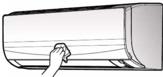
6.3 To clean the front panel
natural_image
Line drawing of a hand cleaning a large air conditioner cover (no text or symbols)1 Clean the front panel with a soft cloth. If it is difficult to remove stains, use water or a neutral detergent.
6.4 About the air filters
Operating the unit with dirty filters means that the filter:
- CANNOT deodorise the air,
- CANNOT clean the air,
- poor heating/cooling,
- causes odour.
6.5 To clean the air filters
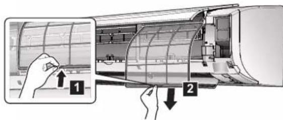
1 Push the tab at the centre of each air filter, then pull it down.
2 Pull out the air filters.
text_image
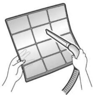
Diagram showing air conditioner installation steps with labeled components and directional arrows3 Wash the air filters with water or clean them with a vacuum cleaner.
natural_image
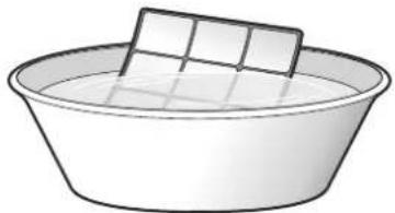
Illustration of hands holding a grid-based tablet with a pen, no text or symbols present4 Soak in lukewarm water for about 10 to 15 minutes.
natural_image
Simple line drawing of a basin with a rectangular object on top (no text or symbols)5 Install all filters back in their original positions.

INFORMATION
- If the dust does NOT come off easily, wash them with a neutral detergent diluted in lukewarm water. Dry the air filters in the shade.
- It is recommended to clean the air filters every 2 weeks.
6.6 To take following items into account before a long idle period
Operate the unit in fan only mode for several hours to dry the inside of the unit.
1 Press and select fan only operation.
2 Press to start operation.
3 After operation stops, turn the breaker off.
4 Clean the air filters and replace them in their original position.
5 Remove the batteries from the user interface.

INFORMATION
It is recommended to have periodical maintenance performed by a specialist. For specialist maintenance, contact your dealer. Maintenance costs shall be borne by the customer.
In certain operating conditions the inside of the unit may get dirty after several seasons of use. This results in poor performance.
7 Troubleshooting
If one of the following malfunctions occur, take the measures shown below and contact your dealer.

WARNING
Stop operation and shut OFF the power if anything unusual occurs (burning smells etc.).
Leaving the unit running under such circumstances may cause breakage, electrical shock or fire. Contact your dealer.
The system MUST be repaired by a qualified service person.
| Malfunction Measure | |
| If a safety device such as a fuse, a breaker or an earth leakage breaker frequently actuates or the ON/OFF switch does NOT properly work. | Turn OFF the main power switch. |
| If water leaks from the unit. Stop the operation. | |
| The operation switch does NOT work well. | Turn OFF the power supply. |
| If the user interface display indicates the unit number, the operation lamp flashes and the malfunction code appears. | Notify your installer and report the malfunction code. |
If the system does NOT operate properly except for the above mentioned cases and none of the above mentioned malfunctions is evident, investigate the system in accordance with the following procedures.

INFORMATION
Refer to the reference guide located on http://www.daikineurope.com/support-and-manuals/product-information/ for more troubleshooting tips.
If after checking all above items, it is impossible to fix the problem yourself, contact your installer and state the symptoms, the complete model name of the unit (with manufacturing number if possible) and the installation date (possibly listed on the warranty card).
7.1 Symptoms that are NOT system malfunctions
The following symptoms are NOT system malfunctions:
7.1.1 Symptom: A sound like water flowing is heard
- This sound is caused by the refrigerant flowing in the unit.
- This sound may be generated when water is flowing away from the unit during cooling or drying operation.
7.1.2 Symptom: A blowing sound is heard
This sound is generated when the direction of the refrigerant flow is changed (e.g. when switching from cooling to heating).
7.1.3 Symptom: A ticking sound is heard
This sound is generated when the unit slightly expands or contracts with changes in temperature.
7.1.4 Symptom: A whistling sound is heard
This sound is generated by the refrigerant flowing during defrost operation.
7.1.5 Symptom: A clicking sound during operation or idle time is heard
This sound is generated when the refrigerant control valves or electrical parts operate.
7.1.6 Symptom: A clapping sound is heard
This sound is generated when an external device sucks air out of the room (e.g. exhaust fan, extractor hood) while the doors and windows in the room are closed. Open the doors or windows, or turn off the device.
7.1.7 Symptom: The units can give off odours
The unit can absorb the smell of rooms, furniture, cigarettes, etc., and then emit it again.
7.1.8 Symptom: The outdoor fan rotates while the air conditioner is not in operation
- After operation has stopped. The outdoor fan continues to rotate for another 30 seconds for system protection.
- While the air conditioner is not in operation. When the outdoor temperature is very high, the outdoor fan starts to rotate for system protection.
7.2 Solving problems based on error codes
Fault diagnosis by user interface
If the unit runs into a problem, you can identify the fault by checking the error code by the user interface. It is important to understand the problem and take measures before resetting the error code. This should be done by a licensed installer or your local dealer.

INFORMATION
See the service manual for:
- The complete list of error codes
- A more detailed troubleshooting guideline for each error
To check the error code by the user interface
1 Aim the user interface at the unit and press for about 5 seconds.
Result: 00 links in the temperature setting display section.
2 Aim the user interface at the unit and press repeatedly until a continuous beep is heard.
Result: The code is now displayed on the display.

INFORMATION
- A short beep and 2 consecutive beeps indicate non-corresponding codes.
- To cancel the code display, hold for 5 seconds. The code will also disappear from the display if the button is NOT pressed within 1 minute.
System
| Error code | Description |
| 00 | Normal |
| U0 | Refrigerant shortage |
| U2 | Overvoltage detection |
| U4 | Signal transmission error (between indoor and outdoor unit) |
| UR | Indoor/outdoor unit combination fault |
Indoor unit
| Error code | Description |
| R1 | Indoor unit PCB abnormality |
| R5 | Freeze-up protection or high-pressure control |
| R6 | Fan motor (DC motor) abnormality |
| C9 | Room temperature thermistor abnormality |
Outdoor unit
| Error code | Description |
| ER | 4-way valve abnormality |
| Error code | Description |
| E1 | Outdoor unit PCB abnormality |
| E5 | Overload activation (compressor overload) |
| E6 | Compressor lock |
| E7 | DC fan lock |
| E8 | Input power overcurrent |
| F3 | Discharge pipe temperature control |
| F6 | High-pressure control (in cooling mode) |
| H0 | Compressor system sensor abnormality |
| H6 | Position sensor abnormality |
| H8 | DC voltage / current sensor abnormality |
| H9 | Outdoor temperature thermistor abnormality |
| J3 | Discharge pipe thermistor abnormality |
| J6 | Outdoor heat exchanger thermistor abnormality |
| L3 | Electrical parts heat error |
| L4 | Radiation fin temperature rise |
| L5 | Inverter instantaneous overcurrent (DC) |
| P4 | Radiation fin thermistor abnormality |
| F8 | Compressor internal temperature error |
8 Disposal

NOTICE
Do NOT try to dismantle the system yourself: dismantling of the system, treatment of the refrigerant, oil and other parts MUST comply with applicable legislation. Units MUST be treated at a specialised treatment facility for reuse, recycling and recovery.
Inhaltsverzeichnis
natural_image
Diagram of a car air conditioner unit with a sensor attached to the side panel (no text or symbols present)a Signalempfänger
GEFAHR: STROMSCHLAGGEFAHR
GEFAHR: STROMSCHLAGGEFAHR
natural_image
Line drawing of a hand cleaning a large cylindrical object (no text or symbols)text_image
Diagram showing airflow or ventilation system with labeled components and directional arrows indicating movementnatural_image
Illustration of hands holding a grid-based object with a tool, no text or symbols presentnatural_image
Simple line drawing of a bowl with a square object on top (no text or symbols)natural_image
Diagram of a car air conditioner unit with a sensor attached, showing internal components and label 'a' (no text or symbols beyond label)natural_image
Diagram showing airflow or spray from a rectangular container onto a vertical axis, with no text or symbols present.Mode chauffage
natural_image
Diagram of a curved pipe or duct with a cylindrical component above it, no text or symbols present
INFORMATION
natural_image
Line drawing of a hand cleaning a large air conditioner cover (no text or symbols)text_image
Diagram showing air conditioner installation steps with labeled components and directional arrowsnatural_image
Illustration of hands holding a grid-based object with a tool, no text or symbols presentnatural_image
Simple line drawing of a basin with a rectangular object on top (no text or symbols)WAARSCHUWING: ONTVLAMBAAR MATERIAAL
natural_image
Diagram of a car air conditioner unit with a sensor attached, labeled 'a' (no text or symbols on the diagram itself)a Signaalontvanger
natural_image
Line drawing of a hand cleaning a large air conditioner cover (no text or symbols)text_image
Diagram showing airflow or ventilation process with labeled components and directional arrowsnatural_image
Illustration of hands holding a grid-based object with a tool, no text or symbols presentnatural_image
Simple line drawing of a basin with a rectangular object on top (no text or symbols)natural_image
Diagram of a car air conditioner unit with a sensor attached to the side panel (no text or symbols present)a Receptor de señal
natural_image
Line drawing of a hand cleaning a large air conditioner cover (no text or symbols)text_image
Diagram showing airflow or ventilation process with labeled components and directional arrowsnatural_image
Illustration of hands holding a grid-based object with a tool, no text or symbols presentnatural_image
Simple line drawing of a basin with a rectangular object on top (no text or symbols)natural_image
Diagram of a car air conditioner unit with a sensor attached to the side panel (no text or symbols present)natural_image
Simple 3D diagram showing a cylinder approaching a vertical axis with a shaded triangular plane (no text or symbols)natural_image
Diagram of a curved pipe or duct with a rectangular object above it, no text or symbols present.4 Funzionamento

INFORMAZIONE
natural_image
Line drawing of a hand cleaning a large air conditioner cover (no text or symbols)text_image
Diagram showing airflow or ventilation system with labeled components and directional arrows indicating movementnatural_image
Illustration of hands holding a grid-based object with a tool, no text or symbols presentnatural_image
Simple line drawing of a bowl with a square dish on top (no text or symbols)natural_image
Diagram of a car air conditioner unit with a sensor attached to the side panel (no text or symbols present)α Δέκτης σήματος
natural_image
Two identical diagrams showing airflow or fluid flow between a rectangular object, with no text, numbers, or symbols present.
ΠΛΗΡΟΦΟΡΙΕΣ
natural_image
Line drawing of a hand cleaning a large air conditioner cover (no text or symbols)text_image
Diagram showing airflow or ventilation process with labeled components and directional arrowsnatural_image
Illustration of hands holding a grid-based object with scissors, no text or symbols presentnatural_image
Simple line drawing of a basin with a rectangular object on top (no text or symbols)natural_image
Diagram of a car air conditioner unit with a sensor attached to the side panel (no text or symbols present)a Recetor de sinal
natural_image
Simple 3D diagram showing a cylinder above a vertical axis with a shaded arrow, no text or symbols present.Modo de aquecimento
natural_image
Pure diagram of a curved pipe or duct with a rectangular component above it, no text or symbols present.
INFORMAÇÕES
natural_image
Line drawing of a hand cleaning a large air conditioner cover (no text or symbols)text_image
Diagram showing air conditioner unit with labeled parts and directional arrows indicating process stepsnatural_image
Illustration of hands using scissors to cut a grid on a surface (no text or symbols)natural_image
Simple line drawing of a basin with a rectangular object on top (no text or symbols)text_image
Technical diagram of an air conditioner unit with labeled components and internal structure, including a close-up of two solar panels and a component panel.natural_image
Diagram of a car air conditioner unit with a sensor attached to the side panel (no text or symbols present)а Приемник сигнала
natural_image
Simple 3D diagram showing a curved surface and a rectangular object with a vertical line, no text or symbols present.natural_image
Diagram of a curved pipe or duct with a cylindrical component above it, no text or symbols present.
ИНФОРМАЦИЯ
natural_image
Line drawing of a hand cleaning a large cylindrical object (no text or symbols)text_image
Diagram showing airflow or ventilation process with labeled components and directional arrowsnatural_image
Illustration of hands using a power tool to spread a grid on a surface (no text or symbols visible)natural_image
Simple line drawing of a basin with a rectangular object on top (no text or symbols)natural_image
Diagram of a car air conditioner unit with a sensor attached to the side panel (no text or symbols present)a Sinyal alici
natural_image
Line drawing of a hand cleaning a large air conditioner cover (no text or symbols)7 Sorun giderme
text_image
Diagram showing airflow or ventilation process with labeled components and directional arrowsnatural_image
Illustration of hands holding a grid-based object with a tool, no text or symbols presentnatural_image
Simple line drawing of a bowl with a square dish on top (no text or symbols)natural_image
Blank grid paper with no text, numbers, or symbols

natural_image
Blank grid paper with no text, numbers, or symbolsDAIKIN ISITMA VE SOĞUTMA SİSTEMLERİ SAN.TİC. A.Ş.
Gülsuyu Mahallesi, Fevzi Çakmak Caddesi, Burçak Sokak, No:20, 34848 Maltepe
İSTANBUL / TÜRKİYE
Tel: 0216 453 27 00