W10915235 - Cooker KITCHENAID - Free user manual and instructions
Find the device manual for free W10915235 KITCHENAID in PDF.

User questions about W10915235 KITCHENAID
0 question about this device. Answer the ones you know or ask your own.
Ask a new question about this device
Download the instructions for your Cooker in PDF format for free! Find your manual W10915235 - KITCHENAID and take your electronic device back in hand. On this page are published all the documents necessary for the use of your device. W10915235 by KITCHENAID.
USER MANUAL W10915235 KITCHENAID
HIGH ALTITUDE KIT INSTALLATION INSTRUCTIONS
To convert range for elevations above 6,560 ft (1999.5 m)
INSTRUCTIONS D'INSTALLATION POUR TROUSSE D'UTILISATION EN HAUTE ALTITUDE
Natural Gas (NG) High Altitude Kit Contains:
1 - Orifice spud, oven bake
1 - Instruction sheet
Propane Gas (LP) High Altitude Kit Contains:
1 - Orifice spud, oven bake
1 - Instruction sheet
Your safety and the safety of others are very important.
We have provided many important safety messages in this manual and on your appliance. Always read and obey all safety messages.

This is the safety alert symbol.
This symbol alerts you to potential hazards that can kill or hurt you and others.
All safety messages will follow the safety alert symbol and either the word "DANGER" or "WARNING."
These words mean:

You can be killed or seriously injured if you don't immediately follow instructions.

You can be killed or seriously injured if you don't follow instructions.
All safety messages will tell you what the potential hazard is, tell you how to reduce the chance of injury, and tell you what can happen if the instructions are not followed.
WARNING: If the information in these instructions is not followed exactly, a fire or explosion may result causing property damage, personal injury or death.
- Do not store or use gasoline or other flammable vapors and liquids in the vicinity of this or any other appliance.
-
WHAT TO DO IF YOU SMELL GAS:
-
Do not try to light any appliance.
- Do not touch any electrical switch.
- Do not use any phone in your building.
- Immediately call your gas supplier from a neighbor's phone. Follow the gas supplier's instructions.
- If you cannot reach your gas supplier, call the fire department.
- Installation and service must be performed by a qualified installer, service agency or the gas supplier.
WARNING: Gas leaks cannot always be detected by smell.
Gas suppliers recommend that you use a gas detector approved by UL or CSA.
For more information, contact your gas supplier.
If a gas leak is detected, follow the "What to do if you smell gas" instructions.
IMPORTANT: Do not install a ventilation system that blows air downward toward this gas cooking appliance. This type of ventilation system may cause ignition and combustion problems with this gas cooking appliance resulting in personal injury or unintended operation.
In the State of Massachusetts, the following installation instructions apply:
■ Installations and repairs must be performed by a qualified or licensed contractor, plumber, or gasfitter qualified or licensed by the State of Massachusetts.
■ If using a ball valve, it shall be a T-handle type.
■ A flexible gas connector, when used, must not exceed 3 feet.
GAS CONVERSIONS
IMPORTANT: Gas conversions must be done by a qualified installer. Before proceeding with the conversion, shut off the gas supply to the range prior to disconnecting the electrical power.
WARNING
This conversion kit shall be installed by a qualified service agency in accordance with the manufacturer's instructions and all applicable codes and requirements of the authority having jurisdiction. If the information in these instructions is not followed exactly, a fire, explosion or production of carbon monoxide may result causing property damage, personal injury or loss of life. The qualified service agency is responsible for the proper installation of this kit. The installation is not proper and complete until the operation of the converted appliance is checked as specified in the manufacturer's instructions supplied with this kit.
WARNING
Explosion Hazard
Use a new CSA International approved gas supply line. Install a shut-off valve.
Securely tighten all gas connections.
If connected to LP, have a qualified person make sure gas pressure does not exceed 14" (36 cm) water column.
Examples of a qualified person include:
licensed heating personnel, authorized gas company personnel, and authorized service personnel.
Failure to do so can result in death, explosion, or fire.
LP Gas Conversion
WARNING
natural_image
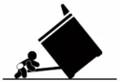
Silhouette of a person pushing a large block on a flat surface (no text or symbols)Tip Over Hazard
A child or adult can tip the range and be killed.
Install anti-tip bracket to floor or wall per installation instructions.
Slide range back so rear range foot is engaged in the slot of the anti-tip bracket.
Re-engage anti-tip bracket if range is moved.
Do not operate range without anti-tip bracket installed and engaged.
Failure to follow these instructions can result in death or serious burns to children and adults.
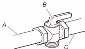
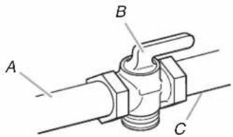
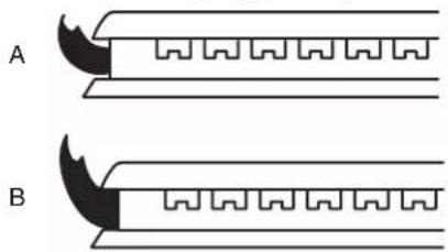
- Turn the manual shut-off valve to the closed position.
text_image
A B CA. Gas supply line
B. Manual shut-off valve closed position
C. To range
- Unplug range or disconnect power.
To Convert Gas Pressure Regulator (LP Gas)
See the "Gas Conversion Instructions" section in the Installation Instructions provided with the range for proper regulator conversion.
To Convert Surface Burners (LP Gas)
Surface burners do not need conversion for high altitude. Only adjust surface burner valve. See the "Adjust Flame Height" section.
To Convert Oven Bake Burner (LP Gas)
Only the bake orifice needs to be converted for high altitude.
- Remove the oven racks and the oven door. See the "Oven Door" section in the Installation Instructions.
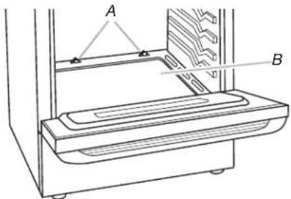
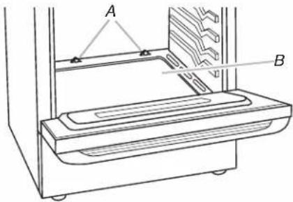
- Remove 2 screws and washers at the rear of the oven bottom.
- Lift the rear of the oven bottom up and back until the front of the panel is away from the front frame. Remove from oven and set it aside on a covered surface.
text_image
Technical diagram of a device with labeled components A and B, showing internal structure and mounting points.A. Screws
B. Oven bottom
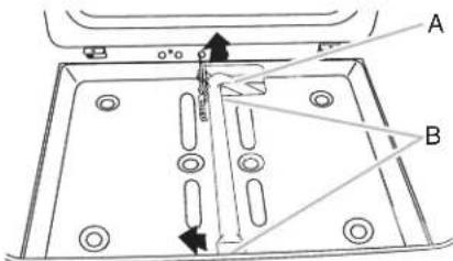
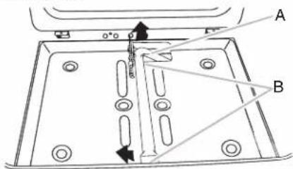
- Remove 2 screws from the bake burner.
- Slide the front of the bake burner to the side to remove tab from front of oven. Lift the back of the bake burner off the oven orifice, and set the bake burner aside. Do not disconnect the wire.
text_image
A B 0°0A. Bake burner
B. Screws

text_image
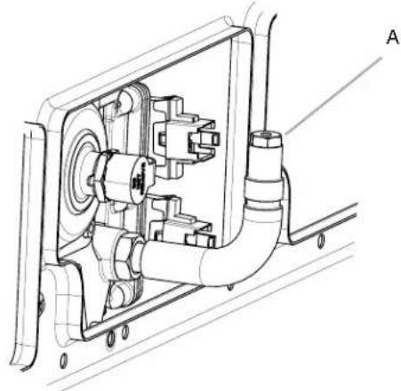
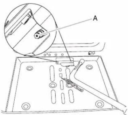
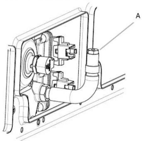
Technical diagram showing a mechanical assembly with labeled component 'A' and an inset detail view of a component being inserted.A. Oven orifice
- Apply masking tape to the end of a 38 " (1 cm) nut driver to help hold the gas orifice spud in the nut driver while changing it. Press nut driver down onto the gas orifice spud and remove by turning the Natural gas bake burner orifice spud counterclockwise to remove.
- Replace the current spud with a "107" spud. Install the LP gas bake burner orifice spud, turning it clockwise until snug. IMPORTANT: Do not overtighten.
natural_image
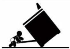
Technical line drawing of a mechanical assembly with no visible text or symbolsA. Orifice spud
- Position the back of the bake burner over the oven orifice, and then align the holes for the screws.
- Reattach the bake burner with 2 screws.
- Position the front of the oven bottom panel toward the front frame, and then lower the rear of the oven bottom panel into the oven.
- Reattach the oven bottom panel with 2 screws and 2 washers.
WARNING
natural_image
Silhouette of a person pushing a large block on a horizontal line (no text or symbols)Tip Over Hazard
A child or adult can tip the range and be killed.
Install anti-tip bracket to floor or wall per installation instructions.
Slide range back so rear range foot is engaged in the slot of the anti-tip bracket.
Re-engage anti-tip bracket if range is moved.
Do not operate range without anti-tip bracket installed and engaged.
Failure to follow these instructions can result in death or serious burns to children and adults.
- Turn the manual shut-off valve to the closed position.
text_image
A B CA. Gas supply line
B. Manual shut-off valve closed position
C. To range
- Unplug range or disconnect power.
To Convert Gas Pressure Regulator (Natural Gas)
See the "Gas Conversion Instructions" section in the Installation Instructions provided with the range for proper regulator conversion.
To Convert Surface Burners (Natural Gas)
Surface burners do not need conversion for high altitude. Only adjust surface burner valve. See the "Adjust Flame Height" section.
To Convert Oven Bake Burner (Natural Gas)
Only the bake orifice needs to be converted for high altitude.
- Remove the oven racks and the oven door. See the "Oven Door" section in the Installation Instructions.
- Remove 2 screws and washers at the rear of the oven bottom.
- Lift the rear of the oven bottom up and back until the front of the panel is away from the front frame. Remove from oven and set it aside on a covered surface.
text_image
A BA. Screws
B. Oven bottom
- Remove 2 screws from the bake burner.
- Slide the front of the bake burner to the side to remove tab from front of oven. Lift the back of the bake burner off the oven orifice, and set the bake burner aside. Do not disconnect the wire.
text_image
Technical diagram showing a mechanical component with labeled parts A and B, including angular annotations and directional arrows.A. Bake burner
B. Screws
text_image
Technical diagram showing a mechanical assembly with labeled component 'A' and magnified detail viewA. Oven orifice
-
Apply masking tape to the end of a 3/8'' (1 cm) nut driver to help hold the gas orifice spud in the nut driver while changing it. Press nut driver down onto the gas orifice spud and remove by turning the LP gas bake burner orifice spud counterclockwise to remove.
-
Replace the current spud with a "170" spud. Install the Natural gas bake burner orifice spud, turning it clockwise until snug.
IMPORTANT: Do not overtighten.
natural_image
Technical line drawing of a mechanical assembly with pipes and components (no text or symbols)A. Orifice spud
- Position the back of the bake burner over the oven orifice, and then align the holes for the screws.
- Reattach the bake burner with 2 screws.
- Position the front of the oven bottom panel toward the front frame, and then lower the rear of the oven bottom panel into the oven.
- Reattach the oven bottom panel with 2 screws and 2 washers.
Adjust Flame Height
Adjust Surface Burner Flame
Adjust the height of top burner flames. The cooktop "low" burner flame should be a steady blue flame approximately 1/4 (0.64 cm) high. LP gas flames have a slightly yellow tip.
natural_image
Diagram showing two types of mechanical or electrical components labeled A and B, with no visible text or symbols.A. Low flame
B. High flame
To Adjust Surface Burner:
The flame can be adjusted using the adjustment screw in the center of the valve stem. The valve stem is located directly underneath the control knob.
If the "Low" Flame Needs to Be Adjusted:
- Light 1 burner and turn to lowest setting.
- Remove the control knob.
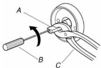
Hold the knob stem with a pair of pliers. Use a small flat-blade screwdriver to turn the screw located in the center of the control knob stem until the flame is the proper size. Turning the screw clockwise will increase the flame size, and turning the screw counterclockwise will decrease the flame size.
text_image
A B CA. Control knob stem
B. Screwdriver
C. Pliers
- Replace the control knob.
- Test the flame by turning the control from the low position to the high position, checking the flame at each setting.
- Repeat the previous steps for each burner.
SÉCURITÉ DE LA CONVERSION POUR ALIMENTATION
natural_image
Silhouette of a person pushing a large block on a horizontal line (no text or symbols)text_image
Technical diagram of a device with labeled components A and B, showing internal structure and mounting points.A. Vis
B. Fond du four
text_image
Technical diagram showing a mechanical component with labeled parts A and B, including directional arrows and dimension lines.text_image
Technical diagram showing a mechanical assembly with labeled component A and an inset view of a component being inserted.A. Orifice du four
natural_image
Technical line drawing of a mechanical assembly with pipes and components (no text or symbols)A. Gicleur
natural_image
Silhouette of a person pushing a large block on a horizontal line (no text or symbols)text_image
Technical diagram of a mechanical component with labeled parts A and B, showing internal features and directional arrows.text_image
Technical diagram showing a mechanical assembly with labeled component 'A' and an inset magnified view of a component.A. Orifice du four
natural_image
Technical line drawing of a mechanical assembly with pipes and components (no text or symbols)A. Gicleur