
KCID936SBL - Cooker KITCHENAID - Free user manual and instructions
Find the device manual for free KCID936SBL KITCHENAID in PDF.

| Product Type | Induction cooktop with integrated vent (36") |
| Brand | KitchenAid |
| Model | KCID936SBL |
| Dimensions (W x D x H) | 92.3 x 56.0 x 19.9 cm |
| Weight | 20.9 kg |
| Electrical Supply | 240 V (208 V), 60 Hz, 40 A, max power 8.0 kW (6.9 kW) |
| Surface Material | Ceramic glass |
| Number of Cooking Zones | 4 (induction) |
| Left front / left rear zones | 21 cm Ø (2300 W, Power 3000 W) / 17.5 cm Ø (1400 W, Power 2100 W) |
| Right front / right rear zones | 23 x 23 cm (2100 W, Power 3000 W) / 23 x 23 cm (2100 W, Power 3000 W) |
| Integrated hood | Ventilation device, levels 1-9 and Power, flow rate 332 cfm |
| Main functions | Timer, pause, keep warm (3 levels), automatic bridge, extra-large continuous zone system, control lock, cleaning lock, automatic ventilation system |
| Cleaning and maintenance | Ceramic glass top: scraper and special product; stainless steel grease filter washable (hand or dishwasher); suction nozzle; cleanable air circulation housing |
| Safety | Pan detection, automatic zone shut-off, overheat protection, child lock, hot surface indicator |
| Spare parts and repairability | Suction nozzle (W11751831), grease filter (W11751832), activated charcoal filter (W11751834), recycling kit (W11751835), frames, ceramic glass, touch control, fan, induction modules, etc. |
| General information | Energy Star certified, compliant with FCC/ICES-001, 128-page manual, professional installation recommended |
Frequently Asked Questions - KCID936SBL KITCHENAID
User questions about KCID936SBL KITCHENAID
0 question about this device. Answer the ones you know or ask your own.
Ask a new question about this device
Download the instructions for your Cooker in PDF format for free! Find your manual KCID936SBL - KITCHENAID and take your electronic device back in hand. On this page are published all the documents necessary for the use of your device. KCID936SBL by KITCHENAID.
USER MANUAL KCID936SBL KITCHENAID
Operating and installation instructions KCID930SBL, KCID936SBL
FR
Operating and installation instructions KCID930SBL, KCID936SBL
IMPORTANT: Save for the local electrical inspector's use.
IMPORTANT: An undercounter built-in oven cannot be installed under this product.
IMPORTANT: If installing a range hood or microwave hood combination above the range, follow the range hood or microwave hood combination installation instructions for dimensional clearances above the cooktop surface.
REMEMBER: When cooktop is in use, the entire cooktop area may become hot.

1 New Model / Old Model
| New Model Old Model | |
| KCID930SBL | JED3430GB |
| JIDT730SBL | JED3430GS |
| KCED600GBL | |
| KCED600GSS | |
| KCID936SBL | JED3536GB |
| JIDT836SBL | JED3536GS |
| KCED606GSS | |
| KCED606GBL | |
Tab. 1.1 New Model / Old Model
- These models showcase a direct replacement due to cut out sizes of products.
● HVAC professionals are still required for installation. - Ductwork changes might be required to fit adapter sizes on the new products.
Contents
1 New Model / Old Model 6
2 Cooktop Safety 9
3 Important safety instructions 10
4 General information 12
4.1 Validity of the operating and installation instructions ....12
4.2 Presentation of information......12
5 Technical data 13
5.1 KCID930SBL 13
5.2 Appliance dimensions KCID930SBL..13
5.3 KCID936SBL 14
5.4 Appliance dimensions KCID936SBL..14
6 Appliance description 15
6.1 Model description.... 15
6.2 System description ..... 15
6.2.1 Structure.... 15
6.2.2 Operating panel.... 15
6.2.3 7-segment display.... 16
6.2.4 Lighting 16
6.3 How the cooktop extractor works.....16
6.4 How the induction cooktop works ....16
7 Functions and operation 18
7.1 General operating instructions......18
7.2 Touch control....18
7.3 Operating the system....18
7.3.1 Switch on/off.... 18
7.3.2 Timer Setting.... 18
7.4 Cooktop extractor functions.... 18
7.4.1 Fan power levels 18
7.4.2 Fan power setting 18
7.4.3 Automatic extractor function 19
7.4.4 Switching the fan off 19
7.4.5 Automatic after-run.... 19
7.4.6 Filter service display 19
7.5 Cooktop functions....19
7.5.1 Pot detection.... 19
7.5.2 Selecting a cooking zone 19
7.5.3 Setting cooking zone power levels ..... 19
7.5.4 Cooking zone power setting.... 20
7.5.5 Active Zone Timer 20
7.5.6 Pause function 20
7.5.7 Variable heat retention function...... 21
7.5.8 Bridge XL Even- Heat Zone.... 21
7.5.9 Automatic bridge function.... 21
7.5.10 Switching off the cooking zone 21
7.6 Features....22
7.6.1 Control Lock 22
7.6.2 Control lock out for cleaning.... 22
7.6.3 Heat retention function indicator ..... 22
7.6.4 Shut-down.... 22
7.6.5 Overheat control 22
8 User menu 23
8.1 Menu item 1: Volume of the acoustic signals....23
8.1.1 Sounds.... 23
8.2 Menu item 2: Control Lock....23
8.3 Menu item 3: Show filter status and reset filter service display....24
8.4 Menu item 4: Duration of the automatic after-run function .....24
8.5 Menu item 5: Touch zone reaction speed....24
8.6 Menu item 6: LED test....24
8.7 Menu item 7: Pan Size Detection.....25
8.8 Menu item 8: Show software/hardware version ....25
8.9 Menu item A: Super simple mode.....25
8.10 Menu item 0: Reset to factory settings 25
9 Cleaning and maintenance 26
9.1 Cleaning agents ......26
9.2 Maintenance ......26
9.3 Cleaning the cooktop .....26
9.4 Cleaning the cooktop extractor .....26
9.4.1 Cleaning the air inlet nozzle and stainless steel grease filter 27
9.4.2 Removing liquids from the appliance .. 27
9.5 Cleaning the air guiding housing .....27
10 Troubleshooting 29
11 Installation 30
11.1 General installation instructions .....30
11.1.1 Simultaneous operation of the cooktop extractor in the exhaust air mode with a fireplace dependent upon the air supply in the room.... 30
11.2 Scope of delivery 31
11.3 Tools and aids....31
11.4 Assembly instructions....31
11.4.1 Installation clearances 31
11.4.2 Information on kitchen units 31
11.5 Worktop cut-out....31
11.5.1 Cut-out dimensions for flush installation (30").... 32
11.5.2 Cut-out dimensions for surface mounting (30").... 32
11.5.3 Cut-out dimensions for flush installation (36").... 33
11.5.4 Cut-out dimensions for surface mounting (36").... 33
11.6 Electrical Requirements......34
11.7 Installing the appliance in exhaust air mode ....34
11.8 Preparing the appliance 34
11.9 Installation dimensions....35
11.10 Installing the cooktop 35
11.10.1 Inserting the cooktop.... 35
11.10.2 Securing the cooktop.... 36
11.11 Vent System 36
11.11.1 Venting Requirements.... 36
11.11.2 Concrete Slab Installations - Exhaust Through Wall 37
11.11.3 Calculating Vent System Length ...... 37
11.12 Make electrical connection....38
11.12.1 4-Wire Cable from Power Supply to 3-Wire Cable from Cooktop.... 38
11.12.2 3-Wire Cable from Power Supply to 3-Wire Cable from Cooktop.... 39
11.13 Initial operation 39
11.13.1 Dealer and service menu.... 39
11.13.2 Menu item B: Extraction system configuration.... 40
11.13.3 Menu item C: Power management (for demonstration purposes only)...... 40
11.13.4 Menu item D: Demo mode 40
11.13.5 Function test.... 40
11.14 Sealing the appliance.... 41
11.15 Handover to user....41
11.16 Spare parts / accessories .....41
2 Cooktop Safety
Your safety and the safety of others are very important.
We have provided many important safety messages in this manual and on your appliance. Always read and obey all safety messages.

natural_image
Warning symbol: black exclamation mark inside a triangle (no text or numbers)This is the safety alert symbol.
This symbol alerts you to potential hazards that can kill or hurt you and others.
All safety messages will follow the safety alert symbol and either the word "DANGER" or "WARNING." These words mean:

DANGER
You can be killed or seriously injured if you don't immediately follow instructions.

WARNING
You can be killed or seriously injured if you don't follow instructions.
All safety messages will tell you what the potential hazard is, tell you how to reduce the chance of injury, and tell you what can happen if the instructions are not followed.
CALIFORNIA PROPOSITION 65 WARNING

WARNING
Cancer and Reproductive Harm - www.P65Warnings.ca.gov.
3 Important safety instructions
- CAUTION: Do not store items of interest to children in cupboards above a cooker or on the back of a cooker - children climbing onto the cooker to reach the items could be seriously injured.
- Proper installation – Be sure your appliance is properly installed and grounded by a qualified technician.
● Never use your appliance for warming or heating the room. - Do not leave children alone – Children should not be left alone or unattended in area where appliance is in use. They should never be allowed to sit or stand on any part of the appliance.
- Wear proper apparel – Loose-fitting or hanging garments should never be worn while using the appliance.
- User servicing – Do not repair or replace any part of the appliance unless specifically recommended in the manual. All other servicing should be referred to a qualified technician.
- Do not use water on grease fires – Smother fire or flame or use dry chemical or foamtype extinguisher.
- Use only dry potholders – Moist or damp potholders on hot surfaces may result in burns from steam. Do not let potholder touch hot heating elements. Do not use a towel or other bulky cloth.
- Use proper pan size – This appliance is equipped with one or more surface units of different size. Select utensils having flat bottoms large enough to cover the surface unit heating element. The use of undersized utensils will expose a portion of the heating element to direct contact and may result in ignition of clothing. Proper relationship of utensil to burner will also improve efficiency.
- Never leave surface units unattended at high heat settings – Boilover causes smoking and greasy spillovers that may ignite.
- Glazed cooking utensils – Only certain types of glass, glass/ceramic, ceramic, earthenware, or other glazed utensils are suitable for range-top service without breaking due to the sudden change in temperature.
- Utensil handles should be turned inward and not extend over adjacent surface units – To reduce the risk of burns, ignition of flammable materials, and spillage due to unintentional contact with the utensil, the handle of a utensil should be positioned so that it is turned inward, and does not extend over adjacent surface units.
- Do not cook on broken cook-top – If cook-top should break, cleaning solutions and spillovers may penetrate the broken cook-top and create a risk of electric shock. Contact a qualified technician immediately.
- Clean cook-top with caution – If a wet sponge or cloth is used to wipe spills on a hot cooking area, be careful to avoid steam burn. Some cleaners can produce noxious fumes if applied to a hot surface.
- Storage in or on appliance - Flammable materials should not be stored near the cooktop.
- Make sure reflector pans or drip bowls are in place – Absence of these pans or bowls during cooking may subject wiring or components underneath to damage.
- Clean grease filter frequently – Grease should not be allowed to accumulate on filter.
- When flaming foods under the hood, turn the fan on.
- Do not place metallic objects such as knives, forks, spoons and lids on the cooktop surface since they can get hot.
- Do not place any objects or cooking equipment on the air inlet nozzle.
Installation
- WARNING: To reduce the risk of ignition of surrounding combustible materials, install 2 inches (5.1 cm) from left sidewall, 2 inches (5.1 cm) from right sidewall, and 2 inches (5.1 cm) from rear wall. Install in accordance with manufacturer's instructions.
- During installation maintain the minimum clearance stated in the Installation chapter.
- CAUTION: Risk of electric shock. If the cable or plug is damaged, disconnect the appliance from the power supply and replace it only with a cable or plug of the same type.
- Connecting the appliance to the mains incorrectly poses a risk of electric shock.
- Do not use the device when not fully installed.
- CAUTION: Do not store items of interest to children in cabinets above a range or on the backguard of a range – children climbing on the range to reach items could be seriously injured.
| DO NOT TOUCH SURFACE UNITS OR AREAS NEAR UNITS - Surface units may be hot even though they are dark in color. Areas near surface units may become hot enough to cause burns. During and after use, do not touch, or let clothing or other flammable materials contact surface units or areas near units until they have had sufficient time to cool.The underlying electronics can be exposed or damaged due to fissures, fractures or cracks in appliance surfaces (e.g. damaged glass), particularly in the vicinity of the operating unit. This can cause an electrical shock. If there are any damage on the surface do not touch it and operate the appliance.Mechanical damage (e.g. cracks, deformation, separation of adhesive seals, etc.) to the appliance, as well as to cables and accessories can cause injuries. Do not operate the appliance in case of mechanical damage.Do not make any modifications, additions or alterations to the appliance.When the cooktop extractor is used in exhaust air mode, it draws in air from the room it is installed in and from neighbouring rooms. Without sufficient air, there will be a drop in air pressure. When used at the same time as a fireplace that is dependent on the air in the room, noxious gases can be sucked into the living areas from the chimney or outlet shaft.Small and light items, such as cleaning cloths made from material or paper, can be suctioned into the cooktop extractor. This can damage the fan or impair the exhaust performance.Ensure that the appliance is switched off before changing the activated charcoal filter.IMPORTANT: Before cleaning, make sure all controls are OFF and the cooktop is cool. Always follow label instructions on cleaning products.The appliance must only be repaired, serviced and disconnected by trained specialists who are familiar with and comply with the standard national regulations and supplementary regulations of the local utility companies.Store this user and installation manual safely for future reference.After installing the cooktop, the silicone adhesive must harden for 24 hours. The appliance should not be operated. This also applies when replacing the glass ceramic. |
| This device complies with Part 18 of the FCC Rules.This device complies with Industry Canada ICES-001. |
| This induction cooktop generates and uses ISM frequency energy that heats cookware by using an electromagnetic field. It has been tested and complies with Part 18 of the FCC Rules for ISM equipment. This induction cooktop meets the FCC requirements to minimize interference with other devices in residential installation. This equipment should be installed to ensure a safe distance from all persons.This induction cooktop may cause interference with television or radio reception. If interference occurs, the user should try to correct the interference by:Relocating the receiving antenna of the radio or television.Increasing the distance between the cooktop and the receiver.Connecting the receiver into a different outlet.It is the user's responsibility to correct any interference.This device complies with FCC/IC RF radiation exposure limits set forth for an uncontrolled environment. This equipment should be installed to ensure a safe distance from all persons, at least 20 cm.NOTE: People with a pacemaker or similar medical device should use care when standing near this induction cooktop while it is on. The electromagnetic field may affect the pacemaker or similar device. Consult your doctor, or the manufacturer of the pacemaker or similar medical device for additional information about its effects with electromagnetic fields of the induction cooktop.Do not place metallic objects such as knives, forks, spoons and lids on the cooktop surface since they can get hot.Items that can be influenced by electromagnetic fields, such as credit cards, CDs, and calculators, should be kept at a distance from the cooktop when it is in use |
4 General information
These instructions contain important information.
Please read these instructions before installing or using the appliance for the first time. Other documents apply alongside these instructions. Please read all documents provided with your appliance. Please keep these instructions and pass them on to the next owner where applicable.
4.1 Validity of the operating and installation instructions
These instructions apply to several appliance versions. It is therefore possible that some of the features described do not apply to your appliance. The details of the figures contained herein may differ from some appliance versions and are to be understood as schematic diagrams.
4.2 Presentation of information
We use standard formatting, numbering, symbols, terms and abbreviations so that you can work quickly when using this manual. The article described in these instructions is hereinafter also referred to as an appliance.
Instructions are indicated with an arrow.
▶ Always follow all instructions in the prescribed order. Enumerations are indicated with a bullet point at the start of the line:
- Enumeration 1
- Enumeration 2

Information notes point to special features that must be taken into account.
5 Technical data
5.1 KCID930SBL
Parameter Value
| Supply voltage 240 V (208 V) | |
| Frequency 60 Hz | |
| Maximum power consumption 8.0 kW (6.9 kW) | |
| Fuse protection 40 A | |
| Dimensions 30 | ^55/_64 × 22^3/_64 × 7^53/_64 in 78.4 × 56 × 19.9 cm |
Weight 42 lbs (19.1 kg)
Cooktop
| Surface material Glass ceramic | |
| Cooktop power levels 1 - 9, P | |
| Front cooking zone size ∅ 8 | ^1/_4 in, ∅ 21 cm |
| Front cooking zone output 2300 W | |
| Front cooking zone power setting output | 3000 W |
| Rear cooking zone size ∅ 6 | ^7/_8 in, ∅ 17.5 cm |
| Rear cooking zone output 1400 W | |
| Rear cooking zone power setting output | 2100 W |
| Energy efficiency EnergyStar certified | |
Exhaust air system
| Cooktop extractor power levels 1 – 9, P | |
| Airflow 332 cfm / sone at | 100 cfm 0.216 |
| Grease absorption rate 96.3 % | |
Tab. 5.1 Technical data for KCID930SBL
5.2 Appliance dimensions KCID930SBL
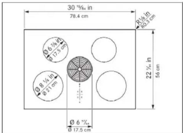
Fig. 5.1 Appliance dimensions top view
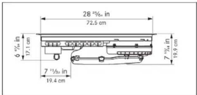
Fig. 5.2 Appliance dimensions front view
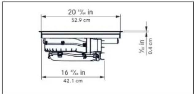
Fig. 5.3 Appliance dimensions side view
5.3 KCID936SBL
Parameter Value
| Supply voltage 240 V (208 V) | |
| Frequency 60 Hz | |
| Maximum power consumption 8.0 kW (6.9 kW) | |
| Fuse protection 40 A | |
| Dimensions 36 | ^11/_32 × 22^3/_64 × 7^53/_64 in, |
| 92.3 x 56 x 19.9 cm | |
Weight 46 lbs (20.9 kg)
Cooktop
| Surface material Glass ceramic | |
| Cooktop power levels 1 - 9, P | |
| Front left cooking zone size ∅ 8 | ^1/_4 in, ∅ 21 cm |
| Front left cooking zone output 2300 W | |
| Front left cooking zone power setting output | 3000 W |
| Rear left cooking zone size ∅ 6 | ^7/_8 in, ∅ 17.5 cm |
| Rear left cooking zone output 1400 W | |
| Rear left cooking zone power setting output | 2100 W |
| Front right cooking zone size 9 | ^1/_16 × 9^1/_16 in, 23 x 23 cm |
Front right cooking zone output 2100 W
| Front right cooking zone power set- 3000 W ting output | |
| Rear right cooking zone size 9 | ^1/_16 × 9^1/_16 in,23 x 23 cm |
| Rear right cooking zone output 2100 W | |
| Rear right cooking zone power set-ting output | 3000 W |
| Energy efficiency | EnergyStar certified |
| Exhaust air system | |
| Cooktop extractor power levels | 1 - 9, P |
| Airflow 332 cfm / sone at | 100 cfm 0.271 |
| Grease absorption rate | 98.2 % |
Tab. 5.2 Technical data for KCID936SBL
5.4 Appliance dimensions KCID936SBL
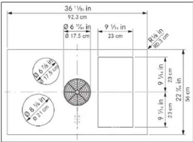
Fig. 5.4 Appliance dimensions top view
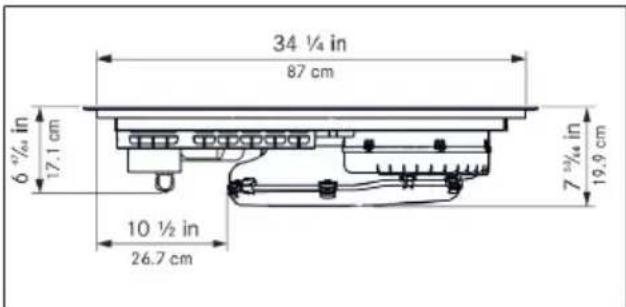
Fig. 5.5 Appliance dimensions front view
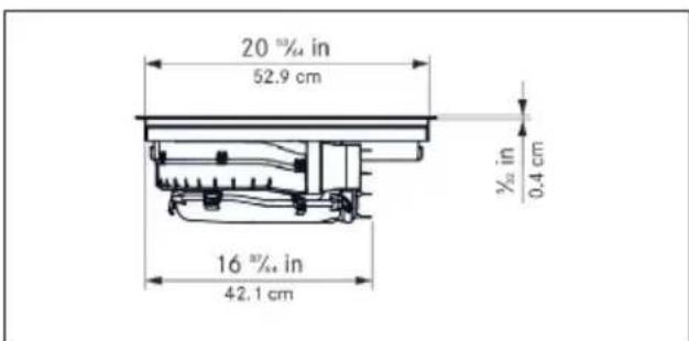
Fig. 5.6 Appliance dimensions side view
6 Appliance description
6.1 Model description
Model Long description
| KCID930SBL KitchenAid 30" Induction Downdraft Cooktop |
| KCID936SBL KitchenAid 36" Induction Downdraft Cooktop |
Tab. 6.1 Model description
6.2 System description
6.2.1 Structure
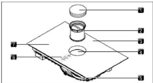
Fig. 6.1 Structure
[1] Air inlet nozzle
[2] Stainless steel grease filter
[3] Cooktop
[4] Inlet opening
[5] Fans
[6] Operating panel
[7] Cooking zone (x 4)
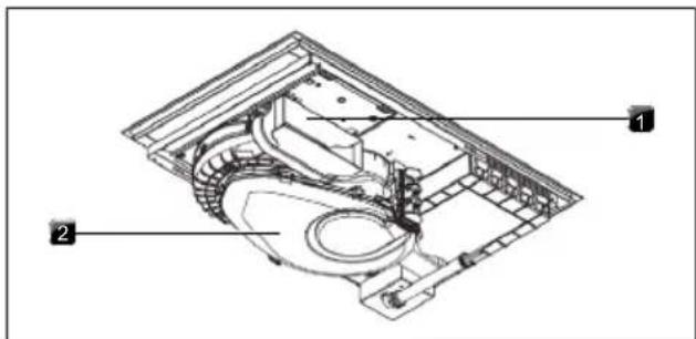
Fig. 6.2 Exhaust air variant rear view
[1] Exhaust opening
[2] Air guiding housing with housing base
6.2.2 Operating panel
The appliance is operated via a central touch operating panel.
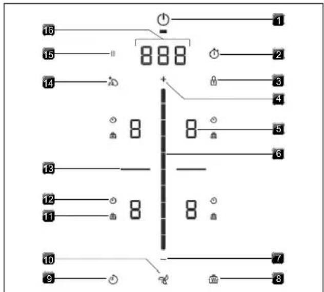
Fig. 6.3 Operating panel
[1] Power Button
[2] Timer Setting
[3] Control Lock
[4] Increase Setting Button
[5] Cooking Zone Indicator
[6] Control Slider
[7] Decrease Setting Button
[8] Heat Retention Button
[9] Active Zone Timer
[10] Fan
[11] Heat Retention Function Indicator
[12] Active Zone Timer Indicator
[13] Bridge XL Even- Heat Zone
[14] Control Lock Out For Cleaning
[15] Pause Button
[16] Control Display
6.2.3 7-segment display
Control display
| Indicator Meaning | |
| 1-9 | Power levels |
| P | Power setting |
| 0 | Inactive |
| A | Automatic extractor function |
| n | Automatic after-run |
| F | Filter service indicator |
| 000 | Time (minutes ^seconds ) |
| e.g. E | Error code |
Tab. 6.2 Meaning of the 7-segment displays
Cooking zone indicator
| Indicator Meaning | |
| 1-9 | Power level |
| P | Power setting |
| - | Melt |
| = | Keep Warm |
| = | Simmer |
| = | Pan size recognition |
| 0 | Inactive |
| H | Hot-Surface Indicator (cooking zone is switched off but still hot) |
| E | Error |
Tab. 6.3 Meaning of the 7-segment displays
6.2.4 Lighting
The appliance automatically adapts the display lighting to the current operating conditions. Unavailable functions are not shown and inactive functions are dimmed.
6.3 How the cooktop extractor works
The cooktop extractor is either operated as an exhaust air system or recirculation system.
Exhaust air operating mode
The cooking vapour is guided by the fan into the open air via the duct system.
Recirculation air operating mode
Optional accessories needed. The cooking steam is extracted by the fan and cleaned by a filter. The purified air is released back into the room.
6.4 How the induction cooktop works
Induction cooking zones heat the cookware via a magnetic field. The pot base is heated directly. The cooking zone is only heated indirectly. Cooking zones featuring induction technology only work with suitable cookware (magnetisable base with sufficient diameter).
Power levels
The high power output of induction cooktops results in the very quick heating up of cookware. In order to avoid burning food, slight adjustment is needed in comparison to conventional cooking systems when selecting the power level.
The specifications provided in the table are standard values. The power level should be adjusted according to the cookware and fill level.
| Power level Activity | |
| 1 | Melting butter and chocolate, breaking up gelatine |
| 1-3 | Keeping sauces and soups warm, soaking rice |
| 2-6 | Cooking potatoes, pasta, soups and ragouts, steaming fruit, vegetables and fish, defrosting food |
| 6-7 | Frying in coated pans, moderate frying (without overheating the fat) of pork cutlets or fish |
| 7-8 | Heating up fat, browning meat, cooking thickened sauces and soups, making omelettes |
| 9 | Bringing large amounts of liquid to the boil, searing steaks |
| P | Heating up water |
Tab. 6.4 Recommendations for power levels
Suitable cookware
Cookware with this symbol is suitable for induction cooktops.
▶ Observe the minimum cookware base diameter:
| Appliance Cooking zone Minimum cookware base diameter | |
| KCID930SBL Front 4 | ^23/_32 in (12 cm) |
| Rear 3 | ^35/_64 in (9 cm) |
| KCID936SBL Front left 4 | ^23/_32 in (12 cm) |
| Rear left 3 | ^35/_64 in (9 cm) |
| Front right 4 | ^23/_32 in (12 cm) |
| Rear right 4 | ^23/_32 in (12 cm) |
Tab. 6.5 Minimum cookware diameter
The heating and heat-through times and cooking results are significantly influenced by the structure and material of the cookware.
The cookware base must not be warped or have any sharp grooves or sharp edges. If the base is warped, the cookware may not be recognised or may overheat. Sharp grooves or edges may scratch the cooktop surface.
Noises
When operating induction cooktops, noises may occur due to material and processing of the cookware (humming, crackling, whistling, clicking or buzzing).
7 Functions and operation
The integrated cooktop extractor must not be used with other cooktops.
The appliance should only be operated when the filter replacement cover, stainless steel grease filter and air inlet nozzle are installed (as well as the activated charcoal filter in the recirculation model).
7.1 General operating instructions
The appliance is operated via a central touch operating panel. The operating panel is equipped with touch zones and display zones. Operate the appliance with your finger, touch controls and swipe gestures (slider operation).
7.2 Touch control
The system recognises different touch commands.
Touch commands Applicable to Time (contact)
| Tap Buttons + slider 0.3 s |
| Long press Buttons + slider 1-8 s |
| Swipe Slider 0.1-8 s |
Tab. 7.1 Touch control
7.3 Operating the system
7.3.1 Switch on/off
▶ Long press on the power button ⏻ Following start-up, the standard display will appear:
When the control lock is active, the control lock button lights up after system start 🔒.
7.3.2 Timer Setting
The Timer Setting emits both a visual and an acoustic signal after a set time (egg-timer function).
Activating the Timer Setting
▶ Tap the Timer Setting button Ⓞ The time entered is shown in the control display (☐).
Setting the time
▶ Set the desired time:
Command Selection in min/sec.
| Tap | ||
| Command Increase time Decrease time | ||
| Tap | + | - |
| Swipe | — — — upwards downwards | |
Tab. 7.2 Setting the time
Starting the Timer Setting
▶ Tap the Timer Setting button The set time starts to count down. The remaining time is shown on the control display.
Time lapsed
In the last 10 seconds of the countdown, the remaining time will flash and is displayed down to the second. When the time has lapsed, you will hear an acoustic signal.
Deactivating the Timer Setting early
▶ Long press on the Timer Setting button
7.4 Cooktop extractor functions
7.4.1 Fan power levels
The fan power levels can be adjusted in different ways:
by tapping or
▶ adjustment using the slider ---
by tapping a certain position on the slider
▶ long press on + or (adjustment in twos)
7.4.2 Fan power setting
When the power setting is activated, maximum extractor power is available for a predefined time. After 5 minutes, the power setting is automatically switched back to power level 9.
Activating the fan power setting
▶ Tap + when power level 9 is active.
• P appears in the fan display.
Deactivating the fan power setting
The fan power setting is deactivated early if another power level is set.
7.4.3 Automatic extractor function
After a brief delay, the extractor power is automatically adjusted to the highest power level used on all cooking zones that are currently in use.
- The automatic extractor function can be disabled manually at any time.
Function Power levels
| Cooking level 1 | 2 | 3 | 4 | 5 | 6 | 7 | 8 | 9 | P |
| Extractor power 4 4 4 4 5 6 7 8 9 P |
Tab. 7.3 Extractor power when automatic extractor function is active
Activating the automatic extractor function for a cooking session:
▶ tap the fan button %
- A is displayed.
Deactivating the automatic extractor function:
▶ Swipe to a fan power level.
or
▶ tap the fan button
7.4.4 Switching the fan off
▶ Swipe downwards to power level 0.
or
▶ tap until power level 0 is reached
or
▶ long press on the fan button %
- When the extractor is switched off, the automatic after-run function is activated.
- As soon as the automatic after-run stops, the cooktop extractor fan is switched off.
7.4.5 Automatic after-run
The cooktop extractor continues to run at a lower level and switches off automatically after a defined time. The duration of the after-run function can be set in the menu (factory setting is 20 minutes).
Switching off the automatic after-run early
▶ Long press on the fan button
We expressly recommends use of the cooktop extractor after-run function.
7.4.6 Filter service display
The cooktop extractor filter service display is automatically activated when the end of the activated charcoal filter service life is reached (only in recirculation mode).
- F is displayed in the control display.
- The cooktop extractor can still be operated without limitations.
7.5 Cooktop functions
7.5.1 Pot detection
On induction cooktops the cooking zone recognises the size of the cookware automatically and only targets the energy at that area. An induction cooking zone is not working if the display alternates between / U . Possible causes:
- Missing cookware
- Unsuitable cookware
- The base diameter of the cookware is too small. If no pot is detected 30 seconds after setting a power level, the cooking zone will switch off automatically.
Automatic Pot detection
The appliance automatically recognises cookware and activates the corresponding cooking zone controls. When no pot is detected the cooking zone indicator will not be shown. (Menu item 7: Auto Pot detection).
Do not simply rely on the pan size recognition function on induction cooktops; always switch the appliance off after use.
7.5.2 Selecting a cooking zone
▶ Tap a cooking zone display.
Cooking zone operation is activated and settings can be made until the operating panel switches to the standard display.
7.5.3 Setting cooking zone power levels
After selecting the cooking zone, the power level can be set in 3 different ways:
▶ by swiping until you reach the required power level or
▶ by tapping a certain position on the slider or
▶ by tapping + or . -
Repeat this process to operate further cooking zones if necessary.
The power level set is shown in the respective cooking zone display.
Five seconds after the power level is changed, the operating panel display automatically returns to the standard display.
7.5.4 Cooking zone power setting
When the power setting is activated, maximum cooking zone power is available for a cooking zone. After 5 minutes, the power setting is automatically switched back to power level 9. The maximum power is temporarily reduced for the second cooking zone on the same side. For rectangular surface induction cooking zones, the power is reduced to power level 7 and for round induction cooking zones to power level 8.
If the power setting is set too high for the second cooking zone, the power setting will be automatically reset to power level 9 for the other cooking zone.
Activating the power setting for a cooking zone
▶ Tap when power level 9 is active.
• P appears in the cooking zone display.
Deactivating the power setting early
▶ Setting another power level
Do not heat up oil, fat and the like on the power setting. The bottom of the pan can overheat due to the high power output.
7.5.5 Active Zone Timer
This automatic cut-off function automatically switches off the selected cooking zone once a preset time has lapsed. The aktive zone timer function can also be used on several cooking zones at the same time (multi-timer).
Activating cooking zone timers
Prerequisite: Cooking zone is active (power level is set).
▶ Tap the timer button
- The time entered is shown in the control display (☐)
Setting the time
▶ Set the desired time:
Command Selection in min/sec.
| Tap | ||
| Command Increase time Decrease time | ||
| Tap | + | - |
| Swipe | --- | --- |
Tab. 7.4 Setting the time
Starting the timer
▶ Tap the flashing timer button
The set time starts to count down. The remaining time is shown on the control display.
Showing the remaining time
Tap the cooking zone display with an active cooking zone timer.
- The remaining time is shown in the control display.
Changing active timers
Tap the cooking zone display with an active cooking zone timer.
▶ Tap the timer button
- The cooking zone timer is stopped.
- The remaining time flashes in the display.
▶ Change the set time and restart the cooking zone timer.
Multi-timer
▶ Repeat the process for additional cooking zones.
Switching the timer off early
Tap the cooking zone display with an active cooking zone timer.
▶ Long press on the timer button
Time lapsed
In the last 10 seconds of the countdown, the remaining time will flash and is displayed down to the second. At the end of the set time, an acoustic signal is heard and the cooking zone is automatically switched to power level 1.
7.5.6 Pause function
With the pause function all cooking zones can be quickly and easily deactivated temporarily. The cooking processes can be interrupted for a maximum of 10 seconds. If the pause function is deactivated, operation will resume with the original settings. Once 10 minutes have lapsed, the cooking session is automatically ended.
The fan function, the bridge function and the (active) minute minder cannot be interrupted. Active cooking zone timers are stopped.
Activating the pause function
▶ Tap the pause button
Deactivating the pause function
▶ Long press on the pause button
7.5.7 Variable heat retention function
You can choose from 3 heat retention levels according to the situation:
Heat retention level Symbol Temperature
| 1 (melting) ≈ 108°F (42°C)_ |
| 2 (keeping warm) ≈ 165°F (74°C) |
| 3 (simmering) ≈ 201°F (94°C) |
Tab. 7.5 Heat retention levels
In practice the temperatures of the heat retention levels may vary slightly as they are influenced by different factors.
This function is designed for use with cookware lids. To maintain the specified temperatures, a cookware lid must be used.
Activating the heat retention function
▶ Selecting a cooking zone
▶ Tap the heat retention button
Increasing or reducing the heat retention level
▶ Swipe to reach the required heat retention level or
▶ tap for until the required heat retention level is reached
▶ Tap the heat retention button to confirm.
Deactivating the heat retention function
▶ Tap the corresponding cooking zone display.
▶ Long press on the heat retention button
or
▶ swipe right down to the bottom (power level 0).
- The heat retention function is deactivated.
7.5.8 Bridge XL Even- Heat Zone
With the Bridge XL Even- Heat Zone function, two cooking zones located one behind the other can be combined to form one large cooking zone. The power for the combined zones is then adjusted by a single operating control. Power adjustment takes place simultaneously (both cooking zones are operated on the same power level). The Bridge XL Even- Heat Zone function is suitable for heating food, e.g. in a roaster.
If both cooking zones are active before the Bridge XL Even- Heat Zone function is activated, the lower power level is adopted. If timers are active on the cooking zones, the lower timer value will be adopted for the bridge timer.
The Bridge XL Even- Heat Zone function finishes and the cooking zones are deactivated if no suitable cookware is detected (pan size recognition) on any or only one of the two cooking zones for 10 seconds.
Activating the Bridge XL Even- Heat Zone function
▶ Tap the two cooking zone indicators that should be bridged.
- Both cooking zone displays show the same power level.
- Active additional cooking zone functions are adopted (dual display).
Deactivating the Bridge XL Even- Heat Zone function
▶ Tap the two cooking zone indicators for which you want to cancel the bridge function.
● The power levels are set to 0.
- If a cooking zone timer was active, it is deactivated.
7.5.9 Automatic bridge function
If a large enough piece of cookware is placed on the two cooking zones that are one behind the other, they will automatically be combined to form one large cooking zone.
If the permanent pan size recognition function is switched on (Menu item 7: Auto Pot detection), the automatic bridge function is also activated.
7.5.10 Switching off the cooking zone
▶ Selecting a cooking zone
▶ Set power level to 0
or
▶ long press on the cooking zone display
7.6 Features
7.6.1 Control Lock
The operation lock can be used to avoid unintentional operation of the appliance. If the control lock is active, the control lock button 🔒 will light up in the operating panel display.
Permanently activating/deactivating the control lock
see "8.2 Menu item 2: Control Lock"
Deactivating the control lock for a cooking session
▶ Long press on the control lock button
7.6.2 Control lock out for cleaning
The control lock out for cleaning function blocks the operating panel. If no wiping motions are detected on the operating panel, the control lock out for cleaning function will automatically deactivate after 5 seconds.
Activating the control lock out for cleaning function
▶ Tap the control lock out for cleaning button
Prematurely deactivating the control lock out for cleaning function
▶ long press on the control lock out for cleaning button
7.6.3 Heat retention function indicator
If a cooking zone is still hot after switching off, H is displayed.
▶ Do not touch hot cooking zones.
▶ Do not place any objects on the cooking zones while hot.
The display goes out after a sufficient cooling time (temperature < 131 °F (55 °C)).
7.6.4 Shut-down
Cooktop extractor
The cooktop extractor switches to automatic mode after 120 min if there has been no input or changes to the power level.
7.6.5 Overheat control
In the event of overheating, the cooktop power is reduced or the appliance is switched off completely. The overheating control is triggered when:
• cookware is heated up empty;
- oil or fat is heated on high power;
- a hot cooking zone is switched on again after a power cut.
Whilst the overheating control is active, one of the following steps is taken:
- the activated power setting is switched back to the previous level;
- the power setting can no longer be activated;
- the set power level is reduced;
● the cooktop switches off completely.
After a sufficient cooling period, the cooktop can be used again in full.
8 User menu
Calling up the user menu
Prerequisite: the appliance is switched on, all cooking zones and the cooktop extractor are inactive and there is no residual heat.
▶ Long press on the control display.
Navigating the user menu
Navigate to the next menu item:
▶ Tap the control display.
- Any changed settings are automatically applied when changing to another menu item or when exiting the menu.
Closing the user menu
▶ Long press on the control display.
or
▶ long press on the power button
- The menu is closed and the appliance is switched off.
User menu overview
| Menu item/Description/Selection Factory setting | |
| 1 Volume of the acoustic signals (0-9) 4 | |
| 2 Lock (On/Off) Off | |
| 3 Show filter status (reset filter service display) | |
| 4 Duration of the automatic after-run function (10, 15, 20 min.) | 20 min |
| 5 Touch zone reaction speed (1 slow, 2 medium, 3 fast) | 2 |
| 6 LED test | |
| 7 Permanent pan size recognition On | |
| 8 Software/hardware version | |
| A Super simple mode Off | |
| 0 Reset to factory settings | |
Tab. 8.1 User menu overview
8.1 Menu item 1: Volume of the acoustic signals
It is possible to set different acoustic signal volume levels. This does not apply to relevant acoustic signals.
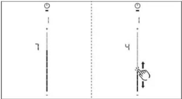
Fig. 8.1 Menu item 1: volume of the acoustic signals
8.1.1 Sounds
The system distinguishes between different signal acoustic signals:
Acoustic signal Purpose
| Short beep (0.25 s) Confirmation of a selection |
| Sequence of beeps Interaction required |
Tab. 8.2 Sounds
8.2 Menu item 2: Control Lock
The Control Lock can be permanently activated or deactivated.
▶ Tap the top slider segment to activate.
▶ Tap the bottom slider segment to deactivate.
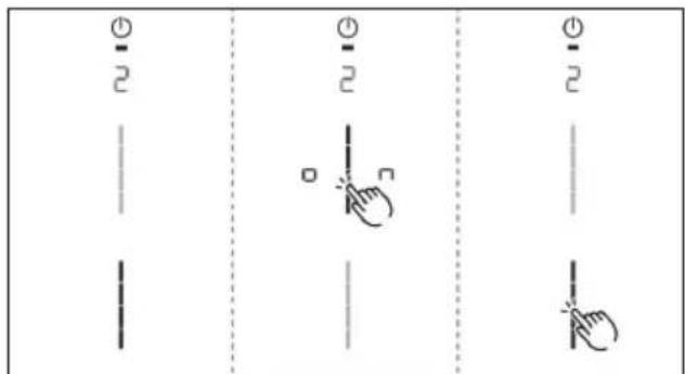
Fig. 8.2 Menu item 2: Control Lock
8.3 Menu item 3: Show filter status and reset filter service display
If menu item 3 is called up, the filter status will be automatically shown (only in recirculation mode).
Resetting the filter service display:
▶ Long press on the fan button
- The filter status will be reset to 100%.
- The filter service display F will no longer be shown when switching on.
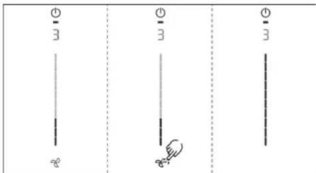
Fig. 8.3 Menu item 3: Reset filter status and the filter service display
8.4 Menu item 4: Duration of the automatic after-run function
If menu item 4 is called up, the currently set duration will be shown for 2 seconds.
There are three times to choose from:
20 minutes / 15 minutes / 10 minutes
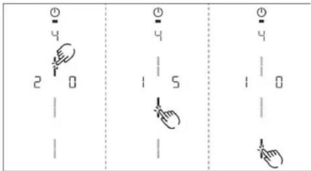
Fig. 8.4 Menu item 4: Selecting the duration of the automatic after-run function
8.5 Menu item 5: Touch zone reaction speed
If menu item 5 is called up, the currently set reaction speed will be shown.
- Reaction speed1: slow
- Reaction speed 2 medium
- Reaction speed ∃fast
Selecting the reaction speed:
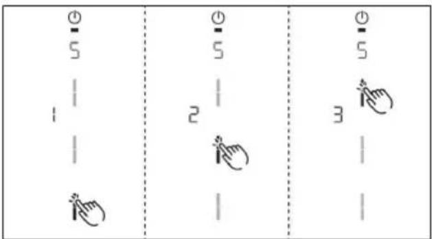
Fig. 8.5 Menu item 5: Reaction speed
8.6 Menu item 6: LED test
i Function inspection of all LEDs in the touch zones.
Starting the LED test:
▶ Tap the slider zone
- All indicators are displayed at 50 % brightness.
Tap any indicator you wish.
- The selected indicator will be displayed at 100% brightness for 1 second for testing purposes.
- Any other indicators can be tested by touch.

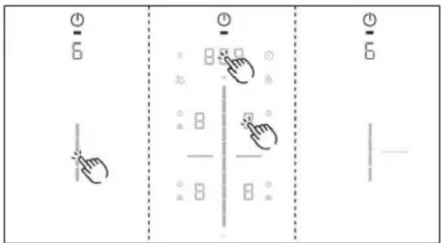
Fig. 8.6 Menu item 6: LED test
Ending the LED test:
▶ Long press on the control display.
The LED test will be automatically ended when there has been no activity for 5 seconds.
8.7 Menu item 7: Pan Size Detection
Switch Pan Size Detection permanently on or off.
Activate or deactivate Pan Size Detection:
▶ Tap the top slider segment to activate.
▶ Tap the bottom slider segment to deactivate.
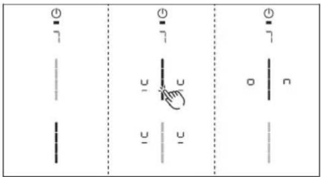
Fig. 8.7 Menu item 7: Pan Size Detection
8.8 Menu item 8: Show software/hardware version
The software/hardware version is shown via the four 4 cooking zones indicators.
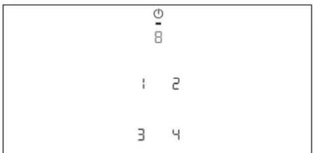
Fig. 8.8 Menu item 8: Software/hardware version
8.9 Menu item A: Super simple mode
The following additional functions and their indicator are deactivated in the super simple mode:
- Cooking zone timer
- Short-time timer
- Cleaning lock
- Operating lock
- Heat retention function
- Pause function
Activating or deactivating super simple mode:
▶ Tap the top slider segment to activate.
Tap the bottom slider segment to deactivate
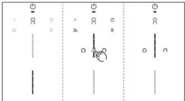
Fig. 8.9 Menu item A: Super simple mode
8.10 Menu item 0: Reset to factory settings
i Menu item 0 enables all settings in the user menu to be reset to the factory settings.
Resetting to factory settings
▶ Long press on the slider zone
- After resetting, the appliance is switched off.
9 Cleaning and maintenance
IMPORTANT: When conducting cleaning and maintenance, ensure that the cooktop and cooktop extractor are fully switched off and cooled.
▶ Adhere to the following cleaning and maintenance cycles:
Component Cleaning cycles
| Operating panel Immediately after every soiling | |
| Cooktop Clean well immediately after soiling, using conventional detergents | |
| Cooktop extractor Weekly | |
| Air inlet nozzle and stainless steel grease filter | After cooking very greasy dishesat least once a weekby hand or in the dishwasher (at 149 °F (65°C) max.)Clean the stainless steel surfaces in the polishing direction only |
| Air guiding housing | Every 6 months |
| Activated charcoal filter (with recirculation only) | Replace if odours have built up, extraction power is dwindling or filter service indicator F appears |
Tab. 9.1 Cleaning cycles
i Regular cleaning and maintenance ensures long service life of the product and optimal function.
9.1 Cleaning agents
▶ Do not use any chemically aggressive cleaning agents or agents containing acid or lye (e.g. oven spray).
▶ Make sure that the cleaning agent does not contain any sand, soda, acids, lyes or chloride.
▶ Do not use a steam cleaner, abrasive sponges or scouring pads.
Aggressive cleaning agents and abrasion caused by the pot bases will damage the surface and dark stains will occur.
9.2 Maintenance
▶ Do not use the cooktop as a work or storage surface.
▶ Do not push or pull cookware over the cooktop.
Any changes in colour or glossy spots do not mean that the cooktop is damaged. They do not affect the functionality of the cooktop or the stability of the glass ceramic panel.
Changes in the colour of the cooktop are the result of residues which have not been removed and have burnt on.
Glossy spots are the result of wear by the pan base, especially if aluminium-based cookware or unsuitable cleaning agents are used. These are difficult to remove.
9.3 Cleaning the cooktop
To clean the cooktop, you need a special glass ceramic scraper and suitable cleaning agents.
Scheduled cleaning
▶ Remove all coarse dirt and food residues from the cooktop using a glass ceramic scraper.
▶ Apply the cleaning agent to the cold cooktop.
▶ Spread the cleaning agent using kitchen roll or a clean cloth.
▶ Wipe the cooktop clean with a damp cloth.
▶ Dry the cooktop with a clean cloth.
Heavy soiling
Remove heavy soiling and marks (limescale marks, mother-of-pearl-like shiny marks) using cleaning products while the cooktop is still warm.
▶ Wipe off any food that boils over with a damp cloth.
▶ Remove any remaining dirt with the glass ceramic scraper.
Surface cleaning during operation
▶ Always remove any seeds, crumbs or similar immediately to avoid scratching the surface.
Remove stubborn residues of plastic, aluminium foil, sugar or sweet dishes from the hot cooking zone immediately using a glass ceramic scraper to avoid burning.
9.4 Cleaning the cooktop extractor
▶ Clean the surfaces of the extraction system using a soft, damp cloth, detergent or a mild window cleaning agent.
▶ Soften dried on dirt using a damp cloth (do not scrape it off!).
9.4.1 Cleaning the air inlet nozzle and stainless steel grease filter
▶ Remove the components
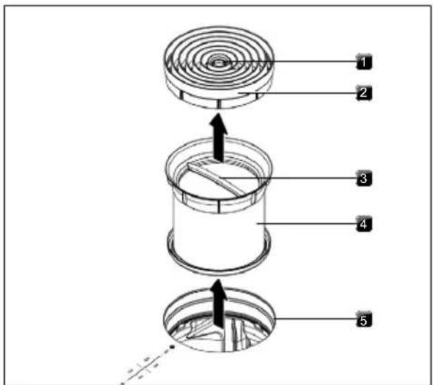
Fig. 9.1 Removing the components
[1] Access opening
[2] Air inlet nozzle
[3] Handle
[4] Stainless steel grease filter
[5] Inlet opening
Manual cleaning
▶ Use a cleaner and degreaser in one.
▶ Rinse the components with hot water.
▶ Clean the components with a soft brush.
▶ Rinse the components in clean water after cleaning.
Cleaning in the dishwasher
Place the components in the dishwasher in such a way that water cannot accumulate inside them.
▶ Select a rinse programme with a maximum temperature of 149 °F ( 65 °C ).
The stainless steel grease filter W11751832 must be replaced when it can no longer be fully cleaned. (Warranty, technical service, spare parts, accessories).
Fitting the components
▶ To install the components, follow the steps in reverse order.
Only insert dry, clean components inside the appliance.
9.4.2 Removing liquids from the appliance
Any liquids that flow into the appliance through the inlet opening are caught by the stainless steel grease filter (up to 5.1 oz [150 ml]) and in the air guiding housing.
Do the following:
Remove the air inlet nozzle and stainless steel grease filter.
▶ Empty the stainless steel grease filter.
▶ Check whether any liquid has gathered in the base of the air guiding housing.
▶ Remove the liquid from the air guiding housing.
▶ To dry the activated charcoal filter and duct parts, switch on the cooktop extractor at a minimum power level of 5.
- After 120 minutes, the cooktop extractor will automatically switch off and the automatic after-run function will be activated.
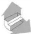
9.5 Cleaning the air guiding housing
The air guiding housing can be found on the bottom of the cooktop inside the floor unit. Grease particles and limescale residues can settle on the surface of the air guiding housing.
Opening the air guiding housing
▶ Remove the air inlet nozzle and stainless steel grease filter.
▶ Remove the filter replacement cover.
▶ Release the 6 locks around the edge of the base.
▶ Remove the housing base.
▶ Clean the air guiding housing and the housing base with a mild cleaning agent.
natural_image
Technical diagram of a mechanical assembly with labeled components (no readable text or symbols)Fig. 9.2 Air guiding housing
[1] Spigot
[2] Sealing groove
[3] Lock
[4] Housing base
[5] Air guiding housing
Closing the air guiding housing
▶ Position the housing base with the help of the 3 spigots around the edges.
▶ Push the housing base upwards into the sealing groove.
▶ Close the 6 locks.
▶ Check that the housing base is positioned correctly.
▶ Insert the filter replacement cover.
▶ Check that the filter replacement cover is positioned correctly.
▶ Insert the stainless steel grease filter and the air inlet nozzle.
10 Troubleshooting
WARNING

Electrical Shock Hazard
Disconnect power before servicing Failure to do so could result in death or electrical shock.
You can often remedy faults and errors yourself. This saves time and money as you don't need to call out customer services.
Operating situation Cause Remedy
| Appliance cannot be switched on Fuse/automatic circuit breaker defective | Replace the fuse;Switch the automatic circuit breaker back on | |
| The fuse/automatic circuit breaker trips several times | Contact the Service Team | |
| The power supply is disconnected Have a specialist electrician inspect the power supply | ||
| Odour formation when operating a new appliance | This is normal with brand new appliances | Odours stop forming after a few operating hours |
| A cooking zone display shows | No or unsuitable cookware Use suitable, appropriately sized cookware (see “Appliance description”) | |
| The control lock button lights up | Active control lock deactivate the control lock | |
| Cooking zone/cooktop switches off automatically | The maximum cooking zone operating time has been exceeded | Put the cooking zone back into operation |
| Power setting prematurely cancelled The | overheating control has tripped | see "7.6.5 Overheat control" |
| The cooktop cooling fan continues to run when the cooktop has been switched off | The cooling fan runs until the cooktop has cooled | Wait until the cooling fan switches off automatically |
| Decreased extraction performance of the cooktop extractor | Grease filter extremely dirty Clean or replace the grease filter | |
| Activated charcoal filter extremely dirty (recirculation only) | Replace the activated charcoal filter | |
| Item in air guiding housing (e.g. cleaning cloth) | Remove the object | |
| Eis displayed | Use of a phase-separating window contact switch | Open the window |
| Fan defective or a duct connection has become loose | Contact the service team | |
| E2is displayed | The overheating control has tripped | see "7.6.5 Overheat control" |
| E90,E91,E92,E93played | Faulty connectivity module Contact the service team | |
| Fis shown (recirculation only) | End of activated charcoal filter service life reached | Insert a new activated charcoal filter (Replace the activated charcoal filter). |
Tab. 10.1 Troubleshooting
11 Installation
WARNING

Electrical Shock Hazard
Disconnect power before servicing
Failure to do so could result in death or electrical shock.
WARNING
Excessive Weight Hazard
Use two or more people to move and install or uninstall appliance.
Failure to do so can result in back or other injury. The silicone must cure for 24 hours before using the appliance for the first time.
11.1 General installation instructions
The appliance must not be installed above cooling devices, dishwashers, stoves, ovens, washing machines or dryers.
The contact surfaces of the worktops and wall sealing strips must be made of a heat-resistant material (up to approx. 212 °F (100 °C)).
Worktop cut-outs must be moisture-sealed using suitable means and, where necessary, fitted with a thermal insulator.
The integrated cooktop extractor must not be used with other cooktops.
To maintain the level of performance and avoid overheating, sufficient ventilation must be ensured below the cooktops.
If cable guard floor (false floor) is planned beneath the appliance, this must be fitted so it does not obstruct ventilation.
The rating label can be found on the underside of the appliance on the black enclosure.
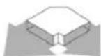
11.1.1 Simultaneous operation of the cooktop extractor in the exhaust air mode with a fireplace dependent upon the air supply in the room
Fireplaces that depend on the air in the room (e.g. gas, oil, wood or coal-fired heaters, continuous-flow water heaters, instantaneous water heaters) draw in air from the room in which they are installed and release the exhaust fumes into the outside air via an exhaust system (e.g. chimney).
If the cooktop extractor is used in exhaust air mode, it draws in air from the room in which it is installed as well as from neighbouring rooms. Without sufficient air, there will be a drop in air pressure. Gases could be drawn out of the chimney or extraction ducting and back into the room.
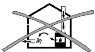
natural_image
Diagram of a house with crossed beams and directional arrows indicating airflow or ventilation (no text or symbols)Fig. 11.1 Exhaust air installation – not permitted
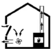
natural_image
Simple line drawing of a house with airflow and a chimney, no text or symbols presentFig. 11.2 Exhaust air installation – correct
▶ If simultaneously operating both the cooktop with a fireplace and the cooktop extractor in the room they are installed, ensure that...
• ...the maximum low pressure is 4 Pa;
- ...a device (e.g. window contact switch, low pressure warning device) is used to ensure that a sufficient supply of fresh air is guaranteed;
- ...the exhaust air is not channelled into a chimney that is used for exhaust gases of appliances operated with gas or other combustibles;
- ...the installation is checked and approved by an authorised certified engineer (e.g. HVAC technician for NAR).
If the cooktop extractor is used exclusively in recirculation mode, simultaneous operation with a fireplace dependent on the air in the room is possible without any additional measures.
11.2 Scope of delivery
Scope of delivery Quantity
| Cooktop with integrated cooktop extractor 1 |
| Air inlet nozzle 1 |
| Stainless steel grease filter 1 |
| Operating and installation instructions 1 |
| Tech sheet 1 |
| Mounting brackets 3 |
| Sealing tape 1 |
| Height adjustment plate set 1 |
Tab. 11.1 Scope of delivery
Checking the scope of delivery
▶ Make sure the delivery is complete and check it for damage.
▶ Immediately notify the Service Team if parts are missing or damaged.
▶ Do not under any circumstances install parts which are damaged.
▶ Dispose of transport packaging in the proper manner (Decommissioning, disassembly and disposal).
11.3 Tools and aids
The following tool, among others, is required to correctly install the appliance:
• size 20 Torx screwdriver key
- black, heat-resistant silicone sealant
11.4 Assembly instructions
11.4.1 Installation clearances
▶ Observe the required clearance around the worktop cut-out.
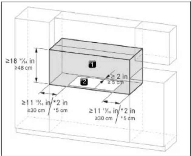
Fig. 11.3 Required clearance
[*] if installed in canada
[1] Required clearance
[2] Worktop cut-out
A minimum side clearance of 6" (15.2 cm) is recommended between side of cooktop and side wall for maximum ventilation performance.
11.4.2 Information on kitchen units
- Cross bars on the kitchen unit in the area of the worktop cut-out may need to be removed.
- In the case of thin worktops, there must be a sufficiently rigid support plate on the unit.
- The drawers and/or shelves in the floor unit must be removable.
- The drawers of the floor unit must be shortened depending on the installation situation.
If false floor (cable guard floor) is planned, the following must be taken into account:
- It must be fitted in such a way that it can be removed from below for maintenance work.
- To ensure sufficient cooktop ventilation, a minimum distance of ^19 / _32 in (1.5 cm) to the bottom edge of the cooktop is to be observed.
11.5 Worktop cut-out
The minimum measurement of 2 in (5.1 cm) from the front edge of the worktop to the worktop cut-out is a recommendation.
▶ Create the worktop cut-out taking into account the specified cut-out dimensions.
▶ Make sure that the cut surfaces of the worktops are properly sealed.
▶ Comply with the instructions of the worktop manufacturer.

After making the countertop cutout, some installations may require notching down the base cabinet side walls to clear the cooktop base. To avoid this modification, use a base cabinet with sidewalls wider than the cutout.
11.5.1 Cut-out dimensions for flush installation (30")
KCID930SBL
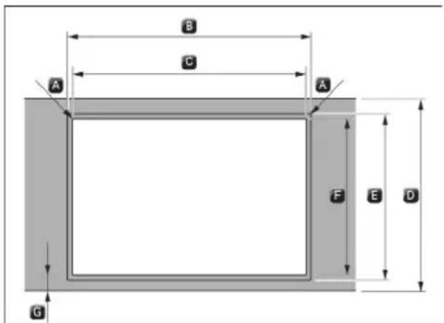
Fig. 11.4 Cut-out dimensions for flush installation
$$ \begin{array}{l} A R 0. 2 \text { in } [ R 0. 5 \mathrm{cm} ] \ B 3 1 \quad {} ^ {1} / _ {3 2} \pm 0. 0 8 \text { in } [ 7 8. 8 \pm 0. 2 \mathrm{cm} ] \ C 2 8 \quad^ {5 5} / _ {6 5} \pm 0. 0 8 \text { in } [ 7 3. 3 \pm 0. 2 \mathrm{cm} ] \ D \geq 2 3 ^ {5} / _ {8} \text { in } [ \geq 6 0 \mathrm{cm} ] \ E 2 2 \quad^ {7} / _ {3 2} \pm 0. 0 8 \text { in } [ 5 6. 4 \pm 0. 2 \mathrm{cm} ] \ F 2 1 \quad {} ^ {5} / _ {3 2} \pm 0. 0 8 \text { in } [ 5 3. 7 \pm 0. 2 \mathrm{cm} ] \ G \geq 2 \text { in } [ \geq 5 \mathrm{cm} ] \ \end{array} $$
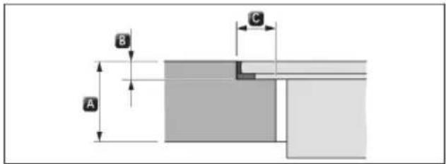
Fig. 11.5 Rebate dimensions for flush installation
$$ \begin{array}{l} A ^ {2 5} / _ {6 4} - 1 ^ {3 7} / _ {6 4} \text { in } [ 1 - 4 \mathrm{cm} ] \ B ^ {9} / _ {3 2} + ^ {1} / _ {6 4} \text { in } [ 0. 7 + 0. 0 5 \mathrm{cm} ] \ C ^ {1 5} / _ {3 2} \text { in } [ 1. 2 \mathrm{cm} ] \ \end{array} $$
11.5.2 Cut-out dimensions for surface mounting (30")
KCID930SBL
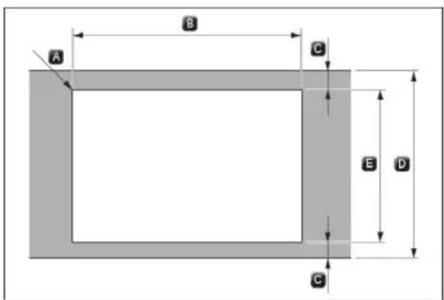
Fig. 11.6 Cut-out dimensions for surface mounting
$$ \begin{array}{l} A R 0. 2 \text { in } [ R 0. 5 \mathrm{cm} ] \ B 2 8 \quad^ {5 5} / _ {6 5} \pm 0. 0 8 \text { in } [ 7 3. 3 \pm 0. 2 \mathrm{cm} ] \ C \geq 2 \text { in } [ \geq 5 \mathrm{cm} ] \ D \geq 2 3 ^ {5} / _ {8} \text { in } [ \geq 6 0 \mathrm{cm} ] \ E 2 1 \quad {} ^ {5} / _ {3 2} \pm 0. 0 8 \text { in } [ 5 3. 7 \pm 0. 2 \mathrm{cm} ] \ \end{array} $$
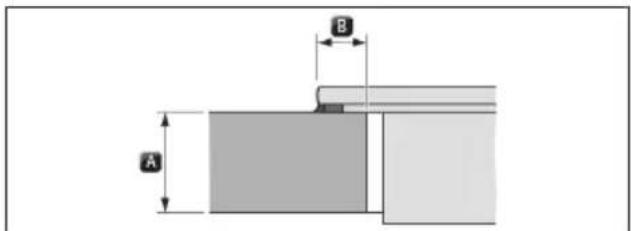
Fig. 11.7 Overlay dimensions for surface mounting
$$ \begin{array}{l} A \quad {} ^ {2 5} / _ {6 4} - 1 ^ {3 7} / _ {6 4} \text { in } [ 1 - 4 \mathrm{cm} ] \ B ^ {2 5} / _ {6 4} \text { in } [ 1 \mathrm{cm} ] \ \end{array} $$
11.5.3 Cut-out dimensions for flush installation (36")
KCID936SBL
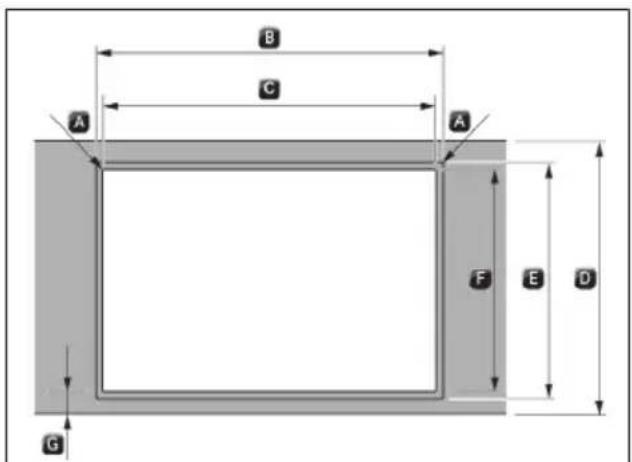
Fig. 11.8 Cut-out dimensions for flush installation
A R0.2 in [R0.5 cm]
B 36 ^1/_2 ± 0.08 in [92.7 ± 0.2 cm]
C 34 ^9 / _16 ± 0.08 in [87.8 ± 0.2 cm]
D ≥ 23 ^5/_8 in [≥ 60 cm]
E 22 132 ± 0.08 in [56.4 ± 0.2 cm]
F 21 ^5/_32 ± 0.08 in [53.7 ± 0.2 cm]
G ≥ 2 in [≥ 5 cm]
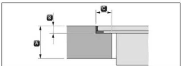
Fig. 11.9 Rebate dimensions for flush installation
A ^25/64-1^37/64 in [1 - 4 cm]
B ^9/32 + ^1/64 in [0.7 + 0.05 cm]
C ^15/_32 in [1.2 cm]
11.5.4 Cut-out dimensions for surface mounting (36")
KCID936SBL
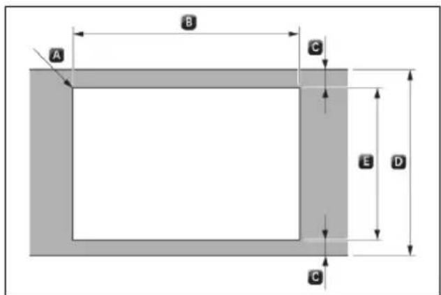
Fig. 11.10 Cut-out dimensions for surface mounting
A R0.2 in [R0.5 cm]
B 34 ^9/_16 ± 0.08 in [87.8 ± 0.2 cm]
C ≥ 2 in [≥ 5 cm]
D ≥ 23 ^5/_8 in [≥ 60 cm]
E 21 ^5/_32 ± 0.08 in [53.7 ± 0.2 cm]
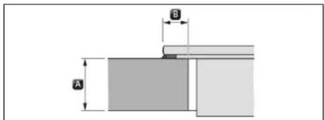
Fig. 11.11 Overlay dimensions for surface mounting
A ^25/64-1^37/64 in [1-4 cm]
B ^25/_64 in [1 cm]
11.6 Electrical Requirements
WARNING

Electrical Shock Hazard
Disconnect power before servicing.
Use 10 gauge copper wire.
Electrically ground cooktop.
Failure to follow these instructions can result in death, fire, or electrical shock.
IMPORTANT: The cooktop must be electrically grounded in accordance with local codes and ordinances, or in the absence of local codes, with the National Electrical Code, ANSI/NFPA 70 or Canadian Electrical Code, CSA C22.1
If codes permit and a separate ground wire is used, it is recommended that a qualified electrical installer determine that the ground path is adequate
A copy of the above code standards can be obtained from: National Fire Protection Association
1 Batterymarch Park
Quincy, MA 02169-7471
CSA International 8501
East Pleasant Valley Road
Cleveland, Ohio 44131-5575
A 208/240 VAC, 60 Hz, 40 A, fused electrical circuit is required. A time-delay fuse or circuit breaker is also recommended. It is recommended that a separate circuit serving only this cooktop be provided.
Electronic systems operate within wide voltage limits, but proper grounding and polarity are necessary. Check that the outlet provides a minimum of 208 V power and is correctly grounded.
The wiring diagrams are provided with this cooktop. See “Wiring Diagrams” on a separate sheet. The wiring diagrams are located on the underside of the cooktop base.
This cooktop is not required to be plugged into a GFCI-(Ground-Fault Circuit Interrupter) outlet or AFCI-(Arc Fault Circuit Interrupter) type circuit breaker. It is
recommended that you not plug an cooktop or any other major appliance into a GFCI wall outlet or an AFCI type circuit breaker as it may cause these types of circuit breakers to trip during normal cycling.
Performance of this cooktop will not be affected if operated on a GFCI/AFCI-protected circuit. However, occasional nuisance tripping of the GFCI breaker is possible due to the normal operating nature of electronic cooktops
11.7 Installing the appliance in exhaust air mode
National and regional laws and regulations must be observed with regard to the exhaust duct design.
A sufficient air supply must be ensured.
The exhaust air must be directed to the outside by appropriate exhaust air ducts.
The minimum cross section of the exhaust air duct must be 28 in ^2 [176 cm ^2 ] which equates to a round pipe with a diameter of 6 in [15 cm].
▶ Do not terminate the vent system in an attic or other enclosed area.
▶ Use a venting cap.
The venting system must lead to the outside.
Before making cutouts, make sure there is proper clearance within the wall or floor for the exhaust vent.
▶ Do not cut a joist or stud unless absolutely necessary. If a joist or stud must be cut, then a supporting frame must be constructed.
The size of the vent should be uniform.
The vent system must have a damper.
▶ Use vent clamps to seal all joints in the vent system.
▶ Use caulking to seal exterior wall or roof opening around the cap.
▶ Determine which venting method is best for your application.
11.8 Preparing the appliance
Attaching the sealing tape
In the case of surface mounting, attach the enclosed sealing tape around the outer edges of the underside of the cooktop. Do not leave any gaps.
In the case of flush installation, attach the sealing tape to the contact surfaces in the worktop cut-out, even if you are sealing the cooktop with a silicone sealing compound or similar.
Fig. 11.12 Sealing tape in the case of surface mounting
[1] Silicone sealant
[2] Sealing tape
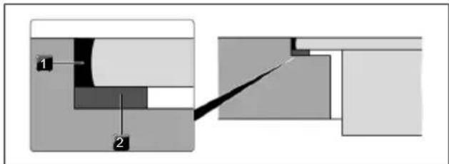
Fig. 11.13 Sealing tape in the case of flush installation
[1] Silicone sealant
[2] Sealing tape
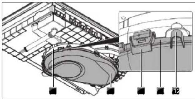
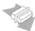
Fitting the mounting brackets
▶ Push 3 mounting brackets onto the cooktop.
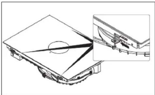
natural_image
Technical line drawing of a mechanical assembly with an inset showing a close-up of a component detail (no text or symbols present)Fig. 11.14 Fitting the mounting brackets
Mounting brackets slots are on the front and on the rear of the device.
▶ Hook the tab into the opening.
▶ Slide the mounting bracket into the slot to lock it in place.
▶ Fix the screw to the kitchen worktop.
11.9 Installation dimensions
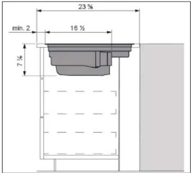
Fig. 11.15 Installation dimensions for exhaust air, worktop depth 23^ / s'' [60 cm]
11.10 Installing the cooktop
WARNING
Excessive Weight Hazard
Use two or more people to move and install or uninstall appliance.
Failure to do so can result in back or other injury. The silicone must cure for 24 hours before using the appliance for the first time.
11.10.1 Inserting the cooktop
▶ Before inserting the cooktop, remove the air inlet nozzle and the stainless steel grease filter
▶ Use the inlet opening as a handle during insertion.
▶ Keep the cooktop straight as you lift it into the worktop cut-out.
▶ Insert the cooktop into the centre of the worktop cut-out.
▶ Precisely align the cooktop.
Height adjustment plates for flush installation (optional)
To prevent slipping, the height adjustment plates are self-adhesive.
▶ If applicable, insert the height adjustment plates.
▶ Place the height adjustment plates next to the sealing tape.
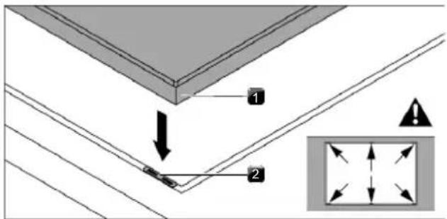
Fig. 11.16 Positioning the height adjustment plates
[1] Cooktop
[2] Height adjustment plate
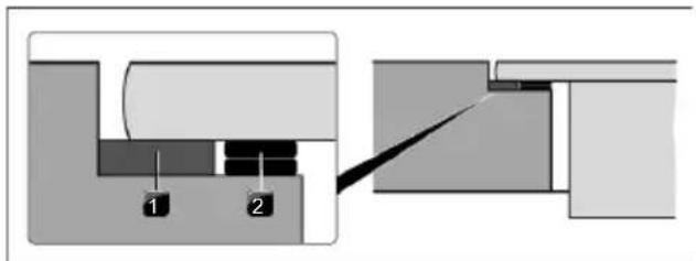
Fig. 11.17 Height adjustment plates
[1] Sealing tape
[2] Height adjustment plate
11.10.2 Securing the cooktop
Secure the cooktop to the worktop with the fixing bracket on the mounting brackets.
Tightening torque: max. 20 lbf in (2.2 Nm).

Do not use a powered screwdriver for installation, only hand screwdrivers.
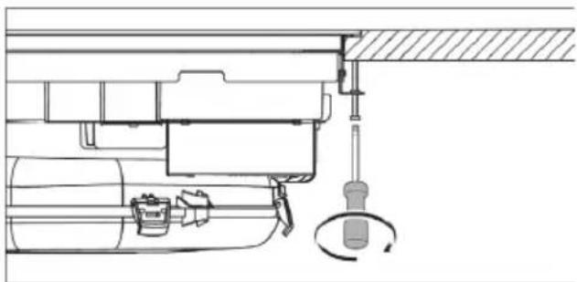
natural_image
Technical line drawing of a mechanical assembly with no visible text or symbolsFig. 11.18 Securing the cooktop
11.11 Vent System
11.11.1 Venting Requirements
IMPORTANT: This cooktop must be exhausted outdoors unless using the Duct-Free Filter Accessory Kit. See the "Venting Methods" section.
- Do not terminate the vent system in an attic, wall, a ceiling, or a concealed space of a building.
- Use a vent cap.
- Vent system must terminate to the outside.
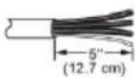
- Use only a 6" (15.2 cm) diameter round or 31/4" x 10" (8.3 cm x 25.4 cm) rectangular vent except as follows: For electric cooktops, a 5" (12.7 cm) diameter round vent may be used for venting straight out the back of the cooktop and directly through the wall for 10 ft (3.0 m) or less.
- Before making cutouts, make sure there is proper clearance within the wall or floor for the exhaust vent.
- Do not cut a joist or stud unless absolutely necessary. If a joist or stud must be cut, then a supporting frame must be constructed.
- The size of the vent should be uniform.
• The vent system must have a damper.
• Use vent clamps to seal all joints in the vent system. - Use caulking to seal exterior wall or roof opening around the cap.
- Determine which venting method is best for your application.
For Best Performance:
- Use 26-gauge minimum galvanized or 25-gauge minimum aluminum metal vent. Poor quality pipe fittings can reduce airflow. Flexible metal vent is not recommended.
NOTE: Local codes may require a heavier gauge material.
- Metal duct may be reduced to 30-gauge galvanized steel or 26-gauge aluminized steel if allowed by local codes. This reduction is based on information in the International Residential Codes Section M1601.1 (2006 edition).
- Do not install 2 elbows together.
- Use no more than three 90^ elbows.
- If an elbow is used, install it as far away as possible from the vent motor exhaust opening.
-
Make sure there is a minimum of 18" (45.7 cm) of straight vent between the elbows if more than one elbow is used.
-
Elbows too close together can cause excess turbulence that reduces airflow.
- Do not use a 5" (12.7 cm) elbow in a 6" (15.2 cm) or 31/4" x 10" (8.3 cm x 25.4 cm) system.
- Do not reduce to a 5" (12.7 cm) system after using 6" (15.2 cm) or 31/4" x 10" (8.3 cm x 25.4 cm) fittings.
- Avoid forming handmade crimps. Handmade crimps may restrict airflow.
- Use a vent cap for proper performance. If an alternate wall or roof cap is used, be certain the cap size is not reduced and that it has a backdraft damper.
- Use vent clamps to seal all joints in the vent system.
- Use caulking to seal exterior wall or roof opening around the cap.
The length of vent system and number of elbows should be kept to a minimum to provide efficient performance. The maximum equivalent length of the vent system is 60 ft (18.3 m). For altitudes above 4,500 ft (1372 m), reduce recommended vent run by 20% for best performance.
Cold Weather Installations
An additional backdraft damper should be installed to minimize backward cold air flow.
Makeup Air
Local building codes may require the use of makeup air systems when using ventilation systems greater than specified CFM of air movement. The specified CFM varies from locale to locale. Consult your HVAC professional for specific requirements in your area.
11.11.2 Concrete Slab Installations - Exhaust Through Wall
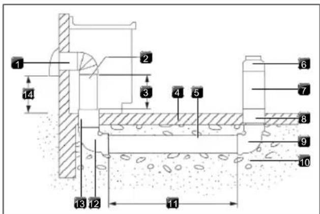
Fig. 11.19 Concrete Slab Installations - Exhaust Through Wall
[1] Wall cap
[2] 6" (15.2 cm) round metal vent
[3] 16" (40.6 cm) maximum
[4] Concrete slab
[5] 6" (15.2cm)round PVC sewer pipe
[6] 6" (15.2 cm) round metal duct
[7] 6" (15.2 cm) round PVC coupling
[8] 6" (15.2 cm) round PVC sewer pipe
[9] 6" (15.2 cm) round 90° PVC sewer pipe elbow
[10] Tightly pack gravel or sand completely around pipe
[11] 30 ft (9.1 m) max.
[12] 6" (15.2 cm) round 90° PVC sewer pipe elbow
[13] 6" (15.2 cm) round PVC coupling
[14] 12" (30.5 cm) minimum
11.11.3 Calculating Vent System Length
To calculate the length of the system you need, add the equivalent feet (meters) for each vent piece used in the system.
| Vent Piece 6" (15.2 cm) Round | ||
| 45° elbow 2.5 ft | (0.8 m) |  |
| 90° elbow 5.0 ft | (1.5 m) |  |
| 6" (15.2 cm) wall cap 0.0 ft | (0.0 m) |  |
| 3 ^1/_4 " x 10" (8.3 cm x 25.4 cm) to 6" (15.2 cm) transition | 4.5 ft(1.4 m) |  |
| 6" (15.2 cm) to 3 ^1/_4 " x 10" (8.3 cm x 25.4 cm) transition | 1 ft(0.3 m) |  |
| 3 ^1/_4 " x 10" (8.3 cm x 25.4 cm) to 6" (15.2 cm) 90° elbow transition | 5.0 ft(1.5 m) |  |
| 6" (15.2 cm) to 3 ^1/_4 " x 10" (8.3 cm x 25.4 cm) 90° elbow transition | 5.0 ft(1.5 m) | 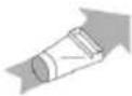 |
Vent Piece 6" (15.2 cm) Round
| 3^1/_4'' × 10'' (8.3 cm x 25.4 cm) | 5.0 ft |
| 90° elbow | (1.5 m) |
| 31/4" x 10" (8.3 cm x 25.4 cm) | 12.0 ft |
| flat elbow | (3.7 m) |
| 31/4" x 10" (8.3 cm x 25.4 cm) | 0.0 ft |
| wall cap | (0.0 m) |
Tab. 11.2 Calculating Vent System Length
11.12 Make electrical connection
WARNING

Electrical Shock Hazard
Disconnect power before servicing.
Use 10 gauge copper wire.
Electrically ground cooktop.
Failure to follow these instructions can result in death, fire, or electrical shock.
This cooktop is manufactured with a frame-connected green or bare ground wire. Connect the cooktop cable to the junction box through the UL Listed or CSA Approved conduit connector.
Electrical Connection Options
| If Your Home Has: | And You Will Be Connecting to: | Go to Section: |
| 4-wire direct | ||
 | A fused disconnect or circuit breaker box | 4-Wire Cable from Power Supply to 3-Wire Cable from Cooktop |
| 3-wire direct | ||
| A fused disconnect or circuit breaker box | 3-Wire Cable from Power Supply to 3-Wire Cable from Cooktop | |
Tab. 11.3 Electrical Connection Options
11.12.1 4-Wire Cable from Power Supply to 3-Wire Cable from Cooktop
IMPORTANT: Use the 3-wire cable from power supply where local codes do not permit connecting the frame-ground conductor to the neutral (white) junction box wire.
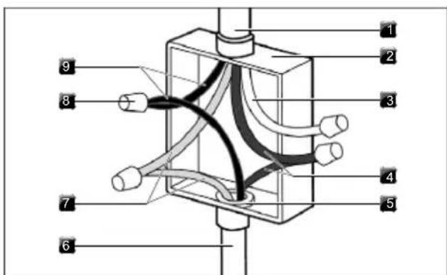
Fig. 11.20 4-Wire Cable
[1] 4-wire cable from power supply
[2] Junction box
[3] White wires
[4] Red wires
[5] UL Listed or CSA Approved conduit connector
[6] 3-wire cable from cooktop
[7] Bare or green wires
[8] UL Listed wire connector
[9] Black wires
▶ Disconnect power.
▶ Remove junction box cover, if present.
Connect the flexible cable conduit from the cooktop to the junction box using a UL Listed or CSA Approved connector for 1/2" (1.3 cm) conduit.
▶ Tighten screws on conduit connector if present.
▶ Connect the two black wires together using the UL Listed wire connectors.
▶ Connect the two red wires together using the UL Listed wire connectors.
▶ Connect the white wire using the UL Listed wire connectors.
Connect the green or bare ground wire from the cooktop cable to the green or bare ground wire (in the junction box) using the UL Listed wire connectors.
▶ Install junction box cover.
▶ Reconnect power
11.12.2 3-Wire Cable from Power Supply to 3-Wire Cable from Cooktop
IMPORTANT: Use the 3-wire cable from power supply where local codes permit connecting the frame-ground conductor to the neutral (white) junction box wire:
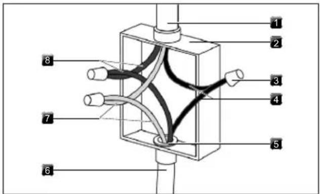
Fig. 11.21 3-Wire Cable
[1] 3-wire cable from power supply
[2] Junction box
[3] UL Listed wire connector
[4] Black wires
[5] UL Listed or CSA Approved conduit connector
[6] 3-wire cable from cooktop
[7] Green wires
[8] Red wires
▶ Disconnect power.
▶ Remove junction box cover if present.
Connect the flexible, cable conduit from the cooktop to the junction box using UL Listed or CSA Approved conduit connector.
▶ Tighten screws on conduit connector, if present.
▶ Connect the two black wires together using the UL Listed wire connectors.
▶ Connect the two red wires together using the UL Listed wire connectors.
Connect the green or bare and white cooktop cable wires to the white (neutral) wire in the junction box using the UL Listed wire connectors.
▶ Install junction box cover.
▶ Reconnect power.
11.13 Initial operation
During initial operation some basic settings (basic configuration) must be applied using the dealer and service menu.
11.13.1 Dealer and service menu
The dealer and service menu can be called up up to 2 minutes after the appliance has been connected to the power supply.
The system adopts and saves the settings made when you exit the corresponding menu item.
Below you will find explanations on how to use the menu and a description of the most important menu items.
Dealer and service menu overview
| Menu item/Description/Selection area | Factory setting |
| B Extraction system (exhaust air/recirculation system) | Exhaust air |
| C Power management 2 | |
| D Demo mode Off |
Tab. 11.4 Menu overview
Calling up the dealer and service menu
▶ Connect the appliance to the power supply.
- The standard display appears and the fan symbol pulses for 2 minutes.
▶ Long press on the fan button
- 4 input points are shown.
▶ Keep the fan button pressed and at the same time press the input points □ in the specified order.
- Menu item B is displayed.
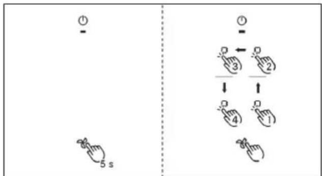
Fig. 11.22 Calling up the dealer and service menu
11.13.2 Menu item B: Extraction system configuration
There are two operating modes to choose from:
- Operating model: recirculation system
- Operating mode exhaust air system (factory setting)
▶ Select the appropriate operating mode.
▶ Confirm and save the setting by moving to the next menu item (tap the control display/indicator b).
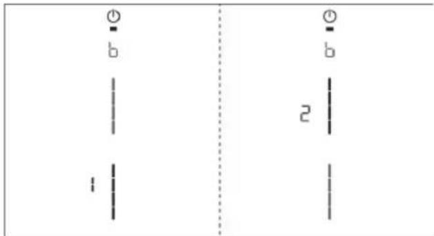
Fig. 11.23 Display Menu item B: Configuring the extraction system
11.13.3 Menu item C: Power management (for demonstration purposes only)
The total appliance power can be reduced if the required electrical power cannot be provided at the demonstration site. For single-phase operation, the input voltage needs to be converted to 220/240V using a dedicated transformer.
There are two power management settings to choose from:
| Power man-agementsettings | Connection Maximumpower con-sumption | Fuse protec-tion |
C2 2-phase 8.0 kW 2 x 40 A
C1 1-phase 1.6 kW 1 x 15 A
Tab. 11.5 Power management
Select the appropriate setting. Confirm and save the setting by moving to the next menu item (tap the control display/indicator C).
The cooking zone power restrictions automatically implemented by the appliance are determined according to the total power set.
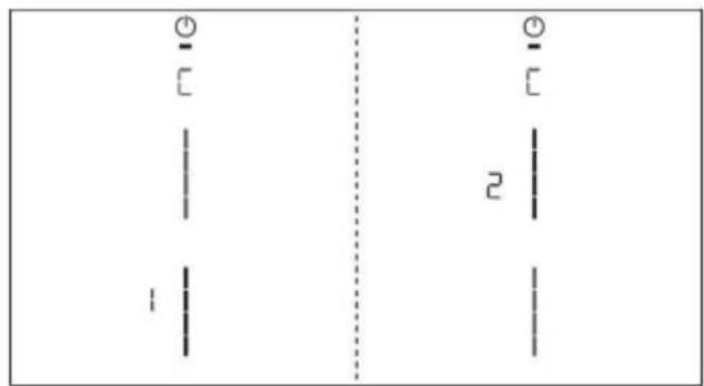
Fig. 11.24 Display menu item C: Power management
11.13.4 Menu item D: Demo mode
The appliance can be set to demo mode, which includes all operating functions, but the heating function of the cooktops is deactivated.
▶ Tap the top slider segment.
- The demo mode symbol is displayed on all cooking zones for one second.
- on is displayed.
▶ Confirm and save the setting by moving to the next menu item (tap the control display/indicator d).
Pan size recognition is deactivated in demo mode.
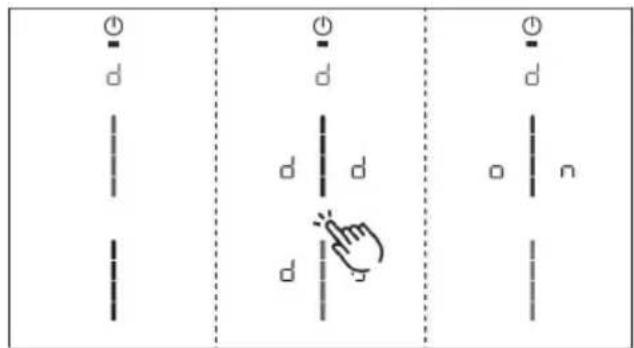
Fig. 11.25 Display Menu item D: Demo mode
Closing the dealer and service menu
When you have been through all of the basic configuration menu items:
▶ Long press on the control display.
11.13.5 Function test
▶ Carry out a thorough function test on all appliances.
In the event of error messages, see the "Troubleshooting" chapter.
11.14 Sealing the appliance

OPTIONAL based on consumer preference.
NOTE: not all stone countertops are compatible with silicone due to risk of staining the stone.
▶ Once all of the installation work is complete, seal the appliance with black, heat-resistant silicone sealant.
▶ Make sure that no silicone sealant gets under the cooktop.
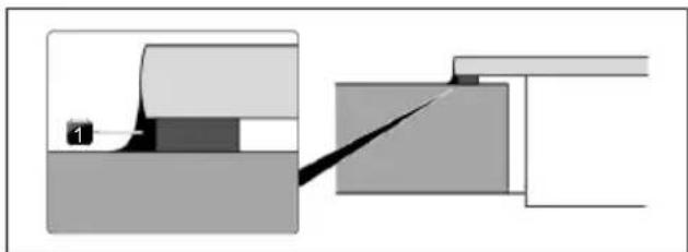
natural_image
Pure mechanical diagram showing a tool interacting with a block, no text or symbols presentFig. 11.26 Silicone sealant for surface mounting
[1] Silicone sealant
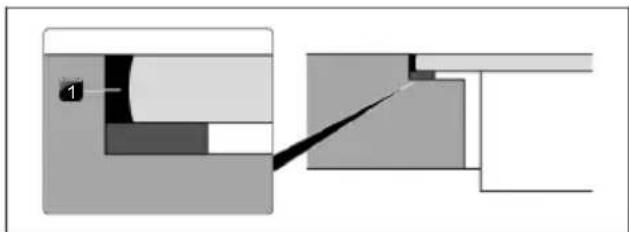
natural_image
Pure mechanical cross-section diagram without any text, numbers, or symbolsFig. 11.27 Silicone sealant for flush installation
[1] Silicone sealant
11.15 Handover to user
Once installation is complete:
Explain the main functions to the user.
Explain all aspects of operation and handling to the user.
▶ Provide the user with the accessories and operating and installation instructions, which are to be kept in place.
11.16 Spare parts / accessories
| Article Number Description |
| W11751831 Inlet nozzle |
| W11751832 Grease filter |
| W11751834 Charcoal filter |
| W11751835 Recirculation Kit |
| W11751836 Cooktop frame for width 30 inch |
| W11751837 Cooktop frame for width 36 inch |
| W11751840 36" glass ceramic with retaining frame |
| W11751846 30" glass ceramic with retaining frame |
| W11751851 B4 Induction generator horizontal |
| W11751852 Touchcontrol white |
| W11751858 Universal fan compact |
| W11751859 Extraction electronics |
| W11751860 Induction module KCID930SBL |
| W11751865 Induction module KCID936SBL |
| W11751867 Upper extraction ducting |
| W11751910 Extraction ducting clips |
| W11751911 Touch control mount |
| W11751912 Installation hardware |
Tab. 11.6 Spare parts
7.6.5 Protection anti-surchauffe.... 62
natural_image
Warning symbol: black triangle with exclamation mark (no text or numbers)Fig. 5.2 Vue avant
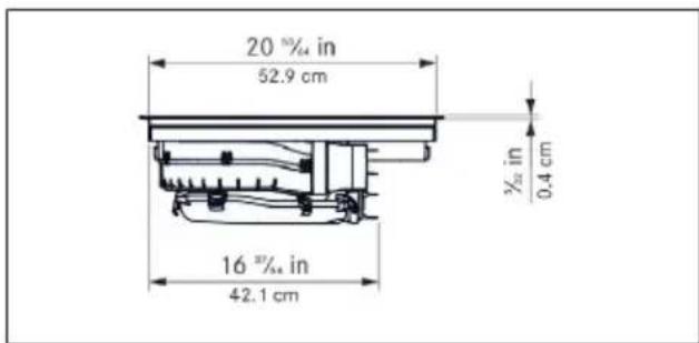
Fig. 5.5 Vue avant
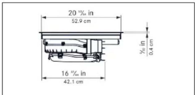
Fig. 6.1 Structure
7.6.5 Protection anti-surchauffe
Fig. 8.6 Point de menu 6 : test LED
Fin du test LED :
▶ Retirez les composants.
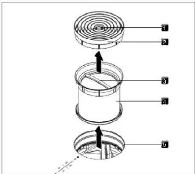
natural_image
Technical diagram of a mechanical assembly with labeled components, showing internal structure and mounting points (no text or symbols present)natural_image
Diagram of a house with crossed beams and directional arrows indicating airflow or movement (no text or symbols)natural_image
Simple line drawing of a house with airflow and a chimney, no text or symbols presentFig. 11.3 Distance requise
$$ G \geq 2 \text { in } [ \geq 5 \mathrm{cm} ] $$

B ^9/32 + ^1/64 in [0.7 + 0.05 cm]
C ^15/_32 in [1.2 cm]
National Fire Protection Association
1 Batterymarch Park
Quincy, MA 02169-7471
CSA International 8501
East Pleasant Valley Road
Cleveland, Ohio 44131-5575
natural_image
Technical line drawing of a mechanical assembly with an inset showing a close-up of a component detail (no text or symbols present)natural_image
Technical line drawing of a mechanical assembly with no visible text or symbolsnatural_image
Pure mechanical diagram showing a sliding contact and sliding block without any text or symbolsnatural_image
Pure mechanical cross-section diagram without any text, numbers, or symbolsnatural_image
Warning symbol: black exclamation mark inside a triangle (no text or numbers)Fig. 5.1 Dimensiones del aparato vista superior
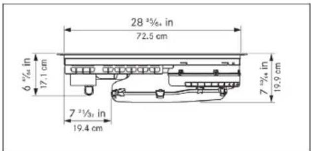
Fig. 5.2 Dimensiones del aparato vista frontal

Fig. 5.3 Dimensiones del aparato vista lateral
5.3 KCID936SBL
Fig. 5.4 Dimensiones del aparato vista superior
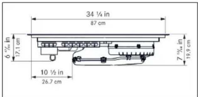
Fig. 5.5 Dimensiones del aparato vista frontal
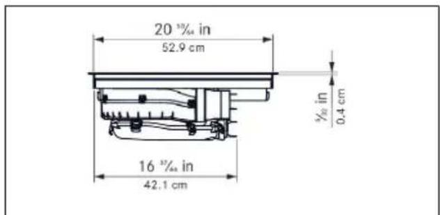
Fig. 5.6 Dimensiones del aparato vista lateral
Fig. 6.1 Estructura
[1] Tobera de entrada
[2] Filtro de grasa de acero inoxidable
[3] Placa de cocción
[4] Orificio de entrada
[5] Ventiladores
[6] Panel de mandos
[7] Zonas de cocción (4 en total)
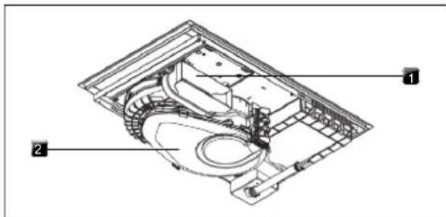
natural_image
Technical diagram of a mechanical assembly with labeled components, showing internal structure and part details (no readable text or symbols)natural_image
Diagram of a house with crossed beams and directional arrows indicating airflow or ventilation (no text or symbols)natural_image
Simple line diagram of a house with airflow and ventilation system (no text or symbols)B ^9/32 + ^1/64 in [0.7 + 0.05 cm]
C ^15/_32 in [1.2 cm]
B ^9/32 + ^1/64 in [0.7 + 0.05 cm]
C ^15/_32 in [1.2 cm]
National Fire Protection Association
1 Batterymarch Park
Quincy, MA 02169-7471
CSA International 8501
East Pleasant Valley Road
Cleveland, Ohio 44131-5575
natural_image
Technical line drawing of a mechanical assembly with an inset showing a close-up of a component detail (no text or symbols present)natural_image
Technical line drawing of a mechanical assembly with no visible text or symbolsFig. 11.20 Cable de 4 hilos
Fig. 11.21 Cable de 3 hilos
natural_image
Pure mechanical assembly diagram showing a component labeled '1' and a cutting tool interacting with a block (no text or symbols)natural_image
Pure mechanical cross-section diagram without any text, numbers, or symbolswww.kitchenaid.com/owners
1-800-422-1230

KitchenAid
www.kitchenaid.ca/owners
www.kitchenaid.ca/proprietaire
1-800-807-6777

- Operating and installation instructions KCID930SBL, KCID936SBL
- New Model / Old Model
- Contents
- Cooktop Safety
- Your safety and the safety of others are very important.
- DANGER
- WARNING
- CALIFORNIA PROPOSITION 65 WARNING
- Important safety instructions
- Installation
- General information
- Validity of the operating and installation instructions
- Presentation of information
- Technical data
- KCID930SBL
- Appliance dimensions KCID930SBL
- KCID936SBL
- Appliance dimensions KCID936SBL
- Appliance description
- Model description
- System description
- Structure
- Operating panel
- 7-segment display
- Lighting
- How the cooktop extractor works
- Exhaust air operating mode
- Recirculation air operating mode
- How the induction cooktop works
- Power levels
- Suitable cookware
- Noises
- Functions and operation
- General operating instructions
- Touch control
- Operating the system
- Switch on/off
- Timer Setting
- Activating the Timer Setting
- Setting the time
- Starting the Timer Setting
- Time lapsed
- Deactivating the Timer Setting early
- Cooktop extractor functions
- Fan power levels
- Fan power setting
- Activating the fan power setting
- Deactivating the fan power setting
- Automatic extractor function
- Activating the automatic extractor function for a cooking session:
- Deactivating the automatic extractor function:
- Switching the fan off
- Automatic after-run
- Switching off the automatic after-run early
- Filter service display
- Cooktop functions
- Pot detection
- Automatic Pot detection
- Selecting a cooking zone
- Setting cooking zone power levels
- Cooking zone power setting
- Activating the power setting for a cooking zone
- Deactivating the power setting early
- Active Zone Timer
- Activating cooking zone timers
- Starting the timer
- The set time starts to count down. The remaining time is shown on the control display.
- Showing the remaining time
- Changing active timers
- Multi-timer
- Switching the timer off early
- Pause function
- Activating the pause function
- Deactivating the pause function
- Variable heat retention function
- Activating the heat retention function
- Increasing or reducing the heat retention level
- Deactivating the heat retention function
- Bridge XL Even- Heat Zone
- Activating the Bridge XL Even- Heat Zone function
- Deactivating the Bridge XL Even- Heat Zone function
- Automatic bridge function
- Switching off the cooking zone
- Features
- Control Lock
- Permanently activating/deactivating the control lock
- Deactivating the control lock for a cooking session
- Control lock out for cleaning
- Activating the control lock out for cleaning function
- Prematurely deactivating the control lock out for cleaning function
- Heat retention function indicator
- Shut-down
- Cooktop extractor
- Overheat control
- User menu
- Calling up the user menu
- Navigating the user menu
- Closing the user menu
- Menu item 1: Volume of the acoustic signals
- Sounds
- Menu item 2: Control Lock
- Menu item 3: Show filter status and reset filter service display
- Resetting the filter service display:
- Menu item 4: Duration of the automatic after-run function
- There are three times to choose from:
- Menu item 5: Touch zone reaction speed
- Selecting the reaction speed:
- Menu item 6: LED test
- Starting the LED test:
- Ending the LED test:
- Menu item 7: Pan Size Detection
- Activate or deactivate Pan Size Detection:
- Menu item 8: Show software/hardware version
- Menu item A: Super simple mode
- Activating or deactivating super simple mode:
- Menu item 0: Reset to factory settings
- Resetting to factory settings
- Cleaning and maintenance
- Cleaning agents
- Maintenance
- Cleaning the cooktop
- Scheduled cleaning
- Heavy soiling
- Surface cleaning during operation
- Cleaning the cooktop extractor
- Cleaning the air inlet nozzle and stainless steel grease filter
- Manual cleaning
- Cleaning in the dishwasher
- Fitting the components
- Removing liquids from the appliance
- Cleaning the air guiding housing
- Opening the air guiding housing
- Closing the air guiding housing
- Troubleshooting
- Electrical Shock Hazard
- Installation
- General installation instructions
- Simultaneous operation of the cooktop extractor in the exhaust air mode with a fireplace dependent upon the air supply in the room
- Scope of delivery
- Checking the scope of delivery
- Tools and aids
- Assembly instructions
- Installation clearances
- Information on kitchen units
- Worktop cut-out
- Cut-out dimensions for flush installation (30")
- Cut-out dimensions for surface mounting (30")
- Cut-out dimensions for flush installation (36")
- Cut-out dimensions for surface mounting (36")
- Electrical Requirements
- Installing the appliance in exhaust air mode
- Preparing the appliance
- Attaching the sealing tape
- Fitting the mounting brackets
- Installation dimensions
- Installing the cooktop
- Excessive Weight Hazard
- Inserting the cooktop
- Height adjustment plates for flush installation (optional)
- Securing the cooktop
- Vent System
- Venting Requirements
- For Best Performance:
- Cold Weather Installations
- Makeup Air
- Concrete Slab Installations - Exhaust Through Wall
- Calculating Vent System Length
- Make electrical connection
- Electrical Connection Options
- 4-Wire Cable from Power Supply to 3-Wire Cable from Cooktop
- 3-Wire Cable from Power Supply to 3-Wire Cable from Cooktop
- Initial operation
- Dealer and service menu
- Calling up the dealer and service menu
- Menu item B: Extraction system configuration
- Menu item C: Power management (for demonstration purposes only)
- Menu item D: Demo mode
- Closing the dealer and service menu
- Function test
- Sealing the appliance
- Handover to user
- Once installation is complete:
- Spare parts / accessories
- Protection anti-surchauffe
- Fin du test LED :
Brand : KITCHENAID
Model : KCID936SBL
Category : Cooker