Monolith - Basket FALMEC - Free user manual and instructions
Find the device manual for free Monolith FALMEC in PDF.


User questions about Monolith FALMEC
0 question about this device. Answer the ones you know or ask your own.
Ask a new question about this device
Download the instructions for your Basket in PDF format for free! Find your manual Monolith - FALMEC and take your electronic device back in hand. On this page are published all the documents necessary for the use of your device. Monolith by FALMEC.
USER MANUAL Monolith FALMEC
natural_image
Exterior view of a black metal enclosure with ventilation grilles and ventilation slots (no text or symbols)Elements
Monolith
INSTRUCTIONS BOOKLET
LIBRETTO ISTRUZIONI ^1T
EN - Hole measurements for installation.
natural_image
Illustration of various hand tools and workwear including a screwdriver, measuring tape, gloves, a saw, a hard hat, and a pair of shoes (no text or symbols)EN - Preliminary operations: Cutting the top (1). Remove filters (2). Remove the filter drawer from the motor block (3).
natural_image
Illustration of a hand tool placed on a kitchen counter, no text or symbols present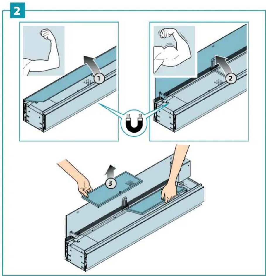
text_image
Diagram illustrating three-step mechanical assembly steps with labeled components and directional arrows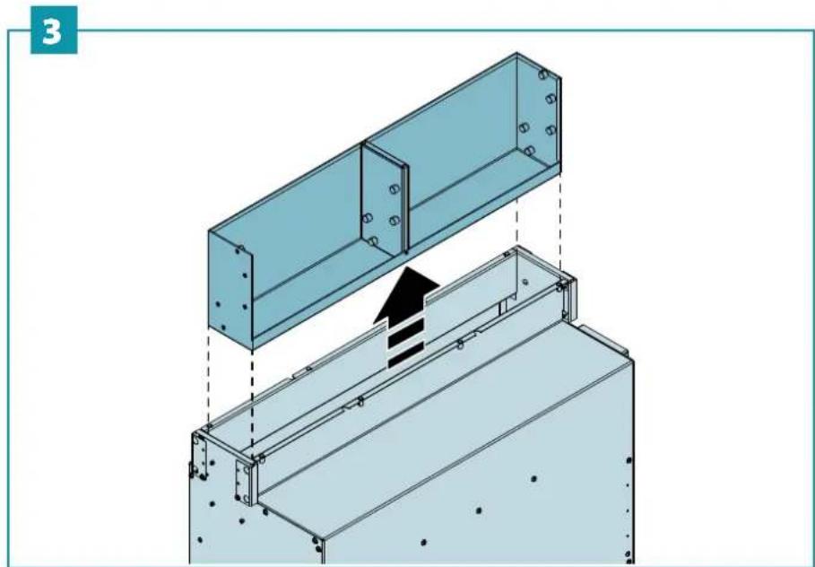
natural_image
Technical illustration of a metal frame assembly with an upward arrow indicating force or movement (no text or symbols present)4
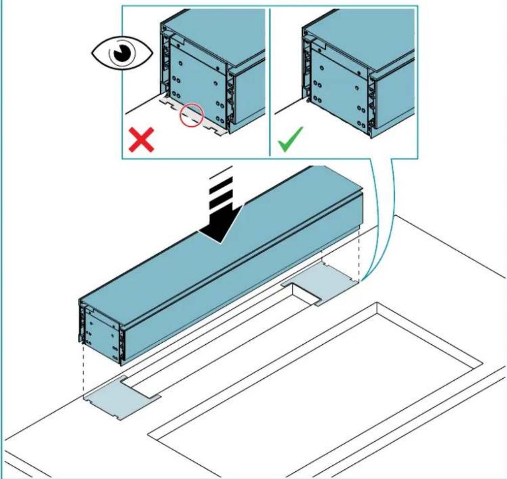
EN - Positioning mounting 'templates' (4). Place the hood on the base. Centre and align with the two templates (5).
text_image
① GLUE ② ②5
text_image
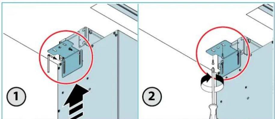
Technical diagram illustrating eye inspection and mechanical assembly process with labeled components and checkmark indicatorsEN - Position the motor under the top and fasten it to the hood (6). Mount and adjust the top fixing brackets (7).
natural_image
Pure technical diagram of a mechanical assembly with no visible text, numbers, or symbolsWALL / ISLAND
natural_image
Isometric diagram of a wall/Island structure showing two components with a black arrow indicating flow or movement (no text or symbols present)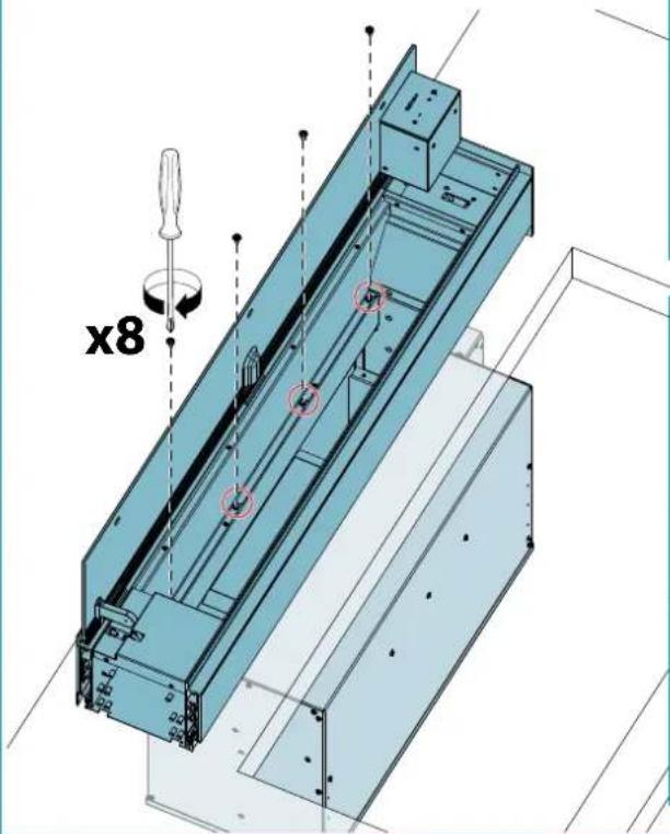
natural_image
3D technical diagram of a mechanical assembly with screwdriver and coordinate axes, no readable text or symbols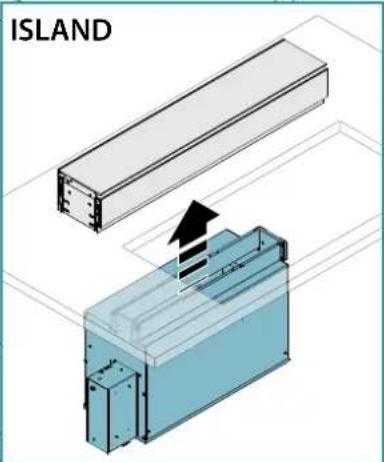
text_image
ISLAND7
text_image
Technical diagram showing two installation steps with highlighted components and directional arrows, labeled ① and ②.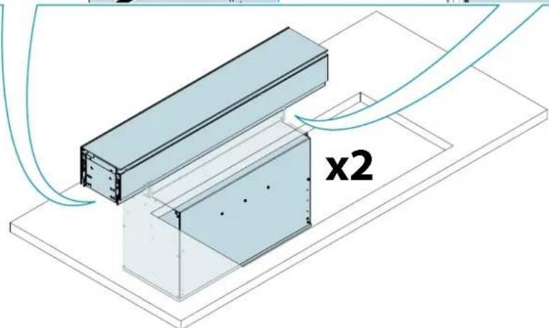
natural_image
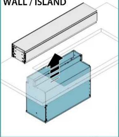
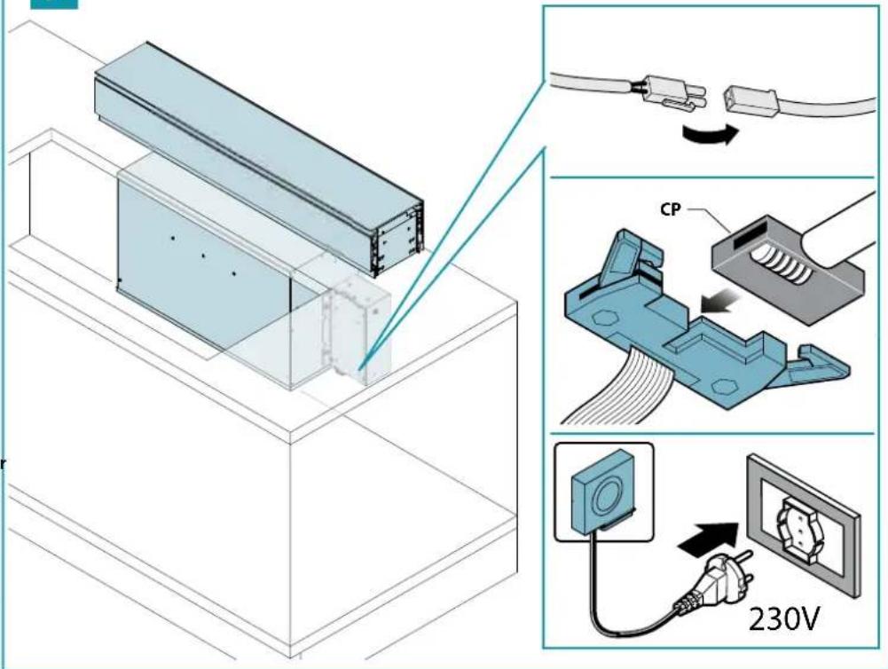
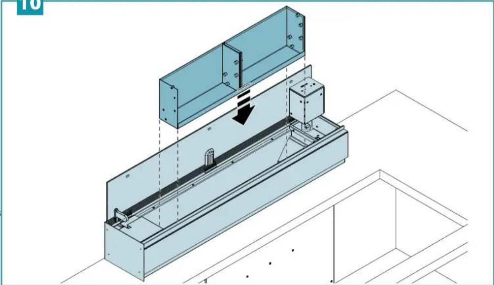
Isometric diagram of a structural assembly with two components and airflow lines, labeled 'x2' (no text or symbols beyond label)EN - Install the side infills if there are no additional shelves (8). Control, lighting and electrical connection cables (9). Repositioning of filter drawer (10).
text_image
Technical diagram illustrating three-step assembly process with labeled steps and component views9
text_image
Technical diagram illustrating cable installation process with labeled components and 230V power connection10
natural_image
Isometric technical diagram of a structural assembly with labeled components and directional arrows (no text or symbols)11
natural_image
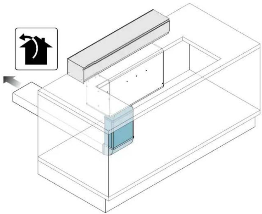
Isometric technical diagram of a mechanical assembly with a highlighted component and directional arrow (no text or symbols)EN - Installation with external exhaust hood (suction) (11).
EN - It is strongly recommended to install at least the highlighted curve also in the filter version
text_image
Technical diagram illustrating a mechanical assembly with labeled parts including a cylindrical component, screwdriver, and NRS unit, plus an inset view of a cylindrical component.
text_image
OPTIONAL ① ②
natural_image
Isometric technical diagram of a mechanical assembly with labeled components (no text or symbols present)text_image
Delivered - + *SAFETY INSTRUCTIONS AND WARNINGS

Installation operations are to be carried out by skilled and qualified installers in accordance with the instructions in this booklet and in compliance with the regulations in force.
DO NOT use the hood if the power supply cable or other components are damaged: disconnect the hood from the electrical power supply and contact the Dealer or an authorised Servicing Dealer for repairs.
Do not modify the electrical, mechanical or functional structure of the equipment.
Do not personally try to carry out repairs or replacements. Interventions carried out by incompetent and unauthorised persons can cause serious damage to the unit or physical and personal harm, not covered by the Manufacturer's warranty.
WARNINGS FOR THE INSTALLER
TECHNICAL SAFETY

Before installing the hood, check the integrity and function of each part. Should anomalies be noted, do not proceed with ation and contact the Dealer.
Do NOT install the hood if an aesthetic (or cosmetic) defect has been detected. Put it back into its original package and contact the dealer.
No claim can be made for aesthetic (or cosmetic) defects once it has been installed.
During installation, always use personal protective equipment (e.g.: Safety shoes) and adopt prudent and proper conduct.
The installation kit (screws and plugs) supplied with the hood is only to be used on masonry walls: in case of installation on walls of a different material, assess other installation options keeping in mind the type of wall surface and the weight of the hood (indicated on page 2).
Keep in mind that installations with different types of fastening systems from those supplied, or which are not compliant, can cause electrical and mechanical seal danger.
Do not install the hood outdoors and do not expose it to atmospheric elements (rain, wind, etc.).
ELECTRICAL SAFETY

The electrical system to which the hood is to be connected must be in accordance with local standards and supplied with earthed connection in compliance with safety regulations in the country of use. It must also
comply with European standards regarding radio antistatic properties.
Before installing the hood, check that the electrical mains power supply corresponds with what is reported on the identification plate located inside the hood.
The socket used to connect the installed equipment to the electrical power supply must be within reach: otherwise, install a mains switch to disconnect the hood when required.
Any changes to the electrical system must be carried out by a qualified electrician.
The maximum length of the flue fastening screws (supplied by the manufacturer) must be 13 mm. Use of non-compliant screws with these instructions can lead to danger of an electrical nature.
Do not try to solve the problem yourself in the event of equipment malfunction, but contact the Dealer or an authorised Servicing Department for repairs.

When installing the hood, disconnect the equipment by removing the plug or switch-f of the main switch.
FUMES DISCHARGE SAFETY

Do no connect the equipment to discharge pipes of fumes produced from combustion (for example boilers, fireplaces, etc.).
Before installing the hood, ensure that all standards in force regarding discharge of air out of the room have been complied with.
Deviation for Australia and New Zealand:
Range hoods and other cooking fume extractors may adversely affect the safe operation of appliances burning gas or other fuels (including those in other rooms) due to back flow of combustion gases.
These gases can potentially result in carbon monoxide poisoning. After installation of a range hood or other cooking fume extractor, the operation of flued gas appliances should be tested by a competent person to ensure that back flow of combustion gases does not occur.
(AS/NZS 60335.2.31:2013/A4:2020).
USER WARNINGS

These warnings have been drawn up for your personal safety and those of others.
You are therefore kindly asked to read the net carefully in its entirety before using the planing the equipment.
The Manufacturer declines all responsibility for any damage caused directly, or indirectly, to per-
sons, things and pets as a consequence of failing to comply with the safety warnings indicated in this booklet.
It is imperative that this instructions booklet is kept together with the equipment for any future consultation.
If the equipment is sold or transferred to another person, make sure that the booklet is also supplied so that the new user can be made aware of the hood's operation and relative warnings.
After the stainless steel hood has been installed, it will need to be cleaned to remove any residues remaining from the protection adhesive as well as any grease and oil stains which, if not removed, can cause irreversible damage to the hood surface. To properly clean the unit, the manufacturer recommends using the supplied moist wipes, which are also available sold separately.
Insist on original spare parts.
INTENDED USE
The equipment is solely intended to be used to extract fumes generated from cooking food in non-professional domestic kitchens: any other use is improper. Improper use can cause damage to persons, things, pets and exempts the Manufacturer from any liability.
The equipment can be used by children over the age of 8 and by persons with reduced physical, sensory and mental abilities, or with no experience or knowledge, as long as they do so under supervision or after having received relative instructions regarding safe use of the equipment and understanding of the dangers connected to it.
Children are not to play with the equipment. Cleaning and maintenance by the user must not be carried out by children without supervision.
USE AND CLEANING WARNINGS

Before cleaning or carrying out maintenance operations, disconnect the equipment by removing the plug or switching off the main switch.
Do not use the hood with wet hands or bare feet.
Always check that all electrical parts (lights, extractor fan) are off when the equipment is not being used.
The maximum overall weight of any objects placed or hung (if applicable) on the hood must not exceed 1.5 Kg. Always supervise the cooking process during the use of deep-fryers: Overheated oil can catch fire.
Never use the hood without the metal anti-grease filters: in this case, grease and dirt will deposit in the equipment and compromise its operation.
Accessible parts of the hood can be hot when used at the same time as the cooking appliances.
Do not carry out any cleaning operations when parts of the hood are still hot.
There can be a risk of fire if cleaning is not carried out according to the instructions and products indicated in this booklet.
Disconnect the main switch when the equipment is not used for long periods of time.

If other appliances that use gas or other fuels are being used at the same time (boiler, stove, fireplaces, etc.), make sure the room where the fumes are discharged is well-ventilated, in compliance with the local regulations.
INSTALLATION
only intended for qualified personnel

Before installing the hood, carefully read the chapter 'SAFETY INSTRUCTIONS AND WARNINGS'.
Use hobs with maximum 12 kW thermal power.
TECHNICAL FEATURES
The technical specifications are exhibited on the labels located inside the hood.
POSITIONING
The minimum distance between the highest part of the cooking equipment and the lowest part of the hood is indicated in the installation instructions.
Should the instructions for the gas cooker specify a greater distance, this must be taken into consideration.
Do not install the hood outdoors and do not expose it to outdoor environment (rain, wind, etc.).
ELECTRICAL CONNECTION
(only intended for qualified personnel)

Disconnect the equipment from electrical mains power supply before carrying out any operations on the hood.
Ensure that the wires inside the hood are not disconnected or cut: in the event of damage, contact your nearest Servicing Department.
Refer to qualified personnel for electrical connections.
Connection must be carried out in compliance with the provisions of law in force.
Before connecting the hood to the electrical mains power supply, check that:
• voltage supply corresponds with what is reported on the data plate located inside the hood;
- the electrical system is compliant and can withstand the load (see the technical specifications located inside the hood);
- the power supply plug and cable do not come into contact with temperatures exceeding 70 °C;
- the power supply system is effectively and properly connected to earth in compliance with regulations in force;
• the socket used to connect the hood is within reach.
In case of:
- devices fitted with cables without a plug: the type of plug to use is a "standardised" one. The wires must be connected as follows: yellow-green for earthing, blue for neutral and brown for the phase. The plug must be connected to an adequate safety socket.
- fixed equipment not provided with a power supply cable and plug, or any other device that ensures disconnection from the electrical mains, with an opening gap of the contacts that enables total disconnection in overvoltage category III conditions.
Said disconnection devices must be provided in the mains power supply in compliance with installation regulations.
The yellow/green earth cable must not be cut off by the switch.
The Manufacturer declines all responsibility for failure to comply with the safety regulations.
FUMES DISCHARGE
EXTERNAL EXHAUST HOOD (SUCTION)
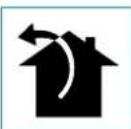
In this version the fumes and vapours are discharged outside through the exhaust pipe.
To this end, the hood outlet fitting must be connected via a pipe, to an external output.
The outlet pipe must have:
- a diameter not less than that of the hood fitting.
- a slight slope downwards (drop) in the horizontal sections to prevent condensation from flowing back into the motor.
• the minimum required number of bends. - the minimum required length to avoid vibrations and reduce the suction performance of the hood.
You are required to insulate the pipes if it passes through cold environments.
Deviation for Germany:
when the kitchen hood is used at the same time as appliances that are powered by energy other than electricity, the negative pressure in the room must not exceed 4 Pa (4 x 10⁻⁵ bar).
HOOD WITH INTERNAL RECIRCULATION (FILTERING)

In this model, air passes through the carbon and zeolite filters (optional) to be purified and is then recycled into the environment.
Ensure that the zeolite filters are assembled into the hood, if not, install them as indicated in the assembly instructions.
ASSEMBLY INSTRUCTIONS
only intended for personnel qualified

The hood can be installed in various configurations.
The generic assembly steps apply to all installations; for each case, follow the specific steps provided for the required installation.
OPERATION
WHEN TO TURN ON THE HOOD?
Switch on the hood at least one minute before starting to cook to direct fumes and vapours towards the suction surface.
After cooking, leave the hood operating until complete extraction of all vapours and odours.
WHICH SPEED IS TO BE SELECTED?
1st speed: maintains the circulation of clean air with low electricity consumption.
2nd speed: normal conditions of use.
3rd speed: presence of strong odours and vapours.
4th speed: rapid disposal of odours and vapours.
With a view to reducing environmental impact, it is suggested to always set the minimum speed suitable for the required suction level.
WHEN SHOULD THE FILTERS BE WASHED OR REPLACED?
The metal filters must be cleaned every 30 hours of operation.
For further details see the "MAINTENANCE" chap.
To access the push-button panel, the top panel must be opened: this activates the motor at speed 1.
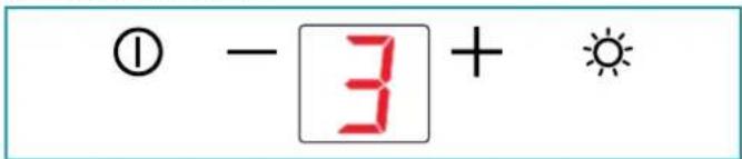
text_image
① - 3 + ☆| Opening the panel:The motor turns on at speed 1Panel closing:the motor shuts down | |
| 1 | With open panel:ON/OFF:Hood switch ON/OFF |
| + | Speed increase from 1 to...4.Speed “4”:active only for a few minutes, then speed 3. |
| - | Speed decrease from 4 to 1. |
| Turn light on and offClosing the panel does not switch off the light |

If the pushbutton panel is completely inactive, before contacting the Technical assistance service, disconnect power temporarily to the appliance (about 5"), possibly by acting on the main swi-store normal operation.
If this measure has no effect, contact the Technical assistance service.
USING THE RADIO CONTROL (OPTIONAL)

WARNINGS!:
Place the hood away from sources of electromagnetic waves (e.g.
(microwave ovens), which could interfere with the radio control with the hood electronics.
The maximum operating distance is 5 metres, that may vary according to the presence of electromagnetic interferences.
Radio control operated at 433.92MHz.
The radio control consists of two parts:
- the receiver built into the hood;
- the transmitter shown here in the figure.
| DESCRIPTION OF TRANSMITTING COMMANDS | ||
| UPMotor switch-on and speed increase from 1 to 4. Speed 4 is only active for a few minutes. | ||
| DOWNSpeed decrease and motor switch-off. | ||
| Light ON-OFF | ||
| NO FUNCTION | ||
| Command transmission active | ||
ACTIVATION PROCEDURE
Before using the radio control, follow the procedure below on the hood push-button panel:
- Press LIGHT (☀️) and ON/OFF (☐) the decimal point of the display lights up flashes
- Release the two keys and press LIGHT (☀️). Within 5 seconds: the decimal point of the display lights up steadily
- Release LIGHT (☀): now the receiver is active. This procedure is also used to deactivate the receiver.
RADIO CONTROL CODE CHANGE
If there is electromagnetic interference or more than one radio control in the vicinity, a new code can be generated using the following procedure:
1) - CREATE A NEW CODE
The procedure is to be carried out on the radio control.
- Press LIGHT Ⓞ and TIMER ⏻ simultaneously until the display starts flashing.
- Press DOWN on the radio control: saving is confirmed by three brief flashes of the display. The new code cancels and replaces the previous default code.
2) - ASSOCIATION OF RADIO CONTROL TO THE HOOD VIA PUSHBUTTON PANEL
press LIGHT (On the hood pushbutton panel for 2 seconds: the LED lights up.
Press any button on the radio control within 5 seconds or follow the Falmec induction hob pairing instructions.
RESTORING DEFAULT CODE
the procedure is to be carried out if the hood is disposed of, sold or transferred.
- Press UP and DOWN simultaneously on the radio control for more than 5 seconds: reset is confirmed by three brief flashes of the display.
- Proceed with associating the hood and the radio control, as described in point 2.
MAINTENANCE

Before cleaning or carrying out maintenance operations, disconnect the equipment by removing the plug or switching off the main switch.
Do not use detergents containing abrasive, acidic or corrosive substances or abrasive cloths.
Regular maintenance guarantees proper operation and performance over time. Special attention is to be paid to the metal anti-grease filters: frequent cleaning of the filters and their supports ensures that no flammable grease is accumulated.
CLEANING OF EXTERNAL SURFACES
You are advised to clean the external surfaces of the hood at least once every 15 days to prevent oily substances and grease from sticking to them.
Alternatively and for all the other types of surfaces, it can be cleaned using a damp cloth, slightly moistened with mild, liquid detergent.
Finish off cleaning by rinsing well and drying with soft cloths.

Do not use too much water next to the push button control panel and lighting devices in order to prevent humidity from reaching electronic parts.
The glass panels can only be cleaned with specific, non-corrosive or non-abrasive detergents using a soft cloth.
The Manufacturer declines all responsibility for failure to comply with these instructions.
CLEANING OF INTERNAL SURFACES

It is forbidden to clean electrical parts, or parts related to the motor inside the hood, with liquids or solvents.
For the internal metal parts, see the previous paragraph.
METAL ANTI-GREASE FILTERS
It is advised to frequently wash the metal filters (at least once a month) leaving them to soak in boiling water and cleaning solution for 1 hour, taking care not to bend them.
Do not use corrosive, acid or alkaline detergents.
Rinse them well and wait for them to be completely dry before reassembling them.
Washing in a dishwasher is permitted, however, it may cause the filter material to darken: to reduce this, use washes at low temperatures (60°C max.) without detergent.
To extract and insert the metal anti-grease filters see the assembly instructions.
CARBON AND ZEOLITE FILTERS (OPTIONAL)
For the service life and regeneration of filters, refer to the specific instructions supplied with their packaging.
Wait until the filter cools before reassembling it.
LIGHTING
The range hood is equipped with high efficiency, low consumption LED lighting with extremely long duration under normal use conditions.
In case of failure, contact the Dealer or an authorised Servicing Department for repairs.
DISPOSAL AFTER END OF USEFUL LIFE

The crossed-out wheeled bin symbol on the appliance means that the product is WEEE, i.e. "Waste electrical and electronic equipment", accordingly it must not be disposed of with unsorted waste (i.e. with
"mixed household waste"), but it must be disposed of separately so
that it can undergo specific operations for its re-use, or a specific treatment, to remove and safely dispose of any substances that may be harmful to the environment and remove the raw materials that can be recycled. Proper disposal of these products contributes to saving valuable resources and avoid potential negative effects on personal health and the environment, which may be caused by inappropriate disposal of waste.
You are kindly asked to contact your local authorities for further information regarding the designated waste collection points nearest to you. Penalties for improper disposal of such waste can be applied in compliance with national regulations.
INFORMATION ON DISPOSAL IN EUROPEAN UNION COUNTRIES
The EU WEEE Directive was implemented differently in each country, accordingly, if you wish to dispose of this appliance we suggest contacting your local authorities or dealer to find out what the correct method of disposal is.
INFORMATION ON DISPOSAL IN NON-EUROPEAN UNION COUNTRIES
The crossed-out wheeled bin symbol is only valid in the European Union: if you wish to dispose of this appliance in other countries, we suggest contacting your local authorities or dealer to find out what the correct method of disposal is.

WARNING!
The Manufacturer reserves the right to make changes to the equipment at any time and without prior notice. Printing, translation and reproduction, even partial, of this manual are bound by the Manufacturer's authorisation.
Technical information, graphic representations and specifications in this manual are for information purposes and cannot be divulged.
This manual is written in Italian. The Manufacturer is not responsible for any transcription or translation errors.
text_image
Digital display panel with sun icon, hourglass, and four directional icons belowFILTRES AU CHARBON-ZÉOLITE (EN OPTION)
text_image
Digital display screen with weather icons and four directional arrows below, likely indicating navigation or system control buttons.FILTRY WĘGLOWE I ZEOLITOWE (OPCJONALNE)
VEILIGHEIDSINSTRUCTIES EN WAARSCHUWINGEN

AFZUIGKAP MET AFVOER NAAR BUITEN
HVILKEN HASTIGHED SKAL MAN VÄLGE?
text_image
deaths - + *If the pushbutton panel is completely inactive, before contacting the Technical assistance service, disconnect power temporarily to the appliance (about 5"), possibly by acting on the main swi-store normal operation.
If this measure has no effect, contact the Technical assistance service.
ANVÄNDNING AV FJÄRRKONTROLL (VALFRITT)

WARNING!:
(PLANE TOP, VALINNAINEN)

VAROITUKSET!:
natural_image
Digital display with icons and symbols, no readable text or labelsBESKRIVELSE AV SENDERENS STYRINGER