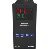
ESM-9430 - Industrial process controller Emko - Free user manual and instructions
Find the device manual for free ESM-9430 Emko in PDF.


User questions about ESM-9430 Emko
0 question about this device. Answer the ones you know or ask your own.
Ask a new question about this device
Download the instructions for your Industrial process controller in PDF format for free! Find your manual ESM-9430 - Emko and take your electronic device back in hand. On this page are published all the documents necessary for the use of your device. ESM-9430 by Emko.
USER MANUAL ESM-9430 Emko
- 4 digit process (PV) and 4 digit set (SV) display
-Universal process input (TC, RTD, mV ---, V ---, mA ---) - Dual or multi point calibration for ---Voltage & ---current inputs
- Programmable ON/OFF, P, PI, PD and PID control forms
- Auto-tune and Self-tune PID
- Manual/Automatic mode selection for control outputs
- Bumpless transfer
- Programmable heating, cooling and alarm functions for control outputs
SPECIFICATIONS PROCESS INPUT
Universal Input: TC, RTD, = Voltage/Current
Thermocouple (TC): L(DIN 43710), J, K, R, S, T, B, E and N (IEC584.1)(ITS90), C (ITS90)
Thermoresistance (RTD): PT-100 (IEC751)(ITS90)
Input: mV, V, mA
Measurement Range : Please refer to Table-1 for selection of input type and scale
Accuracy: ± 0.25% of full scale for thermocouple, thermoresistance, mV, V and mA input.
Cold Junction Compensation:Automatically ± 0.1^ / 1^
Line Compensation: Maximum 10 Ohm
Sensor break protection:Upscale
Sampling Cycle:3 samples per second Input Filter: 0.0 to 900.0 seconds
CONTROL
Control Form: ON/OFF, P, PI, PD or PID (Control form can be programmed by the user)
OUTPUT
Standard Relay Outputs : Two relays. 5A@250V~(at resistive load)
They can be programmed as Control or Alarm output
SSR Driver Output : Maximum 17mA , Max. 25V---
SUPPLY VOLTAGE
100-240 V ~ 50/60 Hz (-15%; +10%), -6VA
24V 50 / 60Hz(-15% ; + 10%) -6VA
24V = = (-15% ; + 10%) , -6W
Must be determined in order
DISPLAY
Process Display :
ESM-4430 : 10.1 mm Red 4 Digits LED Display
ESM-4930 : 13.2 mm Red 4 Digits LED Display
ESM-7730 : 13.2 mm Red 4 Digits LED Display
ESM-9930 : 19 mm Red 4 Digits LED Display
ESM-9430 : 10.1 mm Red 4 Digits LED Display
Set Value Display :
ESM-4430:8mm Green 4 Digits LED Display
ESM-4930:8mm Green 4 Digits LED Display
ESM-7730:9.1mm Green 4 Digits LED Display
ESM-9930 :10.8 mm Green 4 Digits LED Display
ESM-9430:8mm Green 4 Digits LED Display
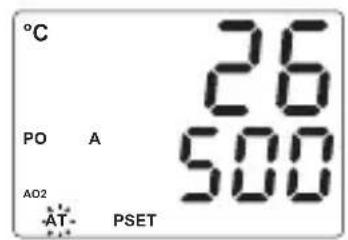
LEDS:AT(Auto Tune),M(Manual Mode),A(Automatic Mode),
PSET / ASET1 / ASET2 (Control or Alarm Set) Leds, PO, AO1, AO2
(Control or Alarm Status) ^ C / ^ F / V Leds
ENVIRONMENTAL RATINGS and PHYSICAL SPECIFICATIONS
Operating Temperature: 0 50^
Humidity: 0-90%RH (none condensing)
Protection Class : IP65 at front, IP20 at rear
Mounting: Type-1 Enclosure Mounting
Installation: Fixed installation Category II
Over Voltage Category: II
Pollution Degree: II, office or workplace, none conductive pollution
Weight:
ESM-4430:170 gr.
ESM-4930:230 gr.
ESM-7730:230 gr.
ESM-9930 : 320 gr.
ESM-9430:230 gr.
Dimensions / Panel Cut-Out:
ESM-4430 : (48 x 48mm, Depth:87.5 mm) / (46 x 46mm)
ESM-4930 : (96 x 48mm, Depth:86.5 mm) / (92 x 46mm)
ESM-7730 : (72 × 72mm, Depth:87.5 mm) / (69 × 69mm)
ESM-9930 : (96 x 96mm, Depth:87.5 mm) / (92 x 92mm)
ESM-9430 : (48 x 96mm, Depth:86.5 mm) / (46 x 92mm)
Minimum Distance Between Panel Cut-Out Centers:
ESM-4430 : X=65mm, Y=65mm
ESM-4930 : X=129mm, Y=65mm
ESM-7730:X=97mm,Y=97mm
ESM-9930 : X=129mm, Y=129mm
ESM-9430:X=65mm,Y=129mm


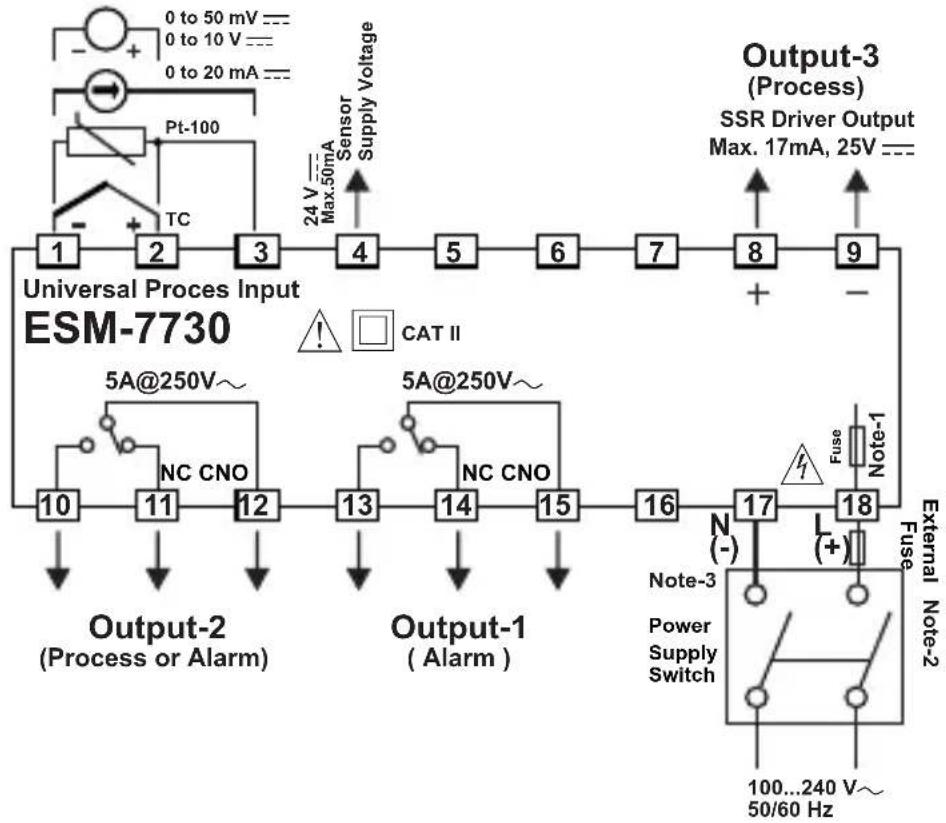
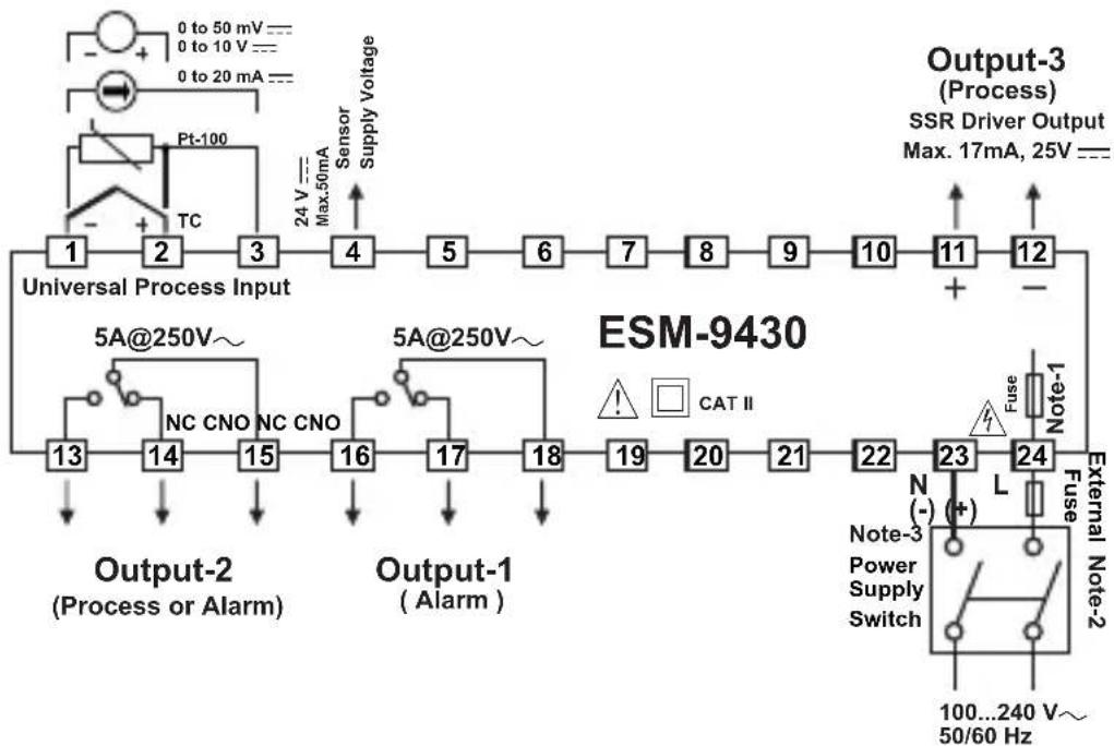
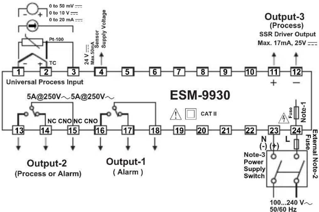
Note-1 :There is an internal fusible flameproof resistor.
Note-2 : External fuse is recommended.
- T for power supply 240 V~ or 24V~
1A---T for power supply 24V ---
Note-3: "L" is (+), "N" is (-) for 24V --- supply voltage
DIMENSIONS
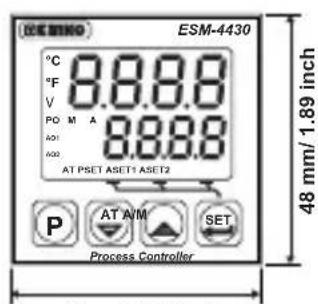
48mm/1.89 inch
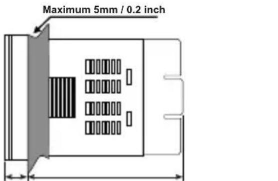
76mm/2.99 inch11.5±1 mm/0.45 inch
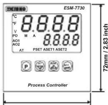
72mm/2.83 inch
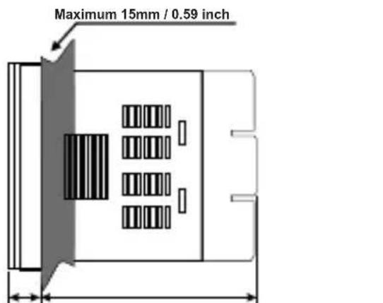
76mm/2.99 inch11.5 ± 1 mm /0.45 inch
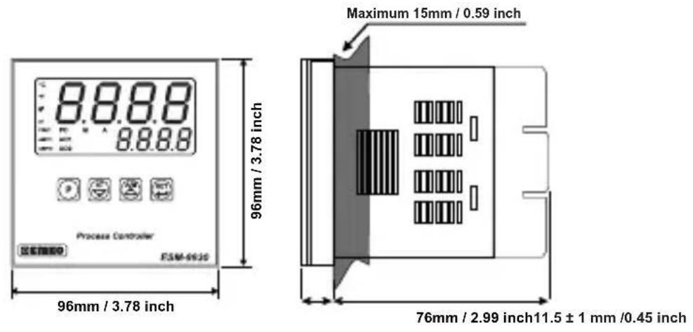
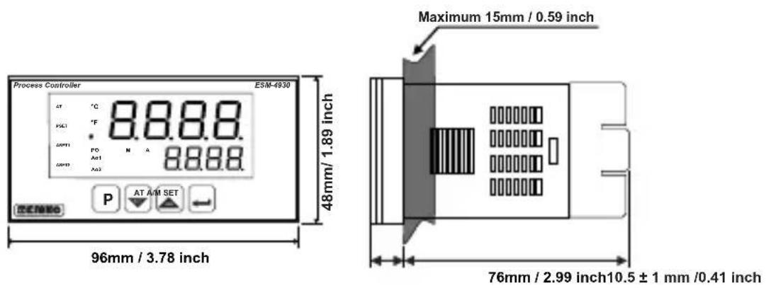
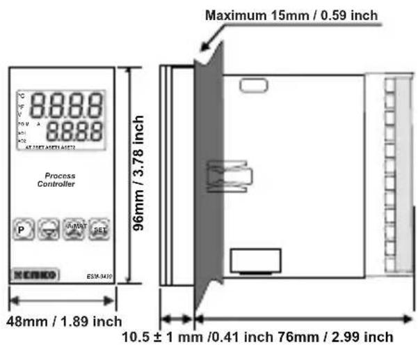
PANEL MOUNTING
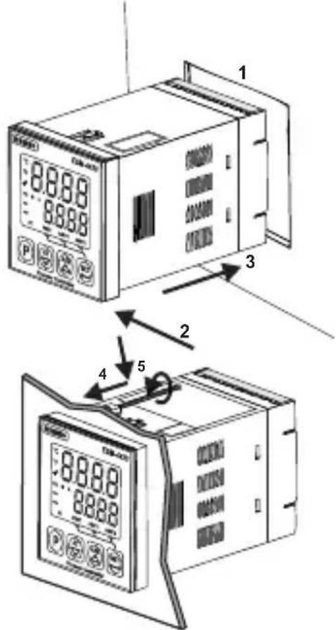
1-Before mounting the device in your panel, make sure that the panel cut-out is suitable.
2-Check front panel gasket position
3-Insert the device through the cut-out. If the mounting clamp are on the unit, put out them before inserting the unit to the panel.
4-Insert the unit in the panel cut-out from the front side.
5- Insert the mounting clamps to the holes that located top and bottom sides of device and screw up the fixing screws until the unit completely immobile within the panel
Access and change Set values
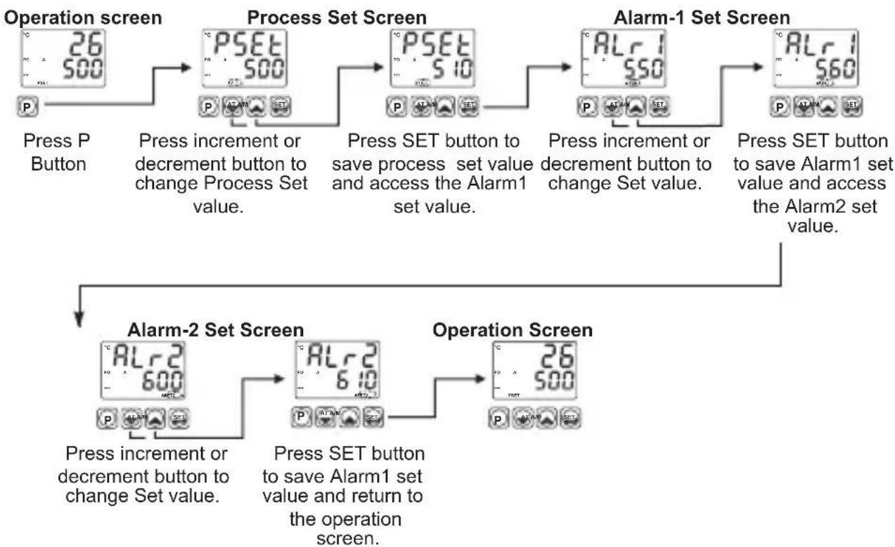
Note: User can exit from Set Value section without saving the values by pressing button. If no operation for 120 seconds, device automatically exits from Set Value section.
Easy access diagram for Program Parameters
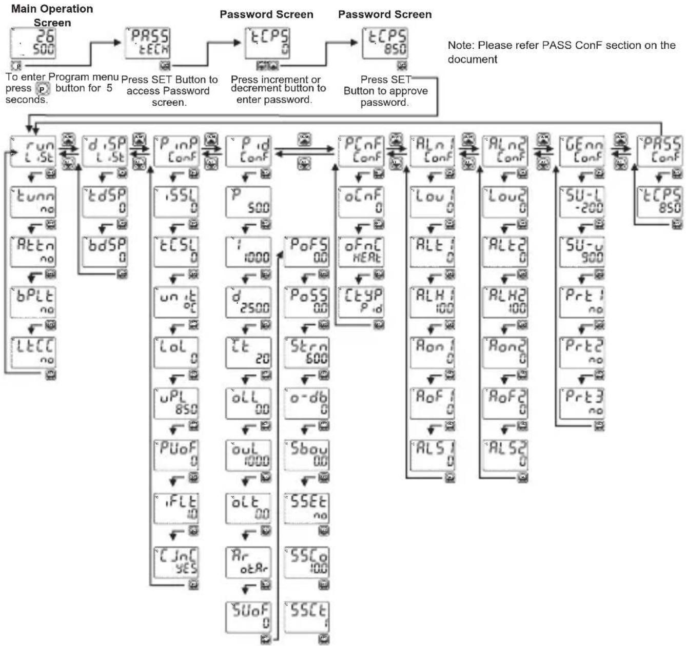
Run LiSt: Selection of PID Tune and Operation Form

TUNE SELECTION: By selecting one of the methods below, device can determine the PID parameters.

Device operates according to the defined PID parameters

Auto tune (Limit Cycle Tuning) operation

Self tune (Step Response Tuning) operation

Auto-Self Tune Tunning methods are performed according to system conditions by itself.

AUTOMATIC TUNE SELECTION

Device does not perform tunning.

Device does perform tunning.

BUMPLESS TRANSFER
When automatic mode changes to manual mode, the process output will be last saved manual mode output percentage. Process output value in manual control is not taken into consideration while passing from manual control to automatic control. New control output that is measured in automatic control is applied to process output.
When automatic mode changes to manual mode, the process output will be last automatic mode output percentage. While passing from manual control to automatic control, last process output value in manual control is accepted as first process output value in automatic control.
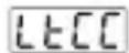
ALARM LATCH CANCELING
Alarm latch canceling is not performed.
Yes If there is an alarm output with latching and there is no alarm status, latching operation will be finished by the device. This parameter becomes no automatically.
dISP LiSt: Function Selection for Top and Bottom Display

Top Display Function
This parameter determines which value is shown in top display.
Process value (PV) is shown in top display.
Difference between process set value and process value (SV-PV) is shown in top display.
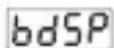
Bottom display Function
This parameter determines which value is shown in bottom display.
Process set value (SV) is shown in bottom display.
%Output value that is applied to process control output is shown in bottom display.
PinP ConF: Process Input Type and Relevant Parameters
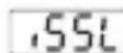
Process Input Type

TC input type selection

RTD input type selection

---Voltage / Current input type selection.
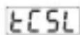
TC Input Selection
This parameter is active if TC input type is selected.
L (-100^;850^) or (-148^;1562^)
L (-100.0^;850.0^) or (-148.0^;999.9^)
J (-200^;900^) or (-328^;1652^)
J (-199.9^;900.0^) or (-199.9^;999.9^)
4 K (-200^;1300^) or (-328^;2372^)
K (-199.9°C;999.9°C) or (-199.9°F;999.9°F)
6 R (0^;1700^) or (32^;3092^)
R (0.0^;999.9^) or (32.0^;999.9^)
8 S (0^;1700^) or (32^;3092^)
S (0.0^;999.9^) or (32.0^;999.9^)
T (-200^;400^) or (-328^;752^)
T (-199.9^;400.0^) or (-199.9^;752.0^)
B (44^;1800^) or (111^;3272^)
B (44.0^;999.9^) or (111.0^;999.9^)
E (-150^;700^) or (-238^;1292^)
E (-150.0°C;700.0°C) or (-199.9°F;999.9°F)
16 N (-200^;1300^) or (-328^;2372^)
N (-199.9°C;999.9°C) or (-199.9°F;999.9°F)
C (0^;2300^) or (32^;3261^)
C (0.0^;999.9^) or (32.0^;999.9^)
rtds
RTD Input Selection
This parameter is active if RTD input is selected.
PT-100 (-200^;650^) or (-328^;1202^)
PT-100(-199.9°C;650.0°C) or (-199.9°F;999.9°F)
UASL
---voltage / Current Input Selection
This parameter is active if Voltage / Current is selected.
Display Point Position
Active if voltage / Current input is selected. = = V
No point
Between first and second digits "0.0"
Between second and third digits "0.00"
Between third and fourth digits "0.000"
U[AL
Display Value Adjustment Type
Active if oltag / Current input is selected. ---V
0 Fixed dual point display adjustment. Display adjustment low point value is fixed to -1999, display adjustment high point value is fixed to 9999.
User can do dual point display adjustment with tPoL and tPoH.
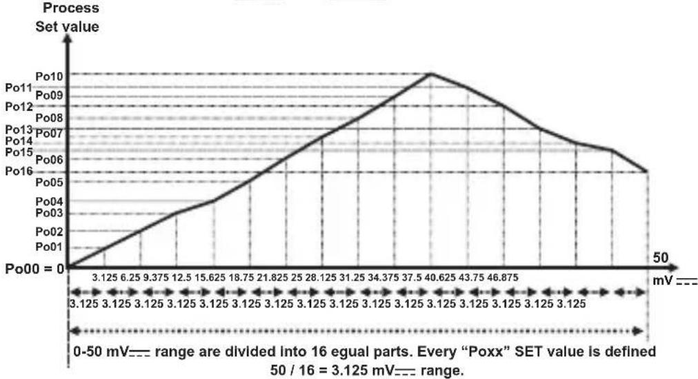
User can do defined 16 display adjustment points.
Low Point Display adjustment (-1999, 9999)Unit
Active if oltag / Current input is selected. = = V
tPoH High Point Display adjustment (-1999, 9999)Unit
Active if oltage / Current input is selected. = = V
Display adjustment points (-1999, 9999)Unit
This parameter is active if -age / Current is selected.
In multi point display adjustment operation, defined scale is divided into 16 adjustment points.
For example: wSL is 0-50 mV.
CoEF Coefficient value (1.000, 9.999)
Process value is multiplied with this value.
Active if = = Voltage / Current input is selected.
Unit selection
Unit is ^ C
Unit is ^ F
Unit is Voltage. Active if = Voltage/Current input is selected
No unit. Active if oltage / current input is selected = = = V
Lol Operating Scale Minimum Value
(Scale Low Point, Scale High Point)Unit
Used for Proportional band calculation and display blink.
UPL Operating Scale Maximum Value
(Scale Low Point, Scale High Point)Unit
Used for Proportional band calculation and display blink.
PUoF Display offset for process value (Scale -10%, Scale +10%)Unit
This parameter value is added to the process value.
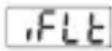
Filter Time (0.0, 900.0)Second Defines filter time for display value.
Cold Junction Compensation This parameter is active if process input is selected TC input.

Cold junction compensation is active. Cold junction compensation is not act
Scale: The difference, between high point and low point of the process input type. Example: If tCSL = 2 (low point is -200, high point is 900), then scale is 1100. If input type is Voltage/Current, then the scale is difference between tPoH and tPoL parameters.
Pid ConF: PID Configuration Parameters
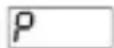
PROPORTIONAL BAND (0.0, 999.9)% If = 1000^, = 0^ and = 50.0 then, Proportional Band = ( -)^P / 100.0 Proportional Band = (1000 - 0)^50.0 / 100.0 = 500^
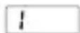
INTEGRAL TIME (0, 3600)Second Can be changed by the user. After completed the tunning correctly, integral time value changes automatically. If it is 0, integral control is deactivated.
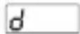
DERIVATIVE TIME (0.0, 999.9)Second Can be changed by the user. After completed the tunning correctly, integral time value changes automatically. If it is 0, derivative control is deactivated.
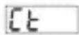
CONTROL PERIOD TIME (1, 150)Second Process output period time
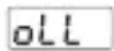
MINIMUM CONTROL OUTPUT (0.0, out)
Even as a result of the PID calculation device calculates the %output value less than this parameter, heating or cooling output is active minimum for OLL parameter.

MAXIMUM CONTROL OUTPUT (oL, 100.0)% Even as a result of the PID calculation device calculates the % output value greater than this parameter, heating or cooling output is active maximum for OUL parameter.
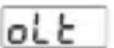
MINIMUM CONTROL OUTPUT TIME (0.0, 1)Second Heating or cooling output can not be active less than this parameter. Even if this parameter is 0, this parameter is accepted as 50 msec.
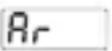
ANTI-RESET WINDUP (0, SCALE HIGH POINT)Unit
While PID operation is running if PSE - < = process value <= PSE + condition is true, integral value is calculated. If the condition is not true, integral value is not calculated and last calculated integral value is used. If Ar Parameter is selected okAr , heating proportional band is used for heating PID process instead of Ar Parameter and cooling proportional band is used for cooling PID process instead of Ar Parameter.
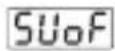
SET VALUE OFFSET
((- SCALE HIGH POINT / 2), (SCALE HIGH POINT / 2))Unit P_SEE + S_UoF is used as set value in PID calculations. This parameter is used for shifting the proportional band.

PID OUTPUT OFFSET
(FOR HEATING PID 0.0, 100.0)% (FOR COOLING PID -100.0, 0.0)%
This parameter is added to "Output %" which is calculated at the end of the PID.
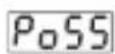
OUTPUT OFFSET RELATED TO PID SET
(FOR HEATING PID 0.0, 100.0)% (FOR COOLING PID -100.0, 0.0)%
This parameter is added to the %process output that is calculated at the end of the PID according to process set value.
Poss * PSET / (uPl - lot)
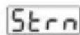
PROCESS VALUE STABILIZATION (1, SCALE HIGH POINT)Unit
It is used for controlling if process value oscillates or not when tunn Parameter is Rtun or RTe If; PSEt - Ste n < = Process Value < = PSEt ^+ Ste n condition is not true, then device start tunn operation automatically.
SCALE LOW POINT: Minimum process input value in Pt-100 and Tc inputs. -1999 for fixed dual point display adjustment used inputs, Scale low point is the lowest one from PoL drPoH for selectable dual point display adjustment used inputs Scale low point is thelowest from PocPof multi point display adjustment used inputs
SCALE HIGH POINT : Maximum process input value in Pt-100 and Tc inputs. 9999 for fixed dual point display adjustment used inputs, Scale high point is the biggest one from Pol or tPoH for selectable dual point display adjustment used inputs Scale high point is the biggest one from PoO or PoI for multi point display adjustment
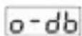
PROPORTIONAL BAND SHIFTING ((- SCALE HIGH POINT / 2), (SCALE HIGH POINT / 2))Unit
If cooling function is performed; Cooling process set value is calculated by adding set value PSET with parameter o-db Control form can be ON/OFF or PID.
If set value for heating = +SU_0F Then set value for cooling = +SU_0F + - db
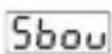
SENSOR BREAK OUTPUT VALUE (FOR HEATING PID 0.0,100.0)% (FOR COOLING PID -100.0,0.0)%
When sensor breaks, controlling of the process can continue by entering %output value to 5bou parameter. If this parameter 0.0, process control output does not perform an output when sensor breaks.
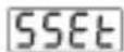
Soft Start Set value (0, 9999)Unit
If parameter is selected Soft start function becomes inactive.
When the device power on, if the Soft start set value different from no and temperature value is lower than soft start value on processes, device starts soft start operation, until temperature reaches soft start set value. On soft start device output period will be SSCt parameter value and device control output will be SSCo parameter value.
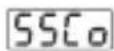
Soft Start Control Output (10.0, 90.0)%

Soft Start Control Period (1, 100)Second
PCnF ConF: Process Output Configuration Parameters
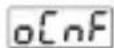
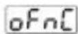
Output Configuration
Determines if Process Output (SSR Driver Output) and Alarm-2 Output operates together or not.

Process Output (SSR Driver Output) and Alarm-2 Output operates separately.

Process Output (SSR Driver Output) and Alarm-2 Output operates together. Alarm functions of Alarm-2 Output can not be used
Process Output Function

Heating

Cooling
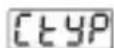
Process Output Control Type

ON/OFF control algorithm

PID control algorithm
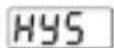
Hysteresis of Process Output (Scale 0% , Scale 50% )Unit
Active if ON/OFF control is selected.
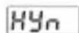
Operation form of hysteresis
Active if ON/OFF control is selected.

SV + HYS/2 and SV - HYS/2

SV and SV+HYS or SV and SV-HYS
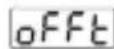
OFF Time (0.0, 100.0)Second
In ON/OFF operation, this time must be passed for the output to be energised again. (Active if ON/OFF control is selected)
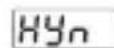
Operation form of hysteresis
Active if ON/OFF control is selected.

SV + HYS/2 and SV - HYS/2

SV and SV+HYS or SV and SV-HYS
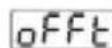
OFF Time (0.0, 100.0)Second
In ON/OFF operation, this time must be passed for the output to be energised again. (Active if ON/OFF control is selected)
Aln1 ConF: Alarm Output-1 Configuration Parameters
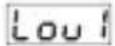
Logic Output-1
Determines logic output function for Alarm-1 Output

Alarm output
Manual / Automatic selection output

Sensor break alarm output

Output is active when the process value is out of the band which is defined with minimum value of operating scale and maximum value of operating scale uPl
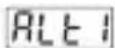
Alarm-1 Type
Determines alarm type for Output-1. Active if logic output function of Alarm-1 Output is alarm output.

Process high alarm

Process low alarm

Deviation high alarm

Deviation low alarm

Deviation band alarm

Deviation range alarm

Alarm-1 hysteresis value (Scale 0%, Scale 50%) Unit
Active if logic output function of Alarm-1 Output is alarm output.

Alarm-1 On Delay Time (0, 9999Second
Active if logic output function of Alarm-1 Output is alarm output.
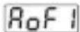
Alarm-1 Off Delay Time (0, 9998$second
When the value is greater than 9998, LeChis seen on the screen. It means alarm latching output is selected. Active if logic output function of Alarm-1 Output is alarm output.
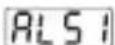
Alarm-1 Stabilization Time (0, 99)Second
Active if logic output function of Alarm-1 Output is alarm output. After the unit is power-on and Alarm Stabilisation Time is expired, if an alarm condition which is selected with Alt1 is present, then Alarm-1 output becomes active.
Aln2 ConF: Alarm-2 Output Configuration Parameters

"Aln2 Conf" Menu is accessible if parameter in "PCnF
ConF" is 0
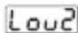
Logic Output-2
Determines logic output function for Alarm-2 Output
Alarm output
Manual / Automatic selsction output
Sensor break alarm output
Output is active when the process value is out of the band which is defined with minimum value of operating scale lot and maximum value of operating scale uPl

Alarm-2 Type
Determines alarm type for Output-2. Active if logic output function of Alarm-2 Output is alarm output.

Process high alarm

Process low alarm

Deviation high alarm

Deviation low alarm

Deviation band alarm

Deviation range alarm
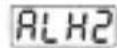
Alarm-2 hysteresis value (Scale 0% , Scale 50% )Unit
Active if logic output function of Alarm-2 Output is alarm output.
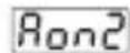
Alarm-2 On Delay Time (0, 9999second
Active if logic output function of Alarm-2 Output is alarm output.

Alarm-2 Off Delay Time (0, 9998second
When the value is greater than 9998, LeChis seen on the screen. It means alarm latching output is selected. Active if logic output function of Alarm-2 Output is alarm output.
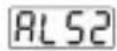
Alarm-2 Stabilization Time (0, 99second
Active if logic output function of Alarm-2 Output is alarm output. After the unit is power-on and Alarm Stabilisation Time is expired, if an alarm condition which is selected with Alt2 is present, then Alarm-2 output becomes active.
Gen ConF: General Parameters
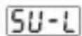
Process Set Value Low Limit (Scale Low Point, U-W)Unit

Process Set Value Up Limit (5U-L, Scale High Point)Unit
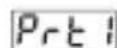
Alarm Set Values Protection

Alarm Set values can be changed

Alarm Set values can not be changed. Alarm set values parameters, - and - , are not accessible
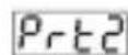
AUTO / MANUAL Selection Button Protection

Auto or Manual selection is possible with A/M button in Main Operation screen

Auto or Manual selection is not possible with A/M button in Main Operation screen
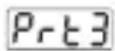
AT (AUTO TUNE) Button Protection

Limit Cycle Tuning operation can be activated or deactivated with AT (Auto Tune) Button in Operation screen

Limit Cycle Tuning operation can not be activated or deactivated with AT (Auto Tune) Button in Operation screen
PASS ConF: Password Parameters
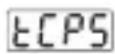
Technician Password (0, 9999)
Uses for protecting and accessing to the technician parameters.
If this parameter is 0; there is no password protection while entering to the technician parameters.
If this parameter is different from "0" and user wants to access to the technician parameters;
1- If technician does not enter CPS password correctly: It turns to operation screen without entering to technician parameters.
2- When ECP5 in top display and 0 in bottom display, if technician presses SET button without entering ECP5 password (For observing parameter)
Technician can see all menus and parameters except Technician Password menu ("Pass Conf"), but parameters can not be changed.
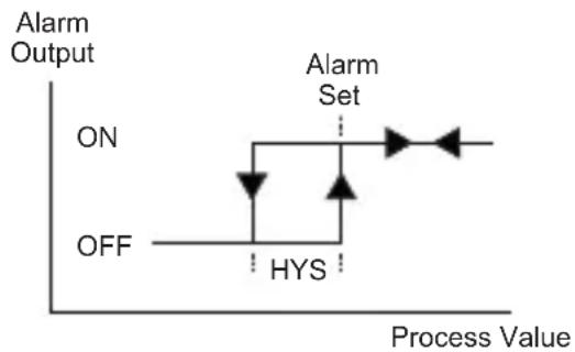
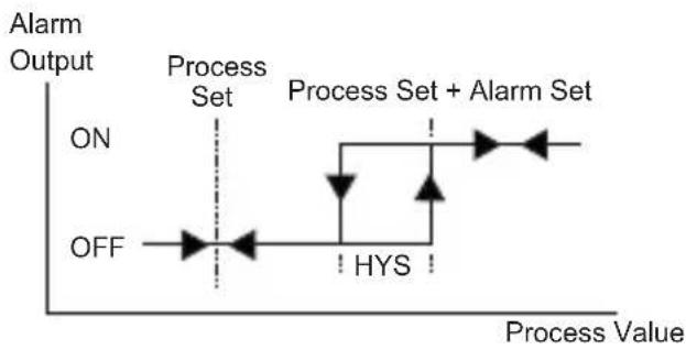
Alarm Types
Process high alarm
Process low alarm

Deviation high alarm

Deviation low alarm
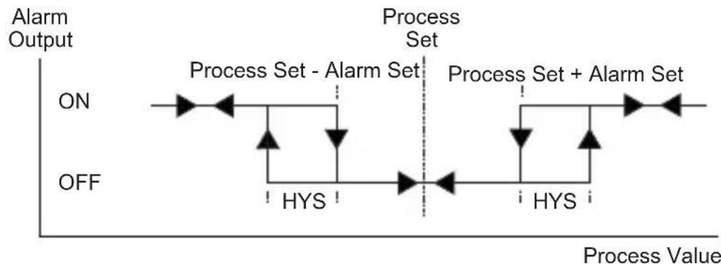
Deviation Band Alarm
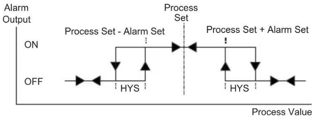
Deviation Range Alarm
Failure message in ESM-XX30 Process Controllers
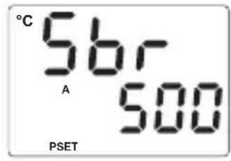
1 - Sensor failure in analogue input. Sensor connection is wrong or there is no sensor connection.

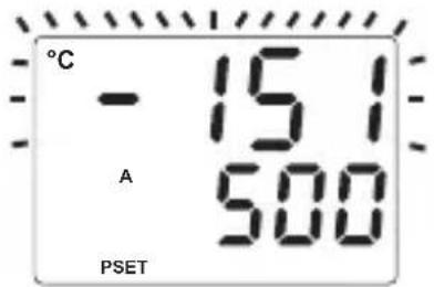
2 - If value on top display blinks : If analogue input value is less than minimum value of operating scale lol , display value on the top display starts to blink.

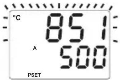
3 - If value on top display blinks : If analogue input value is greater than maximum value of operating scale display value on the top display starts to blink.

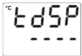
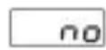
4 - If technician password is different from "0" and technician accesses to the parameters by Set button without entering the technician password and wants to change a parameter, device does not allow to do any changes in parameters. If increment or decrement button is pressed, a warning message will appear on the bottom display as shown on the left.

5 - If tuning operation can not be completed in 8 hours, AT led starts to blink.Blinking can be canceled by pressing Enter button.

Installation

Before beginning installation of this product, please read the instruction manual and warnings below carefully.
In package ,
- One piece unit
- Two pieces mounting clamp
- One piece instruction manual
A visual inspection of this product for possible damage occurred during shipment is recommended before installation. It is your responsibility to ensure that qualified mechanical and electrical technicians install this product.
If there is danger of serious accident resulting from a failure or defect in this unit, power off the system and separate the electrical connection of the device from the system.
The unit is normally supplied without a power switch or a fuse. Use power switch and fuse as required.
Be sure to use the rated power supply voltage to protect the unit against damage and to prevent failure.
Keep the power off until all of the wiring is completed so that electric shock and trouble with the unit can be prevented.
Never attempt to disassemble, modify or repair this unit. Tampering with the unit may results in malfunction, electric shock or fire.
Do not use the unit in combustible or explosive gaseous atmospheres.
During the equipment is putted in hole on the metal panel while mechanical installation some metal burrs can cause injury on hands, you must be careful.
Montage of the product on a system must be done with it's mounting clamp. Do not do the montage of the device with inappropriate mounting clamp. Be sure that device will not fall while doing the montage.
It is your responsibility if this equipment is used in a manner not specified in this instruction manual.
Warranty
EMKO Elektronik warrants that the equipment delivered is free from defects in material and workmanship. This warranty is provided for a period of two years. The warranty period starts from the delivery date.
This warranty is in force if duty and responsibilities which are determined in warranty document and instruction manual performs by the customer completely.
MaiMaintenance
Repairs should only be performed by trained and specialized personnel. Cut power to the device before accessing internal parts.
Do not clean the case with hydrocarbon-based solvents (Petrol,
Trichlorethylene etc.). Use of these solvents can reduce the mechanical reliability of the device. Use a cloth dampened in ethy alcohol or water to clean the external plastic case.
Manufacturer Information:
Emko Elektronik Sanayi ve Ticaret A.S.
Bursa Organize Sanayi Bolgesi, (Fethiye OSB Mah.) Ali Osman
Sönmez Bulvari, 2. Sokak, No:3 16215 BURSA - TÜRKİYE
Phone : +90 224 261 1900
Fax : +90 224 261 1912
Repair and maintenance service information:
Emko Elektronik Sanayi ve Ticaret A.Ş.
Bursa Organize Sanayi Bolgesi, (Fethiye OSB Mah.)
Ali Osman Sonmez Bulvari, 2. Sokak, No:3 16215
BURSA - TÜRKİYE
Phone : +90 224 261 1900
Fax : +90 224 261 1912
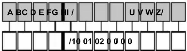
Ordering Information
ESM-4430 (48x48 DIN 1/16)
ESM-4930 (96x48 DIN 1/8)
ESM-7730 (72x72 DIN Size
ESM-9930 (96x96 DIN 1/4)
ESM-9430 (48x96 DIN 1/8)
| Supply VoltageA | |
| 1 | 100-240V ~ (-15%;+10%) 50/60Hz |
| 2 | 24V ~ (-15%;+10%) 50/60Hz or 24V --- (-15%;+10%) |
| 9 | Customer (Maximum 240V ~ (-15%;+10%))50/60Hz |
| BC | Input Type | Scale |
| 20 | Configurable(Table-1) Table-1 | |
| Serial CommunicationD | |
| 0 | None |
| E | Output-1 (Alarm) |
| 1 | Relay Output (5A@250V~ at resistive load) |
| FG | Output-2 (Process or Alarm) |
| 01 | Relay Output (5A@250V~ at resistive load) |
| HI | Output-3 (Process) |
| 02 | SSR Driver Output (Maximum 17mA, 25V ---) |
Table-1
| BC | Input Type(TC) | Scale(°C) | Scale(°F) |
| 21 | L,Fe Const DIN43710 | -100°C,850°C | -148°F,1562°F |
| 22 | L,Fe Const DIN43710 | -100.0°C,850.0°C | -148.0°F,999.9°F |
| 23 | J,Fe CuNi IEC584.1(ITS90) | -200°C,900°C | -328°F,1652°F |
| 24 | J,Fe CuNi IEC584.1(ITS90) | -199.9°C,900.0°C | -199.9°F,999.9°F |
| 25 | K,NiCr Ni IEC584.1(ITS90) | -200°C,1300°C | -328°F,2372°F |
| 26 | K,NiCr Ni IEC584.1(ITS90) | -199.9°C,999.9°C | -199.9°F,999.9°F |
| 27 | R,Pt13%Rh Pt IEC584.1(ITS90) | 0°C,1700°C | 32°F,3092°F |
| 28 | S,Pt10%Rh Pt IEC584.1(ITS90) | 0°C,1700°C | 32°F,3092°F |
| 29 | T,Cu CuNi IEC584.1(ITS90) | -200°C,400°C | -328°F,752°F |
| 30 | T,Cu CuNi IEC584.1(ITS90) | -199.9°C,400.0°C | -199.9°F,752.0°F |
| 31 | B,Pt30%Rh Pt6%Rh IEC584.1(ITS90) | 44°C,1800°C | 111°F,3272°F |
| 32 | B,Pt30%Rh Pt6%Rh IEC584.1(ITS90) | 44.0°C,999.9°C | 111.0°F,999.9°F |
| 33 | E,NiCr CuNi IEC584.1(ITS90) | -150°C,700°C | -238°F,1292°F |
| 34 | E,NiCr CuNi IEC584.1(ITS90) | -150.0°C,700.0°C | -199.9°F,999.9°F |
| 35 | N,Nicrosil Nisil IEC584.1(ITS90) | -200°C,1300°C | -328°F,2372°F |
| 36 | N,Nicrosil Nisil IEC584.1(ITS90) | -199.9°C,999.9°C | -199.9°F,999.9°F |
| 37 | C,(ITS90) | 0°C,2300°C | 32°F,3261°F |
| 38 | C,(ITS90) | 0.0°C,999.9°C | 32.0°F,999.9°F |
| BC | Input Type(RTD) | Scale(°C) | Scale(°F) |
| 39 | PT 100,IEC751(ITS90) | -200°C,650°C | -328°F,1202°F |
| 40 | PT 100,IEC751(ITS90) | -199.9°C,650.0°C | -199.9°F,999.9°F |
| BC | Input Type( ---- Voltage and Current) | Scale | |
| 41 | 0...50 mV --- | -1999,9999 | |
| 42 | 0...5 V --- | -1999,9999 | |
| 43 | 0...10 V --- | -1999,9999 | |
| 44 | 0...20 mA --- | -1999,9999 | |
| 45 | 4...20 mA --- | -1999,9999 | |

This symbol is used for safety warnings. User must pay attention to these warnings.
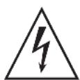
This symbol is used to determine the dangerous situations as a result of an electric shock. User must pay attention to these warnings definitely.

This symbol is used to determine the important notes about functions and usage of the device

EMKO
Thank you very much for your preference to use Emko Elektronik products, please visit our
Your Technology Partner web page to download detailed user manual.
www.emkoelektronik.com.tr




ESM-4430, ESM-7730, ESM-9930, ESM-4930, ESM-9430
(FÜR WÄRME PID (0.0, 100.0)%
(FÜR KÜHL PID (-100.0, 0.0)%
| A | BC | D | E | / | FG | HI | / | U | V | W | Z |
| 0 | 1 | / | 01 | 02 | / | 0 | 0 | 0 | 0 |
| A | Versorgungsspannung |
| 1 | 100-240V ~ (-15%;+10%) 50/60Hz |
| 2 | 24V ~ (-15%;+10%) 50/60Hz or 24V --- (-15%;+10%) |
| 9 | Kunde (Maximal 240V ~ (-15%;+10%))50/60Hz |
TENSION D'ALIMENTATION
100-240 V ~ 50/60 Hz (-15%; +10%), -6VA
24V 50 / 60Hz(-15% ; + 10%) -6VA
[ 24\mathrm{V} = (-15\%; +10\%), -6\mathrm{W} ]
TRANSFERT TRANSPARENT
Termopar (TC): L(DIN 43710), J, K, R, S, T, B, E y N
(IEC584.1)(ITS90), C (ITS90)
Termorresistencia (RTD): PT-100 (IEC751)(ITS90)---
Entrada: mV, V, mA
INGRESSO DI PROCESSO
Termocoppia (TC): L(DIN 43710), J, K, R, S, T, B, E e N (IEC584.1)(ITS90), C (ITS90)
Termoresistenza (RTD): PT-100 (IEC751)(ITS90)
Ingresso: mV, V, mA
USCITA DI CONTROLLO MINIMA (0.0,ouL)
OFFSET DI USCITA RELATIVO A IMPOSTA PID
(PER PID RISCALDAMENTO 0.0, 100.0)%
(PER IL PID RAFFREDDAMENTO -100.0, 0.0)%