
LNZ44P4B - Surveillance Camera Lorex - Free user manual and instructions
Find the device manual for free LNZ44P4B Lorex in PDF.

| Product Type | 4 MP PTZ Dome Surveillance Camera |
| Brand | Lorex |
| Model | LNZ44P4B |
| Maximum Resolution | 4 MP (2592 x 1520) |
| Sensor | 1/3-inch CMOS |
| Optical Zoom | 4x |
| Digital Zoom | 16x |
| Horizontal Field of View | 104° to 33° |
| PTZ Movement | Pan 0°-355°, Tilt 0°-90°, speed max 100°/s (pan) / 60°/s (tilt) |
| Night Vision | 0.2 lux (color), 0.02 lux (B&W) - requires ambient light |
| Day/Night Function | Auto (ICR) / Color / B&W |
| Power Supply | PoE (802.3af) or 12 V DC (adapter optional) |
| Power Consumption | 850 mA max |
| Protection Rating | IP66 (outdoor) |
| Vandal Resistance | IK10 |
| Operating Temperature | -30°C to 60°C |
| Operating Humidity | < 90% RH |
| Dimensions (camera only) | See manual section 8.1 |
| Weight (camera only) | 0.54 kg |
| Weight (with wall mount) | 1.06 kg |
| Cleaning | Soft damp cloth, water only, no chemicals |
| Reset | Button under camera module (hold 10 s) |
| NVR Compatibility | LNR/NR/LNK series (except LNR200/LNR300) |
| Connectivity | Ethernet RJ45 10/100 Base-T |
Frequently Asked Questions - LNZ44P4B Lorex
User questions about LNZ44P4B Lorex
0 question about this device. Answer the ones you know or ask your own.
Ask a new question about this device
Download the instructions for your Surveillance Camera in PDF format for free! Find your manual LNZ44P4B - Lorex and take your electronic device back in hand. On this page are published all the documents necessary for the use of your device. LNZ44P4B by Lorex.
USER MANUAL LNZ44P4B Lorex
Instruction Manual PTZ Series / P1 / LNZ44P4 4x IP PTZ DOME CAMERA
natural_image
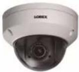
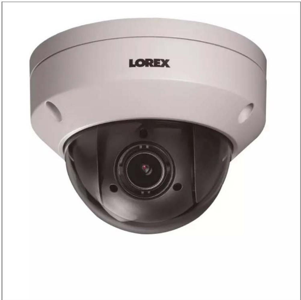
Front view of a LOREX security camera with a central lens (no visible text or symbols on the device body)Thank you for purchasing this product. Lorex is committed to providing our customers with a high quality, reliable security solution.
This manual refers to the following model:
LNZ44P4
For the latest online manual, downloads and product updates, and to learn about our complete line of accessory products, please visit our website at:
lorextechnology.com
WARNING
RISK OF ELECTRIC SHOCK DO NOT OPEN
WARNING: TO REDUCE THE RISK OF ELECTRIC SHOCK DO NOT REMOVE COVER. NO USER SERVICEABLE PARTS INSIDE.
REFER SERVICING TO QUALIFIED SERVICE PERSONNEL.
The lightning flash with arrowhead symbol, within an equilateral triangle, is intended to alert the user to the presence of uninsulated "dangerous voltage" within the product's enclosure that may be of sufficient magnitude to constitute a risk of electric shock.
The exclamation point within an equilateral triangle is intended to alert the user to the presence of important operating and maintenance (servicing) instructions in the literature accompanying the appliance.
WARNING: TO PREVENT FIRE OR SHOCK HAZARD, DO NOT EXPOSE THIS UNIT TO RAIN OR MOISTURE.
CAUTION: TO PREVENT ELECTRIC SHOCK, MATCH WIDE BLADE OF THE PLUG TO THE WIDE SLOTAND FULLY INSERT.
Table of contents
1 Safety Instructions ....1
2 Getting Started....2
3 Connecting the Camera....3
3.1 OPTION 1: Connecting Cameras to an NVR ....3
3.2 OPTION 2: Connecting Cameras to the Local Area Network (LAN) ....3
3.3 Adding the PTZ Camera to the LNR / NR Series NVRs....5
3.4 Adding the PTZ camera to the LNK Series NVRs ....6
4 Installation ....8
4.1 Installation Tips and Warnings ....8
4.2 Installation (Indoor/Outdoor)......8
4.2.1 Wall Mounting 8
4.2.2 Ceiling Mounting 13
5 Controlling the PTZ Camera with an NVR.... 14
6 Controlling the PTZ camera with LNR / NR Series NVRs 15
6.1 Controlling the PTZ Camera 15
6.2 Advanced PTZ Controls 16
6.2.1 Presets 17
6.2.2 Tours.... 17
6.2.3 Pattern.... 18
7 Controlling the PTZ camera with LNK Series NVRs 20
7.1 Controlling the PTZ camera.... 20
7.1.1 Setting PTZ Presets.... 22
8 Technical Specifications.... 23
8.1 Dimensions 24
9 Troubleshooting 25
10 Resetting the Camera 26
11 Notices....27
11.1 FCC/IC Notice....27
11.2 Modification....27
11.3 ROHS 27
1
Safety Instructions
- Read this guide carefully and keep it for future reference.
- Follow all instructions for safe use of the product and handle with care.
- Use the camera within given temperature, humidity, and voltage levels noted in the Technical Specifications.
- Camera is rated for outdoor use and is weatherproof when properly installed. Camera is not intended for submersion in water. Installation under a sheltered environment is recommended.
- Do not disassemble the camera.
- Do not point the camera directly towards the sun or a source of intense light.
- Use only the supplied regulated power supply. Use of a non-regulated, non-conforming power supply can damage this product and voids the warranty.
- Make sure to install the camera in a location that can support the camera weight.
- Make sure there are no live electrical cables in the area where you plan to mount the camera.
- Periodic cleaning may be required. Use a damp cloth only. Do not use anything other than water to clean the dome cover, as chemicals such as acetone can permanently damage the plastic.
2
Getting Started
The system comes with the following components:
 IP PTZ Dome Camera IP PTZ Dome Camera |  100ft (30.5m) Ethernet Extension Cable 100ft (30.5m) Ethernet Extension Cable | 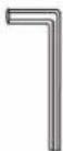 Allen Key (x2) Allen Key (x2) |
 Mounting Template Mounting Template | 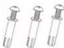 Mounting Screws (x3) & Anchors (x3)(For camera) Mounting Screws (x3) & Anchors (x3)(For camera) | 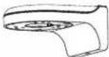 Wall Mounting Bracket Wall Mounting Bracket |
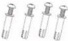 Mounting Screws ST4 (x4) & Anchors S6 (x4)(For wall mounting bracket) Mounting Screws ST4 (x4) & Anchors S6 (x4)(For wall mounting bracket) | 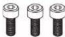 Hex Bolt M4x10 (x3)(For wall mounting bracket) Hex Bolt M4x10 (x3)(For wall mounting bracket) |  Installation Diagram Guide and Instructional Manual Installation Diagram Guide and Instructional Manual |
3
Connecting the Camera
It is recommended to connect the camera to your NVR and test the PTZ controls before permanent installation. For instructions on how to setup PTZ controls, see 5 Controlling the PTZ Camera with an NVR, page 14.
3.1 OPTION 1: Connecting Cameras to an NVR
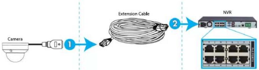
flowchart
graph LR
    A["Camera"] -->|1| B["Extension Cable"]
    B -->|2| C["NVR"]
    C --> D["Network Port"]
- Connect the PoE connector on the camera cable to the included Ethernet extension cable.
- Connect the Ethernet extension cable to one of the PoE ports on the back panel of your NVR.
| NOTE |
| You can use a single CAT5e Ethernet cable up to 300ft (91m) to connect the camera to your NCompatible with the LNR / NR / LNK Series NVRs, excluding the LNR200 and LNR300 Series.the most up-to-date list of compatible recorders, please visitlorextechnology.com/compatibility. |
3.2 OPTION 2: Connecting Cameras to the Local Area Network (LAN)
For flexibility, you may also connect the camera to the same Local Area Network (LAN) as the NVR. This is accomplished by connecting the camera to the same router (not included) as the NVR. For these installations, an external PoE switch (sold separately) or power adapter (not included) must be used to provide power to the camera. You must also add the camera on the NVR before it will show a picture on the monitor or be recorded by the NVR.
What is PoE?
PoE is a technology that allows Ethernet cables to carry electrical power to connected devices. Compatible NVRs use integrated PoE ports to provide power and PTZ commands to the camera, as well as video connection to the NVR over a single CAT5E cable. In order to use PoE with this IP camera, you must connect it directly to a compatible NVR or a Po switch on the same network as the NVR.
| NOTE |
| For the most up-to-date list of compatible recorders, please visit lorextechnology.com/compatibilityPoE switches are available for purchase on lorextechnology.com. |
Complete the following steps to connect the camera to the NVR over the LAN.
Step 1 of 2 — OPTION A: Connecting the camera to your local network using an optional PoE switch:
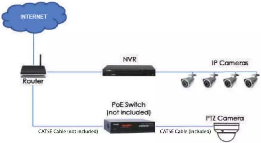
flowchart
graph TD
    A["INTERNET"] --> B["Router"]
    B --> C["NVR"]
    C --> D["IP Cameras"]
    C --> E["POE Switch (not included)"]
    E --> F["PTZ Camera"]
    F --> G["CAT5E Cable (Included)"]
    B --> H["CAT5E Cable (not included)"]
- Connect an Ethernet cable of up to 300ft (91m) rated CAT5e or higher (not included) from the LAN port on an external PoE switch (sold separately on lorextechnology.com) to your router. Connect the power cable to the PoE switch and plug into a power outlet or surge protector.

NOTE
Terminology may vary depending on the model of PoE switch you have.
- Connect the camera to the PoE switch using the included Ethernet cable (or a CAT5e Ethernet cable of up to 300ft (91m)). The PoE switch will provide power and video transmission the same way as your NVR.
Step 1 of 2 — OPTION B: Connecting the camera to your local network using a power adapter:
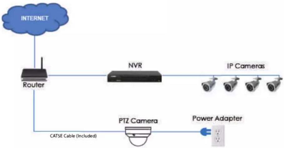
flowchart
graph TD
    A["INTERNET"] --> B["Router"]
    B --> C["NVR"]
    C --> D["IP Cameras"]
    C --> E["PTZ Camera"]
    E --> F["Power Adapter"]
    B --> G["CATSE Cable (Included)"]
- Connect the camera to a power adapter (not included).
| NOTE |
| For power requirement specification, see 8 Technical Specifications. |
- Connect the camera to a router in the same network as your NVR using the included Ethernet cable (or an Ethernet cable of up to 300ft (91m) rated CAT5e or higher).
Step 2 of 2: Add the camera to your NVR:
- For instructions on adding the PTZ camera to the LNR / NR Series NVRs, see 3.3 Adding the PTZ Camera to the LNR / NR Series NVRs, page 5
- For instructions on adding the PTZ camera to the LNK Series NVRs, see 3.4 Adding the PTZ camera to the LNK Series NVRs, page 6
| NOTE |
| For instructions on how to locate the serial and model number of your recorder, visit www.lorextechnology.com and search for "Where is the Serial and Model Number located". |
3.3 Adding the PTZ Camera to the LNR / NR Series NVRs
To add the PTZ camera to the LNR / NR Series NVRs:
The following instructions are based on the LNR400 Series NVR. See your NVR's instruction manual for instructions on controlling the PTZ camera with your system.
| NOTE |
| Not compatible with LNR200 / LNR300 Series NVRs. For the latest list of compatible recorders, forextechnology.com/compatibility. You must have at least one empty channel before attempting to add the camera to the NVR. |
- Right-click during live view and select Device Search.
- Log in using the admin account (default user name: admin; default password: 000000).
- Click Device Search. The system searches the network for compatible cameras.
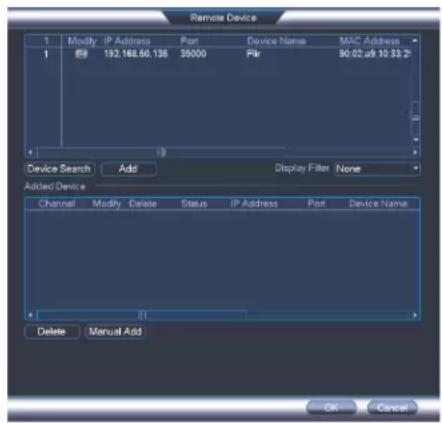
-
Check the camera(s) you would like to add.
-
Click Add. The Status indicator turns green to show the camera is successfully connected.
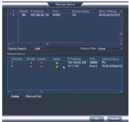
- Click OK to save changes.
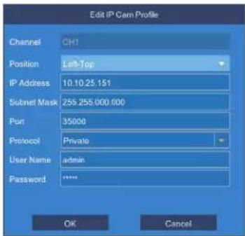
3.4 Adding the PTZ camera to the LNK Series NVRs
To add the PTZ camera to the LNK Series NVRs:
The following instructions are based on the LNK7000 Series NVR. See your NVR's instruction manual for instructions on controlling the PTZ camera with your system.
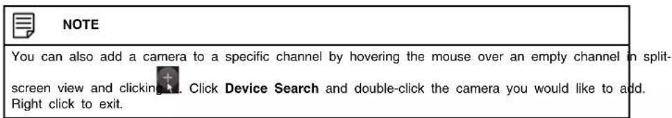
- From live view, hover over a blank channel. Click in the center of the channel to add the PTZ camera from the LAN. A Quick Add menu opens.
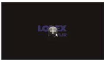
| NOTE |
| If prompted, enter the system user name (default: admin) and your password. |
- Click Search. The NVR scans the network for compatible cameras. A list of compatible cameras appear on the left-side of the screen.
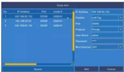
- Click the camera you would like to add. The selected camera's attributes appear on the right-side of the screen.
- Under Protocol, select ONVIF.
- Click Add.
4
Installation
4.1 Installation Tips and Warnings
- Camera is rated for outdoor use. It is recommended to install the camera in a sheltered area, such as under the eaves on a roof.
- Use the included wall mounting bracket for wall installation. Otherwise, the camera image will be sideways. You can also refer to the included installation diagram guide for wall mounting instructions.
- Camera is capable of seeing in low light conditions (0.2 Lux), but it cannot see in total darkness.

NOTE
It is recommended to install the camera where there is some ambient light (for example, street lighting or starlight, moonlight, etc.) or leave some lighting on in the area where the camera is installed.
- Mount the camera in a location that can support the camera weight.
- Mount the camera where the lens is away from direct and intense sunlight.
- Ensure you adhere to local building codes.
- Ensure that the camera wiring is not exposed or easily cut.
- Mount the camera in an area that is visible but out of reach.
- Plan your cable wiring so that it does not interfere with power lines or telephone lines.

NOTE
This camera is suitable for ceiling mounting. Wall mounting requires included wall mount.
4.2 Installation (Indoor/Outdoor)
The camera includes all necessary components for ceiling mounting and wall mounting. For full instructions on each type of mounting, see 4.2.1 Wall Mounting or 4.2.2 Ceiling Mounting.
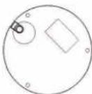
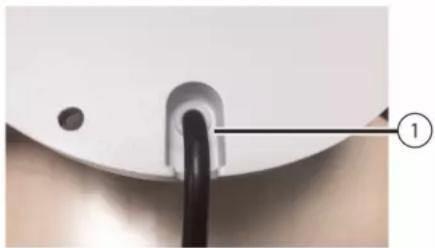
Before installing the camera, decide whether to run the cables through the wall / ceiling (drilling required) or along the wall / ceiling. If you run the cables along the wall / ceiling, you must run the cable through the cable notch on the dome camera base. This will keep the dome camera base flush to the ceiling when mounted.
natural_image
Close-up of a white circular object with a black cable inserted, labeled with number 1 (no text or symbols on the object itself)- Cable Notch
4.2.1 Wall Mounting

CAUTION
Make sure to install in a location that can support the combined weight of the wall mounting bracket and the camera.
To wall mount the camera:
- Use the Allen key (S3.0) included with the wall mounting bracket kit to loosen the hex lock on the bottom of the wall mounting bracket. Once loose, remove the back plate of the mounting bracket.
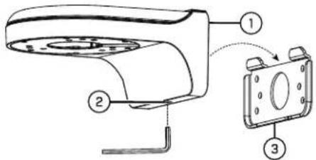
- Wall Mount
- Hex Lock
-
Back Plate
-
Use the Allen key included with the camera mounting kit to loosen the dome camera cover screws (x3). Remove the dome camera cover.
-
Insert the camera cable through the hole in the wall mounting bracket.
natural_image
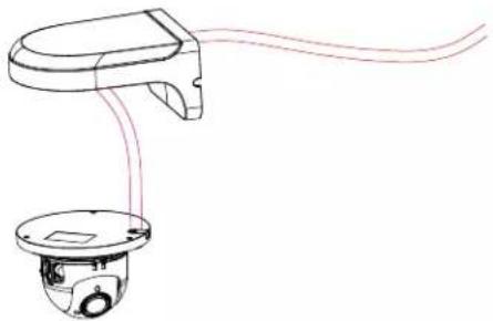
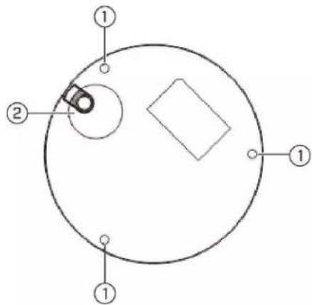
Line drawing of a handheld device with a circular base and cable routing (no text or symbols)- Ensure that the cable notch on the dome camera base is aligned with the cable notch on the wall mounting bracket. Align the 3 mounting holes on the dome camera base with the 3 corresponding mounting holes on the wall mounting bracket.
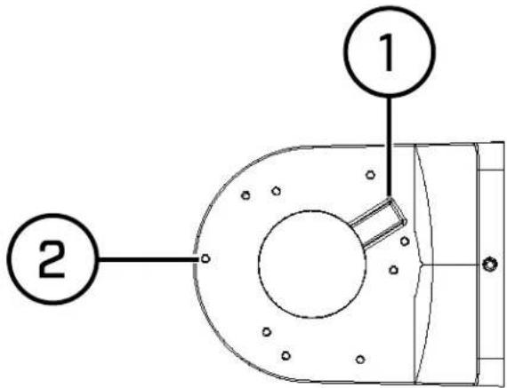
1: Cable Notch
2: Mounting Holes

NOTE
The mounting holes (3x) on the dome camera base will align with the corresponding mounting holes on the wall mount.
- Use the Hex Bolt M4x10 (x3) screws included with the wall mounting bracket kit to secure the position of the dome camera base.
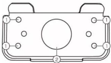
- Holding the flat side of the back plate against the mounting surface, mark holes for the mounting screws ST4 (x4) and the camera cable. Remove the back plate and drill where marked.

NOTE
You do not need to mark holes for the camera cable if you plan to run it along the wall / ceiling.
natural_image
Technical line drawing of a mechanical component with labeled parts (no text or symbols)1: Mounting screw ST4 (x4) holes, 2: Camera cable hole
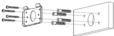
- Attach the back plate to the mounting surface using the mounting screws ST4 (x4) included with the wall mounting bracket kit.
| NOTE |
| Use the drywall anchors included with the wall mounting bracket kit if installing on a drywall surface. |
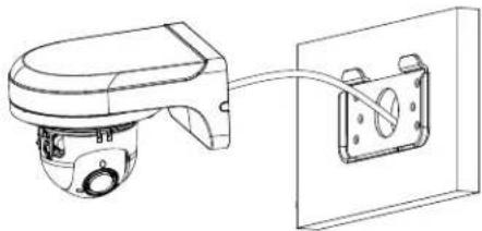
- Connect the camera cable as shown in the 3 Connecting the Camera section, then feed the cables through the cable hole in the back plate (attached to the mounting surface).
natural_image
Technical line drawing of a toilet with attached wall-mounted device (no text or symbols)| CAUTION |
| If you run the cables along the mounting surface, you must run the cable through the side notch on the wall mounting bracket. The camera cable will hang alongside the wall mounting bracket — see image below for reference: |
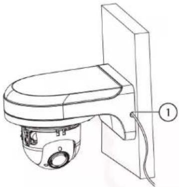 |
| 1. Side Notch |
Installation4
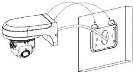
- Lower the wall mounting bracket onto the back plate. Ensure that the 2 metal flaps on the back plate lock into the 2 grooves in the wall mounting plate.
natural_image
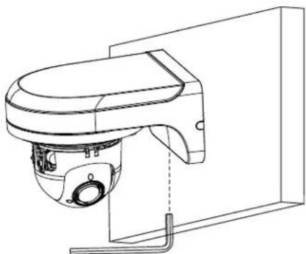
Technical line drawing of a mechanical device with attached components and wiring (no text or symbols)- Use the included Allen key (S3.0) to tighten the hex lock on the bottom of the wall mounting bracket.
natural_image
Technical line drawing of a surveillance camera mounted on a wall-mounted base (no text or symbols)- Replace the dome camera cover and tighten the dome camera cover screws using the Allen key included with the camera mounting kit.
- Remove the vinyl film from the dome cover once installation is complete.
4.2.2 Ceiling Mounting
To ceiling mount the camera:
- Use the mounting template included with the camera mounting kit to mark holes for the mounting screws (x3) and camera cable.
-
Mounting screw holes; 2. Camera cable hole (Optional)
-
Drill holes for the mounting screws, drywall anchors (optional) and camera cable (optional).
| NOTE |
| • Use the included drywall anchors if installing on a drywall surface.• If you are planning on running the cables along the mounting surface, there is no need to do hole for the camera cable. |
- Use the Allen key included with the camera mounting kit to loosen the dome camera cover screws (x3). Remove the dome camera cover.
- Connect the camera cables as shown in 3 Connecting the Camera.
- Mount the dome camera base to the mounting surface using the mounting screws (x3) and drywall anchors (x3) (optional) included with the camera mounting kit.
- Replace the dome camera cover and tighten the dome camera cover screws using the included Allen key.
- Remove the vinyl film from the dome cover once installation is complete.
5
Controlling the PTZ Camera with an NVR
The camera can accept PTZ commands directly through the Ethernet cable. There is no need to run special wiring to control the movement of the PTZ camera.
LNZ44P4 camera is compatible with LNR / NR / LNK Series NVRs, excluding the LNR200 and LNR300 Series NVRs.
- For instructions on controlling the PTZ camera with the LNR / NR Series NVRs, see 6 Controlling the PTZ camera with LNR / NR Series NVRs, page 15
- For instructions on controlling the PTZ camera with the LNK Series NVRs, see 7 Controlling the PTZ camera with LNK Series NVRs, page 20
Controlling the PTZ camera with LNR / NR Series NVRs
The following instructions are based on the LNR400 Series NVR. See your NVR's instruction manual for instructions on controlling the PTZ camera with your system. For the latest list of compatible NVRs, please visit lorextechnology.com/compatibility.
To connect the PTZ camera to the system:
- Connect the camera to your NVR as detailed in 3 Connecting the Camera, page 3.
- Right-click on the live view of the PTZ camera and click Main Menu. Enter the system user name (default: admin) and password (default: 000000) if prompted.
3. Click >SETTING>PAN/TILT/ZOOM.
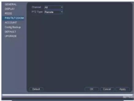
- Under Channel, select the channel your PTZ camera is connected to.
- Under PTZ Type, select Remote.
- Click OK. You can now control your PTZ camera using the system.
6.1 Controlling the PTZ Camera
- In Live View, double-click the channel that has the PTZ camera connected to open in full-screen.
- Right-click and click PTZ. Enter the system user name and password if prompted. The PTZ menu opens.
- Use the on-screen controls to control the camera.
PTZ Controls
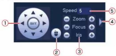
-
Direction keys: Click to pan and tilt the camera. Click SIT to stop the current action.
-
PTZ Trace: Click to activate mouse PTZ Trace mode. You can do the following:
-
Click and drag to move the camera.
- Use the scroll wheel to zoom in and out.
-
Right-click to exit and return to normal PTZ controls.
-
Zoom/Focus/Iris: Click +/- to adjust the zoom, focus, and iris. Adjusting the camera's iris settings allow you to control the amount of light that enters the camera's lens. The higher the iris value, the greater the amount of light that enters the camera's lens.
| CAUTION |
| Adjust the camera's iris settings to match the environment where the camera is installed. Too light exposure might result in a very bright camera image. |
- Advanced controls: Click to open advanced PTZ controls.
- Speed: Enter a PTZ speed between 1 (slowest) and 8 (fastest).
6.2 Advanced PTZ Controls
Advanced PTZ controls can be used to save camera positions and cycle through various positions, and automate camera actions.
To open advanced PTZ controls:
- Click the arrow in the PTZ control window to open advanced controls.
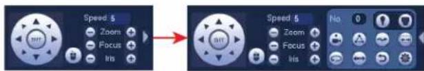
Advanced PTZ controls overview:
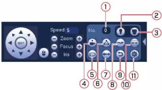
-
No.: Click to select the number of the action you want to perform.
-
Not supported.
-
Not supported.
-
Preset: Click to call the selected preset.
-
Not supported.
-
Tour: Click to run the selected tour.
-
Not supported.
-
Pattern: Click to run the selected pattern.
-
Not supported.
-
Not supported.
-
: Click to open the PAN/TILT/ZOOM menu, where you can set up Presets, Tours, and Patterns.
6.2.1 Presets
Presets will save a camera position for quick retrieval.
To add presets:
-
Click to open the PAN/TILT/ZOOM menu.
-
Click the Preset tab.
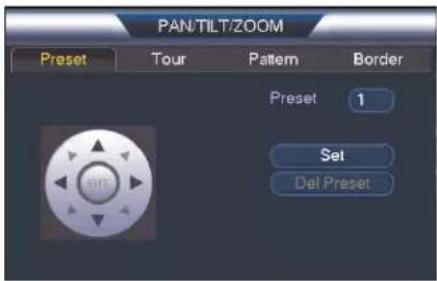
-
Under the Preset text box, enter the number of the preset you want to create.
-
Move the camera to the desired position and click Set.

NOTE
Click Del Preset to delete a preset.
- Right-click to return to the advanced PTZ controls window.
To go to a preset:
- Under No., select the number of the preset you would like to go to and click
6.2.2 Tours
Tours will cycle through a set of presets.
To create a tour:
-
Click 📋 to open the PAN/TILT/ZOOM menu.
-
Click the Tour tab.
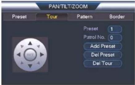
- Under Patrol No., select the tour you would like to configure.
- Under Preset, select a preset you would like to add to the tour.
- Click Add Preset.
- Repeat steps 4 and 5 to add additional presets to the tour.

NOTE
Click Del Tour to clear all presets from a tour.
- Right-click to return to the advanced PTZ controls window.
To run a tour:
• Under No., select the number of the tour you would like to go to and click

NOTE
- There is a 5 second minimum pause between presets.
- Tour panning / tilting speed is slower than manual panning / tilting speed. The reduced speed maximizes reliability.
- The camera's full panning range is 355^ . However, we recommend you do not make the camera pan more than 270^ between any two points in a tour.
6.2.3 Pattern
Patterns automatically cycle the camera between two positions.
To create a pattern:
-
Click 📋 to open the PAN/TILT/ZOOM menu.
-
Click the Pattern tab.
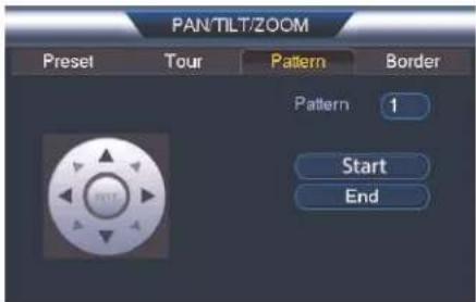
- Under Pattern, enter the pattern you would like to configure.
-
Move the camera into the desired start position and click Start.
-
Move the camera into the desired end position and click End.
- Right-click to return to the advanced PTZ controls window.
To run a pattern:
- Under No., select the number of the pattern you would like to go to and click
| NOTE |
| The camera's full panning range is 355°. However, we recommend you do not make the camera pan more than 270° between any two points in a pattern.For instructions on how to control the PTZ camera using the smartphone or tablet app, refer to your NVR's instructional manual. |
7
Controlling the PTZ camera with LNK Series NVRs
The following instructions are based on the LNK7000 Series NVR. See your NVR's instruction manual for instructions on controlling the PTZ camera with your system. For the latest list of compatible NVRs, please visit lorextechnology.com/compatibility.
To connect the PTZ camera to the system:
- Connect the camera to your NVR as detailed in 3 Connecting the Camera.
- Right-click anywhere on the live viewing mode to open the Quick Menu, then select Main Menu.
| NOTE |
| If prompted, enter the system user name (default: admin) and your password. |
-
Under Settings, click Display to open the IP Camera tab.
-
Click next to the connected PTZ camera you want to edit. The camera attributes appear.
- Under Protocol, select ONVIF.
- Click OK to save changes.
7.1 Controlling the PTZ camera
To access the PTZ controls:
- Right-click on the live viewing area for the PTZ camera to open the Quick Menu, then click PTZ. OR
- Hover the mouse near the top of the live viewing area for the PTZ camera to reveal the Mini Menu, then click.
| NOTE |
| If prompted, enter the user name (default: admin) and your secure password. |
To use the PTZ controls:

- Channel: Select the channel of the PTZ camera you want to control.
- Navigation Controls: Click the directional arrows to move the PTZ camera. Click to begin autopan (PTZ camera pans around automatically).
- Start Cruise: Cycles between preset viewing points automatically.
- Close PTZ Controls
- Speed: Set the speed of the PTZ camera's movement.
- Zoom: Click -/+ to zoom in or out.
- Focus: Click -/+ to adjust the focus.
- Iris: Click -/+ to set the iris. Adjusting the camera's iris settings allow you to control the amount of light that enters the camera's lens. The higher the iris value, the greater the amount of light that enters the camera's lens.

CAUTION
Adjust the camera's iris settings to match the environment where the camera is installed. Too much light exposure might result in a very bright camera image.
- Preset: Click to access preset settings. For details on setting presets, see 7.1.1 Setting PTZ Presets, page 22
7.1.1 Setting PTZ Presets
Access the PTZ control menu to set preset viewing points for the PTZ. This is helpful for saving frequently-monitored areas for quick viewing. Once you have saved a few preset viewing points, you can start a PTZ cruise to switch between preset points automatically
by clicking
To set PTZ presets:
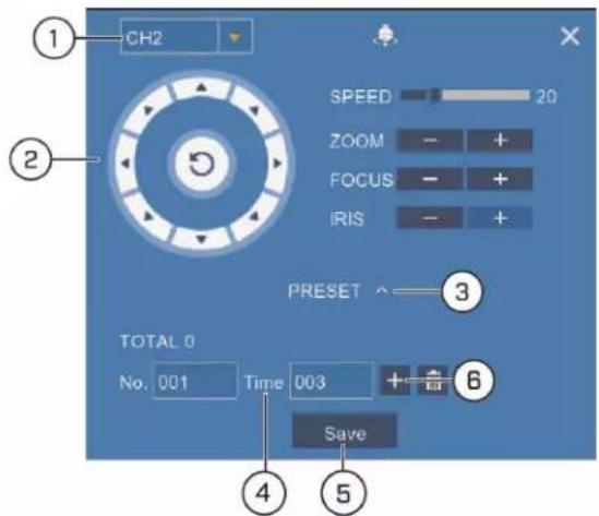
- Select the channel for the PTZ camera you want to set presets for.
- Use the directional arrows to move the PTZ camera to the desired view for the preset.
- Click the arrow next to PRESET to reveal preset controls.
- In the field next to Time, enter an amount of time in seconds. This will determine how long the PTZ camera looks at the preset area before switching to the next preset in a cruise.
- Click Save to confirm the current preset point.
- Click + to move to the next preset number in the No. field. Repeat for as many preset points as you wish to add.
Technical Specifications
| Image Sensor 1/3", CMOS 4 MP | |
| Video Format | NTSC / PAL |
| Effective Pixels 2592 (H) x 1520 (V) | |
| Resolution Up to 4MP | |
| Range 0° ~ 355° Pan; 0° ~ 90° Tilt | |
| Pan/Tilt Speed Manual Speed — Max | 100°/Sec Pan; Max 60°/Sec TiltPreset Speed — Max 100°/Sec Pan; Max 60°/Sec Tilt |
| Zoom 4x Optical Zoom & 16x Digital | Zoom |
| Scan System Progressive | |
| Synchronization Internal | |
| S / N Ratio | ≥50dB |
| Iris Auto Iris | |
| Min. Illumination 0.2 Lux in Color; 0.02 | Lux in Black and White |
| Lens / Lens Type | 2.7mm ~ 11mm, F1.6 ~ F2.8 / Zoom Module |
| Field of View (Horizontal) | 104° ~ 33° |
| Day/Night | Auto (ICR) / Color / B/W |
| Termination | RJ45 (10Base-T/100Base-TX) / DC Jack |
| Video Output | IP |
| Power Requirement | PoE (802.3af); 12V DC (Optional) |
| Power Consumption | Max. 850mA |
| Operating Temperature Range | -22°F ~ 140°F / -30°C ~ 60°C |
| Operating Humidity Range | <90%RH |
| Indoor/Outdoor | Both (IP66) ^1 |
| Vandal Resistance | IK10 |
| Weight (Camera Alone) | 1.20lbs / 0.54kg |
| Weight (Camera & Wall Mount) | 2.35lbs / 1.06kg |
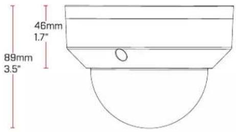
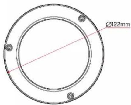
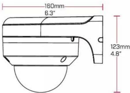
8.1 Dimensions
Camera Alone:
Camera and Wall Mount:
Troubleshooting
There is no picture at night.
- Camera is capable of seeing in extremely low light conditions (0.2 Lux), but it cannot see in total darkness. It is recommended to install the camera where there is some ambient light (e.g. street lighting, starlight, moonlight, etc.) or leave a light on in the area where the camera is installed.
No image at startup.
- The camera may take up to 1 minute to power up after being connected to the NVR. Wait 2 minutes before following steps below.
- Check to ensure your camera is properly connected (see 3 Connecting the Camera).
- Ensure the camera is connected to a router on the same network as the NVR.
- If the camera is connected to the LAN, you must search your network for cameras using the NVR. See your NVR's instruction manual for details.
- Make sure that the cable run is within the limitations specified in 3 Connecting the Camera. All Ethernet cables must be rated CAT5e or higher.
- If using the power adapter (not included), connect the power adapter to a different outlet.
- Ethernet cable may be damaged or not connected properly. Check your cable run or try a different cable.
- Reset the camera to factory default settings. See 10 Resetting the Camera for details.
No image or camera image is unclear.
- Dome cover is dirty. Clean the dome cover with a soft, slightly damp cloth. Do not use anything other than water to clean the dome cover, as chemicals such as acetone can permanently damage the plastic.
Image is distorted.
- Digital zoom is activated. Activating digital zoom may reduce the resolution of the camera image. Zoom out completely to return to the camera's optimal resolution. See 6.1 Controlling the PTZ Camera for instructions on using the zoom controls.
- Image may become unclear when camera is tilted too close to the camera base (e.g. pointed parallel to the ceiling). Tilt the camera using NVR PTZ controls.
Image is too bright.
- Ensure your camera isn't pointed directly at a source of light (e.g. sun or spot light).
- Check your NVR's brightness and contrast settings.
- Move your camera to a different location.
Image is too dark.
- Check your NVR's brightness and contrast settings.
- Move your camera to a different location.
NVR motion detection is constantly triggering.
- Turn off motion detection on the channel the PTZ camera is connected to. NVRs use video motion detection, which means they detect motion by looking for changes between frames (images) in the video. If the camera is moving, the NVR will detect this as motion.
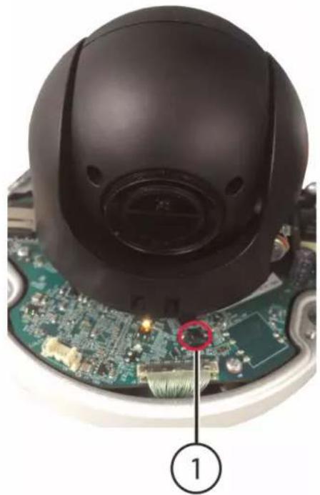
Resetting the Camera
The camera features a hard reset button that is used to reset all camera settings back to the default values. This is useful in case you want to revert camera image settings back to the default values.
To reset the camera:
- Connect the camera as detailed in 3 Connecting the Camera. Make sure the camera is powered on.
- Use the Allen key included with the camera mounting kit to loosen the dome camera cover screws (x3). Remove the dome camera cover.
- Press and hold the reset button below the camera module for at least 10 seconds to reset the camera to default settings.
natural_image
Close-up of a black spherical device with a close-up of its internal components, placed on a circuit board (no visible text or symbols)1. Reset Button

NOTE
- It may take few minutes for the camera image to reappear on the screen.
- This camera does not support micro SD card recording.
Notices
This product has been certified and found to comply with the limits regulated by FCC, EMC, and LVD. Therefore, it is designated to provide reasonable protection against interference and will not cause interference with other appliance usage. However, it is imperative that the user follows the guidelines in this manual to avoid improper usage, which may result in damage to the product, electrical shock and fire hazard injury.
11.1 FCC/IC Notice
This equipment has been tested and found to comply with the limits for a Class B digital device, pursuant to Part 15 of the FCC Rules. These limits are designed to provide reasonable protection against harmful interference in a residential installation. This equipment generates, uses, and can radiate radio frequency energy and, if not installed and used in accordance with the instruction, may cause harmful interference to radio communications.
However, there is no guarantee that interference will not occur in a particular installation. If this equipment does cause harmful interference to radio or television reception (which can be determined by turning the equipment on and off), the user is encouraged to try to correct the interference by one or more of the following measures:
- Reorient or relocate the receiving antenna.
- Increase the separation between the equipment and receiver.
- Connect the equipment into an outlet on a circuit different from that to which the receiver is connected.
- Consult the dealer or an experienced radio or television technician for assistance.
11.2 Modification
Any changes or modifications not expressly approved by the grantee of this device could void the user's authority to operate the device.
This product is fully compliant with the European Union Restriction of the Use of Certain Hazardous Substances in Electrical and Electronic Equipment ("RoHS") Directive (2002/95/EC). The RoHS directive prohibits the sale of electronic equipment containing certain hazardous substances such as lead, cadmium, mercury, and hexavalent chromium, PBB, and PBDE in the European Union.
Website
www.lorextechnology.com
Copyright
© 2017, Lorex Corporation
All rights reserved worldwide. Names and marks appearing herein are either registered trademarks or trademarks of Lorex Corporation and/or its subsidiaries. All other trademarks, trade names or company names referenced herein are used for identification only and are the property of their respective owners.
Legal disclaimer
As our product is subject to continuous improvement, Lorex Corporation & subsidiaries reserve the right to modify product design, specifications & prices without notice and without incurring any obligation.E&OE.
natural_image
Front view of a LOREX surveillance camera with lens and control buttons (no text or symbols on body)RISQUE D'ÉLECTROCUTION NE PAS OUVRIR
AVERTISSEMENT : NE PAS RETIRER LE COUVERCLE AFIN RÉDUIRE LE RISQUE DE DÉCHARGES ÉLECTRIQUES. AUCUNE PIÈCE INTERNE NE NÉCESSITE D'ENTRETIEN.
flowchart
graph LR
    A["Camera\n(may not be exactly as shown)"] --> B["Extension Cable"]
    B --> C["NVR"]
flowchart
graph TD
    A["INTERNET"] --> B["Router"]
    B --> C["NVR"]
    C --> D["IP Cameras"]
    D --> E["PTZ Camera (may not be exactly as shown)"]
    B --> F["POE Switch (not included)"]
    B --> G["CAT5E Cable (not included)"]
    F --> H["CAT5E Cable (Included)"]
natural_image
Close-up of a white circular object with a black cable inserted, labeled with number 1 (no text or symbols on the object itself)- Encoche pour câble
natural_image
Line drawing of a handheld device with a circular base and cable, no text or symbols presentnatural_image
Technical line drawing of a device casing with labeled components (no text or symbols)natural_image
Technical line drawing of a mechanical device connected to a wall-mounted bracket (no text or symbols)natural_image
Technical line drawing of a surveillance camera mounted on a wall-mounted device (no text or symbols present)natural_image
Technical line drawing of a mechanical device with no visible text or symbolsnatural_image
Close-up of a black spherical device mounted on a circuit board with a red circle highlighting a component (no text or symbols visible)© 2017, Lorex Corporation
CÁMARA PTZ IP TIPO DOMO 4x
natural_image
Front view of a LOREX security camera with a central lens (no visible text or symbols beyond branding)flowchart
graph TD
    A["INTERNET"] --> B["Router"]
    B --> C["NVR"]
    C --> D["IP Cameras"]
    D --> E["PTZ Camera (may not be exactly as shown)"]
    C --> F["POE Switch (not included)"]
    F --> G["CAT5E Cable (included)"]
    G --> H["..."]
    style A fill:#333,stroke:#fff,color:#fff
    style B fill:#fff,stroke:#000
    style C fill:#999,stroke:#000
    style D fill:#999,stroke:#000
    style E fill:#999,stroke:#000
    style F fill:#999,stroke:#000
    style G fill:#999,stroke:#000
    style H fill:#ccc,stroke:#000
natural_image
Close-up of a white circular object with a black cable inserted, labeled with number 1 (no text or symbols on the object itself)- Ranura para cables
4.2.1 Soporte de pared
natural_image
Line drawing of a handheld device with a circular base and cable, no text or symbols presentnatural_image
Technical line drawing of a mechanical component with labeled parts (no text or symbols)natural_image
Technical line drawing of a mechanical device connected to a wall-mounted panel (no text or symbols)
natural_image
Technical line drawing of a toilet with labeled component (no text or symbols present)natural_image
Technical line drawing of a surveillance camera mounted on a wall-mounted device (no text or symbols present)natural_image
Technical line drawing of a mechanical device with no visible text or symbols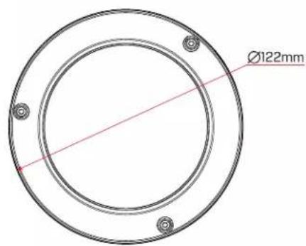
natural_image
Close-up of a black spherical device mounted on a circuit board with a magnified inset showing a small component (labeled 1), no visible text or symbols.© 2017, Lorex Corporation

- Instruction Manual PTZ Series / P1 / LNZ44P4 4x IP PTZ DOME CAMERA
- lorextechnology.com
- WARNING
- Table of contents
- 1
- Safety Instructions
- 2
- Getting Started
- 3
- Connecting the Camera
- OPTION 1: Connecting Cameras to an NVR
- OPTION 2: Connecting Cameras to the Local Area Network (LAN)
- What is PoE?
- NOTE
- Step 2 of 2: Add the camera to your NVR:
- Adding the PTZ Camera to the LNR / NR Series NVRs
- To add the PTZ camera to the LNR / NR Series NVRs:
- Adding the PTZ camera to the LNK Series NVRs
- 4
- Installation
- Installation Tips and Warnings
- Installation (Indoor/Outdoor)
- Wall Mounting
- CAUTION
- To wall mount the camera:
- Installation4
- Ceiling Mounting
- To ceiling mount the camera:
- Controlling the PTZ Camera with an NVR
- Controlling the PTZ camera with LNR / NR Series NVRs
- To connect the PTZ camera to the system:
- Click >SETTING>PAN/TILT/ZOOM.
- Controlling the PTZ Camera
- Advanced PTZ Controls
- To open advanced PTZ controls:
- Presets
- To add presets:
- To go to a preset:
- Tours
- To create a tour:
- To run a tour:
- Pattern
- To create a pattern:
- 7
- Controlling the PTZ camera with LNK Series NVRs
- Controlling the PTZ camera
- To access the PTZ controls:
- Setting PTZ Presets
- To set PTZ presets:
- Technical Specifications
- Dimensions
- Troubleshooting
- There is no picture at night.
- No image at startup.
- No image or camera image is unclear.
- Image is distorted.
- Image is too bright.
- Image is too dark.
- NVR motion detection is constantly triggering.
- Resetting the Camera
- To reset the camera:
- Reset Button
- Notices
- FCC/IC Notice
- Modification
- Website
- Copyright
- Legal disclaimer
- CÁMARA PTZ IP TIPO DOMO 4x
- Soporte de pared
Brand : Lorex
Model : LNZ44P4B
Category : Surveillance Camera