CRI915MAT - Cooker BORETTI - Free user manual and instructions
Find the device manual for free CRI915MAT BORETTI in PDF.

User questions about CRI915MAT BORETTI
0 question about this device. Answer the ones you know or ask your own.
Ask a new question about this device
Download the instructions for your Cooker in PDF format for free! Find your manual CRI915MAT - BORETTI and take your electronic device back in hand. On this page are published all the documents necessary for the use of your device. CRI915MAT by BORETTI.
USER MANUAL CRI915MAT BORETTI
natural_image
Front view of a black double boiler oven with control knobs and a horizontal indicator (no visible text or symbols)MANUAL MANUAL
CRG916 / CRI915
EN | USER MANUAL
natural_image
Exterior view of a black double boiler oven with control knobs and a visible grille (no text or symbols)MANUAL MANUAL
CRG916 / CRI915 CRG916 / CRI915
EN | USER MANUAL
www.boretti.com
Introduction
Congratulations! You are the official owner of a Boretti cooker now. In the years to come you will discover that the use of a Boretti cooker gives a new dimension to cooking.
We recommend carefully reading all the instructions in this manual, which includes detailed information about the most suitable conditions for using the cooker correctly and safely. These instructions also help you to become familiar with each component. Useful advice is given for using recipients, utensils, positions of guides and control settings.
The correct cleaning operations contained in this manual allow you to maintain the cooker's performance unchanged over time. The individual sections are set out in order to allow you to become familiar with all the functions in the cooker. The text is easy to comprehend and is accompanied with detailed images and simple pictograms. Reading this manual thoroughly will provide you with the answer to any question that may arise regarding the correct use of your new cooker.
We wish you a lot of cooking pleasure!
Boretti
Contents
* 1. General information....7
* 2. Warnings for safety and use....9
* 3. Installation....12
* 4. Description of control....27
* 5. Using the gas hob ....34
* 6. Using the induction hob 36
* 7. Using the oven ....48
* 8. Cooking suggestions....52
* 9. Care and Maintenance....58
* 10. Special maintenance....62
This user's manual is an integral part of the product purchased. The user must conserve the manual correctly so that it is always available for consultation during the use and maintenance of the product. Keep this user's manual for future reference. If the product is resold, the manual must be transferred to any subsequent owner or user of the product.
The manufacturer is not liable for any inaccuracies in this booklet resulting from printing or transcription errors. The manufacturer reserves the right to modify its products as it considers necessary or in the interests of the user, without compromising their essential safety and operating characteristics.
Classes of appliances
The cooking appliances described in this operating manual belong to the following installation classes:
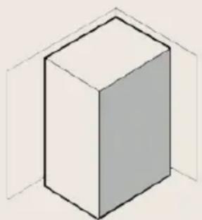
* Class 1: non-flush-mounted cooking appliance;
natural_image
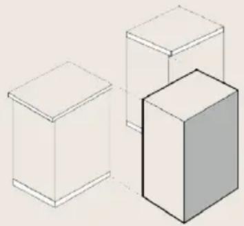
Simple 3D illustration of a rectangular prism inside a transparent cube (no text or symbols)* Class 2: subclass 1: cooking appliance flush-mounted between two units, made up of a single unit, but which can also be installed so that the side walls are accessible.
natural_image
Three 3D geometric blocks arranged in a row, one shaded gray (no text or symbols)1. General information
This product was manufactured in compliance with the following directives and regulations:
* 2014/35/EU relating to electrical equipment designed for use within certain voltage limits.
* 2014/30/EU relating to electromagnetic compatibility. In compliance with the provisions relating to electromagnetic compatibility, the electromagnetic induction hob belongs to group 2 and to class b (EN 55011).
* EU Regulation 2016/426 on "Gas Appliances".
* EC Regulation no. 1935 of 27/10/2004 and subsequent amendments on materials and articles intended to come into contact with food.
* 2011/65/EC (RoHS) on restricting the use of hazardous substances in manufacturing materials.
1.1 Technical service
Before leaving the factory, this appliance has been tested and set up by qualified, specialist personnel, so as to guarantee the best operating results. Each repair or adjustment that may subsequently be necessary must be carried out with the utmost care and attention. We therefore recommend always contacting the Dealer where the appliance was purchased or your nearest Service Centre, specifying the type of problem and the appliance model.
Environmental protection
Waste electrical products should not be disposed of with household waste. Please recycle where facilities exist. Check with your Local Authority or retailer for recycling advice. This appliance is marked according to the European directive on Waste Electrical and Electronic Equipment (WEEE). By ensuring this product is disposed of correctly, you will help prevent potential negative consequences for the environment and human health, which could otherwise be caused by inappropriate waste handling of this product. The symbol on the product indicates that this product may not be treated as household waste. Instead it shall be handed over to the applicable collection point for the recycling of electrical and
natural_image
Symbol of a trash bin crossed out by two crossed lines, with no text or labels present.electronic equipment. Disposal must be carried out in accordance with local environmental regulations for waste disposal. For more detailed information about treatment, recovery and recycling of this product, please contact your local council, your household waste disposal service or the retailer where you purchased the product.
CE Declaration of Conformity
Hereby, Boretti B.V. declares that this appliance has been manufactured to the standards of the CE Declaration of Conformity.
2. Warnings for safety and use
* This manual is an integral part of the appliance. It should be kept in good condition and close to the appliance for the whole lifecycle of the cooker. We recommend reading this manual very carefully before using the cooker. In case an additional jets kit is given as accessory to the cooker, we recommend keeping and preserving it. The installation must be carried out by qualified personnel and in compliance with current standards. This appliance is for domestic use and conforms to the eec directives currently in force. Use in a professional setting and installation within a business such as restaurant, bar, company canteen or any other use other than that specified here will immediately void the warranty. The appliance is built for carrying out the following function: cooking and heating food; any other use is to be considered improper. The manufacturer declines any responsibility should the appliance be used for purposes other than those indicated.
* At the moment of purchase, the user assumes direct responsibility for the product and must therefore make sure that, with normal use, no instability, deformation, breakage or wear occurs over time that would reduce product safety.
* This product is designed and manufactured to operate safely and does not pose any dangers to people, animals, and objects.
* Do not modify this appliance.
* Do not spray aerosols in the vicinity of this appliance while it is in operation. This appliance shall not be used as a space heater. Not for use in marine craft, caravans or mobile homes unless each burner is fitted with a flame safeguard.
* Any transit protection must be removed before use. Do not leave any pieces of the packing unattended in the home. Separate the various packing materials and deliver them to the nearest recycling centre.
* The earth connection is obligatory conforming to the modalities envisaged by the safety standards of the electrical wiring system.
* Should the gas taps be difficult to rotate, lubricate them using a specific product for high temperatures. Contact the technical service for this operation.
* Immediately after installation, test the appliance briefly by following the instructions shown below. In the event of a malfunction, disconnect the appliance from the mains and contact your nearest technical service centre. Do not attempt to repair the appliance.
* Using a gas cooking appliance produces heat and humidity in the room where it is installed. Ensure good room ventilation: keep natural ventilation grilles open or install a mechanical ventilation device (ducted extraction hood). Intensive and prolonged appliance use may require supplementary ventilation, for example, opening a window, more effective ventilation, or increasing the extraction hood power, if installed.
* Each time you finish using the cooking hob, always check that the control knobs are in "zero" position (off).
* Never put inflammable objects into the oven: should it be accidentally switched on, a fire may break out. In the event of a fire: close the main gas supply and cut off the electric current. Do not throw water on burning or frying oil. Do not store inflammable objects or aerosol cans near the appliance and do not spray near the burners when switched on. Do not wear baggy clothes or accessories that are not close to the body when the burners are switched on: serious injuries can be caused by burning fabric. Do not use or store flammable materials in the appliance storage drawer or near this appliance.
* Do not rest saucepans that do not have a perfectly smooth, even base on the cooking hob.
* Do not use recipients or steak grills that exceed the outer perimeter of the cooking hob
* The identification plate with the technical data, serial number and the mark is clearly visible on the back of the appliance; a copy is attached to the manual. A second plate, including detailed information about the model and serial number, is placed inside the equipment on the left side and is visible on opening the oven door. These plates must never be removed
* The appliance should only be used by adults. Do not allow children to approach or play with the appliance. Never store items that children may attempt to reach above the appliance. The heating up of some parts of the appliance and of the used pans may be a danger, so during functioning and during all the time necessary for the cooling down, take care to position the hot pans in a way to prevent burns or overturning. Avoid leaving the oven door open during functioning or immediately soon after the switching off. Avoid touching the heating elements inside the oven and grills as well.
* Resting or sitting on the open oven door, drawers or storage compartment can overturn the appliance, and consequently cause harm. The drawers have a dynamic capacity of 25 kg.
* If the cooker is set on a pedestal, appropriate measures must be taken to prevent it from sliding off the pedestal.
* When the appliance is decommissioned, it must be disposed of in a suitable recycling centre. Cut off the mains power cord after unplugging it from the wall outlet, and make safe any components which might be dangerous for children (doors, etc.).
* This appliance is marked according to the european Directive 2002/96/EC on waste electrical and electronic equipment (WEEE). By ensuring this product is disposed of correctly, you will help prevent potential negative consequences for the environment and human health, which could otherwise be caused by inappropriate waste handling of this product. The symbol 📄 on the product, or on the documents accompanying the product, indicates that this appliance may not be treated as household waste. Instead it shall be handed over to the applicable collection point for the recycling of electrical and electronic equipment. Disposal must be carried out in accordance with local environmental regulations for waste disposal. For more detailed information about treatment, recovery and recycling of this product, please contact your local city office, your household waste disposal service or the shop where you purchased the product.
Note
The manufacturer declines any responsibility for damage incurred by persons or objects that is caused by not following the above guidelines or by tampering with any part of the appliance or by using non-original spare parts.
3. Installation
text_image
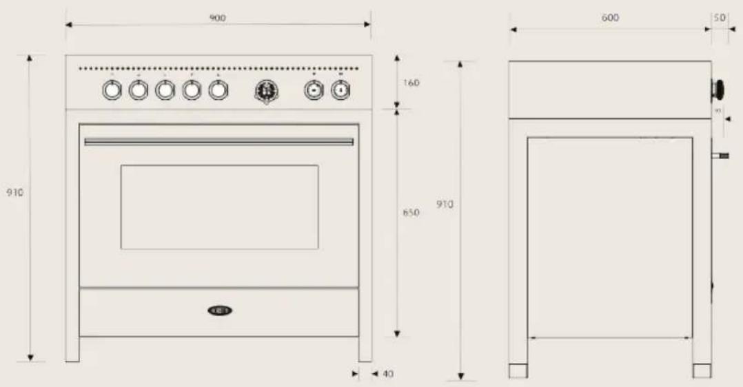
900 160 650 910 40 600 503.1 General warnings
the following operations must be carried out by a qualified installing technician. The installing technician is responsible for correctly installing the appliance according to current safety standards. Before using the appliance, remove the protective plastic on the control panel, stainless steel parts, etc...
After installation the installer must fully test the appliance and ensure it operates correctly before handing it over to the customer. The manufacturer declines any responsibility for damage incurred by persons, animals or objects that is caused by not following the above guidelines (cfr. chapter "2. Warnings for safety and use").
The technical data is indicated on the plate located on the back of the appliance. The adjustment conditions are shown on a label applied to the packing and the appliance.
Note:
Do not use the oven door handle for lifting or handling, including while unpacking the appliance.
3.2 Replacing the adjustable feet
The cooker comes with standard feet, already installed.
To raise the cooker, you should install feet blocks (optional accessories) to raise the working height of you cooker to the desired level.
Before tilting the cooker over, we recommend removing all the parts that are not stably attached to it, in particular the cooking hob grids and burners. To lighten the weight of the cooker, the accessories inside the oven may also be removed, thereby preventing accidental damage during the overturning operation.
Proceed in either of the following ways to replace the feet:
A - Lifting the cooker off the floor.
B - Laying the cooker on its back.

text_image
A BRemove the feet from the packing and screw them to the bottom of the cooker. Make the final adjustment of the feet, to level the cooker to the floor, after completing the gas and electrical connections.
i Should you need to drag the equipment, tighten the feet all the way and then adjust them after placing it where expected.
3.3 Electric Connection
Make sure that the voltage and capacity of the power line conform to the data shown on the plate located on the back of the appliance; a copy is attached to the manual. A second plate, including detailed information about the model and serial number, is placed inside the equipment on the left side and is visible on opening the oven door. These plates must never be removed.
Prepare an omni-polar cut-off device on the power supply line of the appliance with a contact opening distance equal to or more than 3 mm, located in a convenient position near the appliance.
Note:
Do not use reducers, adapters or shunts.
Before making the electric connection, make sure of the efficiency of the earthing. Make sure that the relief valve and the home wiring system are able to withstand the appliance load. The yellow/green earth cable must not be subject to cut-offs. The electric cable must not come into contact with parts whose temperature is more than 50^ C higher than room temperature.
3.3.1 Electric power cable section
According to the type of power supply, use a cable that conforms to the following table.
text_image
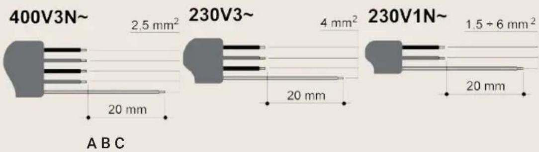
400V3N~ 2.5 mm² 230V3~ 4 mm² 230V1N~ 1.5 ÷ 6 mm² 20 mm 20 mm 20 mm A B CRunning at 400V3N\~ (models connected according to DIAGRAM "A"): use a pentapolar cable type H05RR-F (cable measuring 5 x 2.5 mm²).
Running at 230V3\~ (models connected according to DIAGRAM "C" but commutated by the installer according to DIAGRAM "B"): use a tetrapolar cable type H05RR-F (cable measuring 4 x 4 mm ^2 ).
Running at 230V1N\~ (models connected according to DIAGRAM "C"): up to 2.9 kW use a tripolar cable type H05RR-F (cable measuring 3 x 1.5 mm²); between 2.9 kW and 5.4 kW use a tripolar cable type H05RR-F (cable measuring 3 x 2.5 mm²); between 5.4 kW and 7 kW use a tripolar cable type H05RR-F (cable measuring 3 x 4 mm²); over 7 kW use a tripolar cable type H05RR-F (cable measuring 3 x 6 mm²).
The end to be connected to the appliance must have the earth wire (yellow-green) at least 20 mm longer.
3.3.2 Type of power supply
It is possible to obtain different connections according to the voltage, simply by moving the unconnected cable ends on the terminal board as shown in the following diagrams. According to the model, consult the table "Connection to the terminal board".
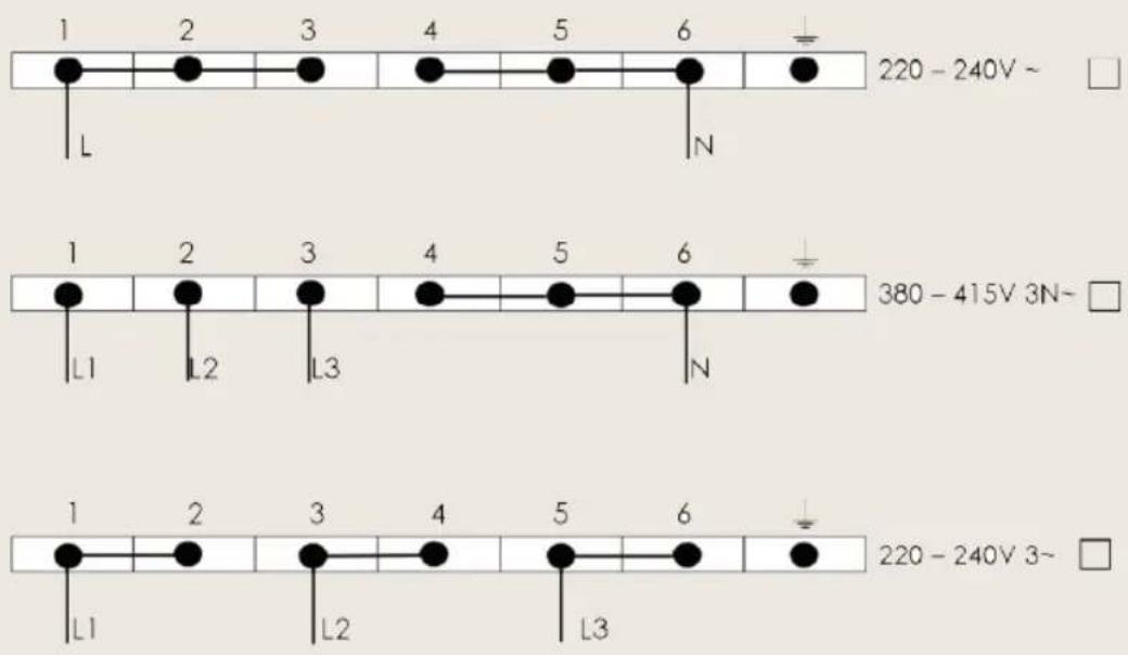
text_image
1 2 3 4 5 6 L N 220 - 240V ~ 1 2 3 4 5 6 L1 L2 L3 N 380 - 415V 3N~ 1 2 3 4 5 6 L1 L2 L3 220 - 240V 3~| Model Power kW |
| Gas Cooker - 6 Burners (1 Oven) 2,9kW |
| Induction Cooker – 5 zones (1 Oven) 10,3kW |
3.3.3 Replacing the electric cable
To replace the electric cable, it is necessary to access the terminal board. It is located on the back of the appliance as shown in the figure.
To replace the cable, proceed as follows:
* open the terminal board box;
* unscrew the screw A that locks the cable;
* loosen the screw contacts and replace the cable with one of the same length that corresponds to the
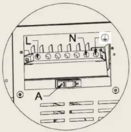
text_image
L N Aspecifications in the table in section "3.3.1 Electric power cable section";
* the "yellow-green" earth wire must be connected to the terminal and must be approximately 20 mm longer than the line cables;
* the neutral "blue" wire must be connected to the terminal marked with the letter N;
* the line wire must be connected to the terminal marked with the letter L.
3.4 Ventilation in rooms gas appliances
this appliance is not connected to an exhaust device for products of combustion. It must therefore be installed and connected in compliance with current installation standards. Pay particular attention to standards applied to room aeration.
This appliance can only be installed in ventilated rooms, according to current standards, so as to allow, with openings onto external walls or appropriate ducts, for correct natural or forced ventilation that permanently and sufficiently ensures both the air intake necessary for correct combustion and the expelling of vitiated air. It is recommended that the appliance have a rangehood fitted directly above or ceiling fan in close proximity to the appliance.
Note:
Using a gas cooking appliance produces heat and humidity in the room where it is installed. Ensure good room ventilation: keep natural ventilation grilles open or install a mechanical ventilation device (ducted extraction hood). Intensive and prolonged appliance use may require supplementary ventilation, for example, opening a window, more effective ventilation, or increasing the extraction hood power, if installed.
If this is the only gas appliance in the room, it is necessary to install a hood so as to expel vitiated air naturally and directly, with a rectilinear vertical duct at least twice as long as its diameter and having a minimum section of at least 100 ~cm^2 .
For the essential air intake into the room, it is necessary to prepare a similar opening of at least 100 cm2 that communicates directly outside, situated close to floor level so as not to be obstructed from either inside or outside and so as not to disturb the combustion of the burners and the correct expelling of vitiated air and with a height difference from the exit opening of at least 180 cm.
Remember that the quantity of air necessary for combustion must not be lower
than 2 m^3/h per kW of power (see total power in kW shown on the appliance plate).
In all other cases, i.e. when other gas appliances are present in the same room, or, if it is not possible to have natural direct ventilation, it is necessary to create natural, indirect ventilation or forced ventilation: for this type of operation, it is necessary to contact a qualified technician for installing and creating the ventilation system in strict compliance with the guidelines set out in current standards.
The openings should be positioned so as not to allow the formation of any unpleasant air current for the occupants. Furthermore, it is forbidden to use flues already used by other appliances to expel products of combustion.
3.5 Gas connection
Note:
The appliance's setting conditions are stated on the plate on the back of the appliance. Gas-powered devices for home use, which are not connected to a conduit for the evacuation of combustion products, must not cause a concentration of carbon monoxide that could pose a health risk to the persons exposed in relation to the time of exposure.
We recommend checking that the appliance is properly set up for the type of gas distributed. The connection to the gas pipes must be made in a workmanlike manner, in compliance with current standards that prescribe the installation of a safety tap at the end of the pipe. The threaded 12 " gas connection pipe is located at the rear on the right hand side of the appliance.
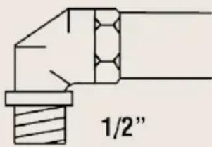
text_image
1/2"For butane and propane, a pressure reducer conforming to standards regulations UNI-CIG 7432 in force should be prepared. The seals must conform to standards regulations UNI-CIG 9264 in force. Once the gas has been connected, check the seal of the unions with a soap and water solution.
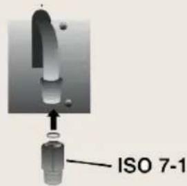
text_image
ISO 7-1
text_image
ISO 228-1| AT | ● | |
| BE | ● | |
| CH | ● | |
| DE | ● | |
| DK | ● | |
| ES | ● | ● |
| FI | ● | ● |
| FR | ● | |
| GB | ● | |
| IE | ● | |
| IT | ● | ● |
| LU | ||
| NL | ● | |
| NO | ● | ● |
| PT | ● | ● |
| SE | ● | ● |
It is possible to connect the gas in the following ways:
* using iron or copper rigid pipe;
* using uninterrupted stainless steel flexible pipe with a mechanical fitting conforming to standards regulation norm (maximum length of extended pipe 2000 mm). The pipe should be connected straight to the elbow of the ramp;
* by inserting a flexible rubber pipe conforming to regulation norm in force. This pipe should be coupled straight to the rubber-holder P corresponding to the gas used, and locked with a clamp F conforming to standards regulations in force. In the latter case, check the expiry date printed on the pipe and replace it before that date.
Using flexible rubber pipes with a max. length of 1500 mm:
* do not allow the pipes to be constricted or crushed;
* pipes must not be subject to tractive force or torsional stress;
* do not allow the pipes to come into contact with cutting or sharp edges, etc...
* do not allow the pipes to come into contact with parts that can reach temperatures of 70°C above room temperature;
* make sure the entire length of the pipes can be inspected;
* do not use the Natural Gas Regulator supplied with the appliance for Propane Gas.
Important:
In Belgium, in accordance with Belgian standards NBN D 51-003 and NBN D 51-006, the type of connection with elastomer hose (Flexible rubber pipe) is prohibited for cookers installed inside buildings.
Note:
The unit must be coated in heat-resistant material (minimum 90^ C). If the appliance is installed close to other units, the minimum space suggested in the following diagram must be left.
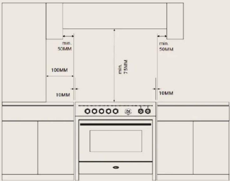
text_image
min. 50MM 100MM 10MM min. 75MM min. 50MM 10MM3.6 Gas adjustments
The injectors not supplied with the appliance should be requested from the Service Centre.
If the cooking appliance is set up for a different type of gas than that available, its injectors must be replaced, the minimum flow regulated and the rubber-holder changed. In order to replace the injectors in the cooking hob, it is necessary to carry out the following operations:
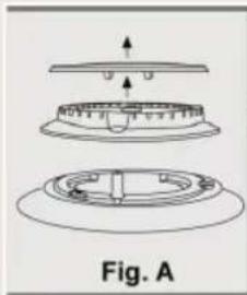
* remove the pan supports;
* remove the burners and burner caps (Fig. A);
* take out the injector (Fig. B / Fig. C) and replace it with one suitable for the new type of gas (see "GENERAL INJECTORS TABLE" on page 25, 25.);
* replace the gas label (on the rear of the appliance) with the new one provided with the injectors kit;
* refit all parts by following the disassembly instructions in reverse order and taking care to position the burner cap correctly on the burner.
natural_image
Technical diagram of a mechanical assembly with three views (top, front, side) showing internal components and alignment indicators, labeled Fig. A (no text or symbols on the diagram itself)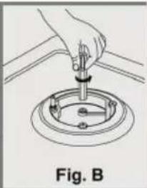
natural_image
Illustration of a hand using a tool to press or install a mechanical component, labeled Fig. B (no text or symbols on the diagram itself)
natural_image
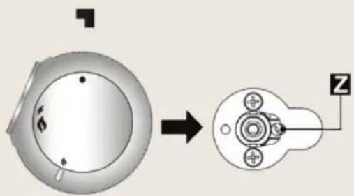
Close-up of a mechanical component with a wrench inserted, labeled Fig. C (no text or symbols on the object itself)3.6.1 Minimum flow of valved cooking hob taps
* Switch on the burner and turn the control knob towards the minimum flow position ;
* remove the knob;
* using a screwdriver, adjust the internal screw Z until the correct low flame is obtained;
* refit the knob.
* Unscrew the adjustment screw Z to increase the flow, or tighten it to reduce the flow.
* The adjustment is correct when the low flame measures approximately 3 or 4 mm.
* For butane/propane, the adjustment screw should be tightened all the way.
* When changing quickly from maximum to minimum flow and vice versa
natural_image
Mechanical component diagram showing a circular housing with mounting holes and a separate view of a mechanical assembly with a Z-shaped connector (no text or symbols)make sure that the flame does not go out.
3.7 Connecting to LPG
Warning:
Gas may only be connected to a gas installation, whether bottle supplied or other.
EE% 6 BURNERS
56.6
text_image
B B A A G D| EE% | RAPID (A) | SEMI RAPID (B) | WOK (G) | AUXILIARY (D) |
| 58.4 56.5 53.2 - | ||||
NL GENERAL INJECTORS TABLE (NL) - CAT: II 2EK3B/P
| Type of Gas mBar Nozzle | No. | Burners Position Type | Power Watt Consumption | |||
| Min. Max. | Max. | |||||
| G25 / G25.3 NATURAL GAS | 25 | 121 | RAPID (A) | 3000 | 750 | 332 l/h |
| 94 | SEMI RAPID (B) | 1750 | 480 | 194 l/h | ||
| 135 | WOK BURNER (G) | 3500 | 1800 | 387 l/h | ||
| 72 | AUXILIARY (D) | 1000 | 330 | 111 l/h | ||
| BUTANE G30 PROPANE G31 | 28/30 37 | 85 | RAPID (A) | 3000 | 750 | 219 g/h |
| 65 | SEMI RAPID (B) | 1750 | 480 | 128 g/h | ||
| 94 | WOK BURNER (G) | 3500 | 1800 | 254 g/h | ||
| 50 | AUXILIARY (D) | 1000 | 330 | 73 g/h | ||
BE GENERAL INJECTORS TABLE (BE) - CAT: II 2E+3+
| Type of Gas | mBar Nozzle No. | Burners Position Type | Power Watt | Consumption | ||
| Min. | Max. | Max. | ||||
| G20/G25 NATURAL GAS | 20/25 | 115 | RAPID (A) | 3000 | 750 | 286 l/h |
| 97 | SEMI RAPID (B) | 1750 | 480 | 167 l/h | ||
| 132 | WOK BURNER (G) | 3500 | 1800 | 333 l/h | ||
| 72 | AUXILIARY (D) | 1000 | 330 | 95 l/h | ||
| BUTANE G30 PROPANE G31 | 28/30 37 | 85 | RAPID (A) | 3000 | 750 | 219 g/h |
| 65 | SEMI RAPID (B) | 1750 | 480 | 128 g/h | ||
| 94 | WOK BURNER (G) | 3500 | 1800 | 254 g/h | ||
| 50 | AUXILIARY (D) | 1000 | 330 | 73 g/h | ||
4. Description of control
4.1 Control panels
All the commands and controls for the cooking hob and oven are on the front panel.
Gas cookers, 6 Burners (1 Oven)
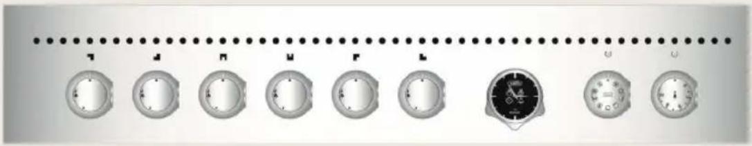
text_image
T M N F L U UInduction cookers, 5 Zones (1 Oven)
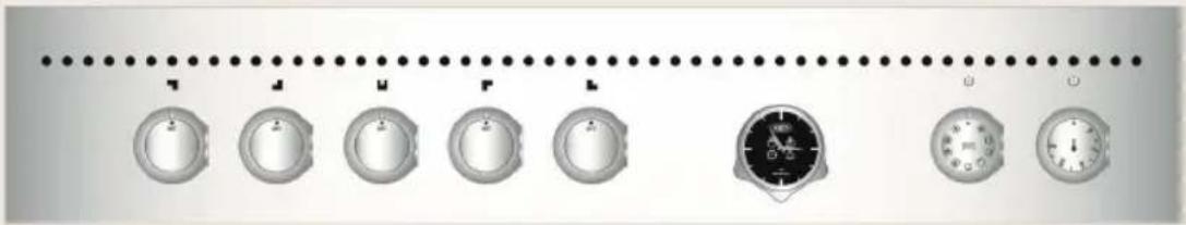
natural_image
Row of circular gauges with a central dial and a speedometer, all aligned with a dotted line above (no text or symbols on the gauges themselves)Description of Burner knob
The flame is lit by simultaneously pressing and turning the knob anticlockwise to the low flame symbol. To regulate the flow of the flame, turn the knob to between the maximum and minimum settings. Turn off the burner by returning the knob to position.
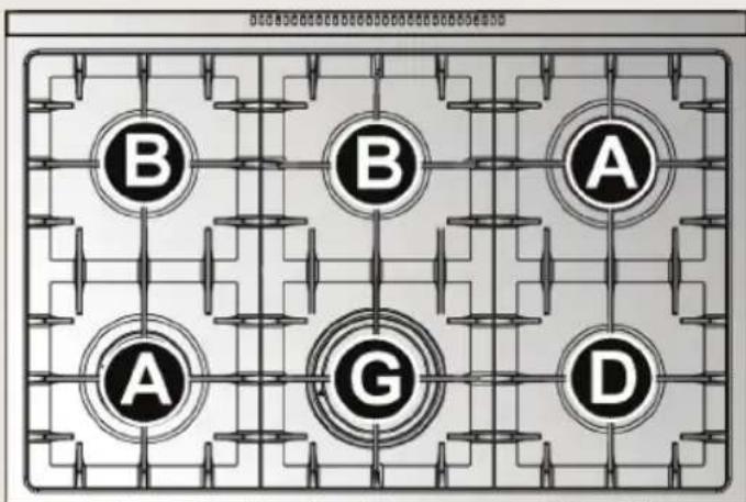
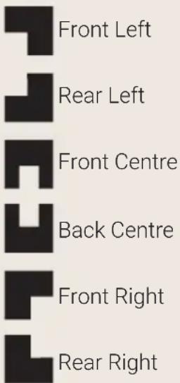
Layout of Burners – Description of symbols

Front Left

Rear Left

Front Centre

Back Centre

Front Right

Rear Right
Description of induction hob
The induction hob is fitted with knobs for controlling the power level. To select a different power level, turn the control knob to the required value (1 - 9 and P). "P" is the maximum power applicable to each radiant element.
Note:
Turn the knob to set the desired power value (see table in section "7.2"). Turn the knob to display the actual desired power level, whereas the one selected with the knob is only indicative.
Layout of radiant elements – Description of symbols
text_image
Front Left Rear Left Front Centre Back Centre Front Right Rear RightAll the controls for the radiant elements are located on the front panel and the relative displays are visible on the hob
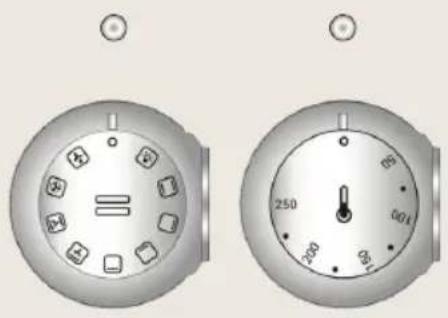
Description of electric oven knobs
The electric oven is controlled by two knobs: function switch knob and thermostat knob. They allow you to choose the most suitable type of heating for different cooking requirements, by switching on the heating elements appropriately and setting the required temperature (50°C to 250°C).
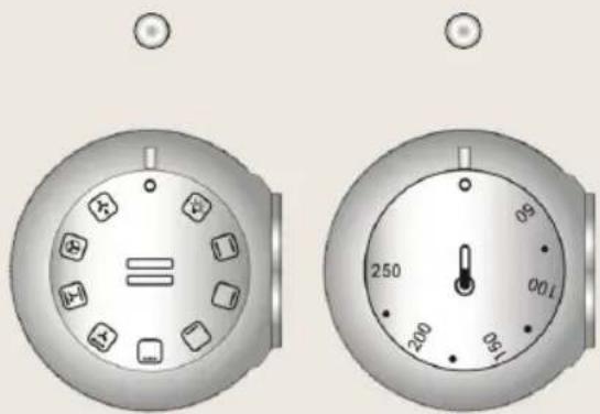
Above the oven knobs there are two warning lights: the left white light signals the oven is working; the white right light indicates that the preset temperature has been reached. The white light switches on and off to indicate when the heating automatically kicks in to maintain the temperature inside the oven at the level set on the thermostat knob.
The oven has an internal light. The light is always on while the oven is working: it can be switched on while the oven is off, for cleaning purposes, by turning the function switch knob to the symbol.
Description of symbols on the function switch knob

Switch on Light inside oven

Conventional Cooking - Upper + Lower heating element - ECO (See paragraph 8.3.1)

Upper heating element

Lower heating element

Grill element

Grill fan element

Conventional Cooing + fan

Heating element - Convection

Defrost
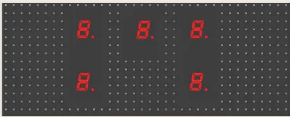
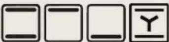
Using and programming the digital analogue clock on ovens
The digital clock enables the oven to be set to automatically switch on and off.
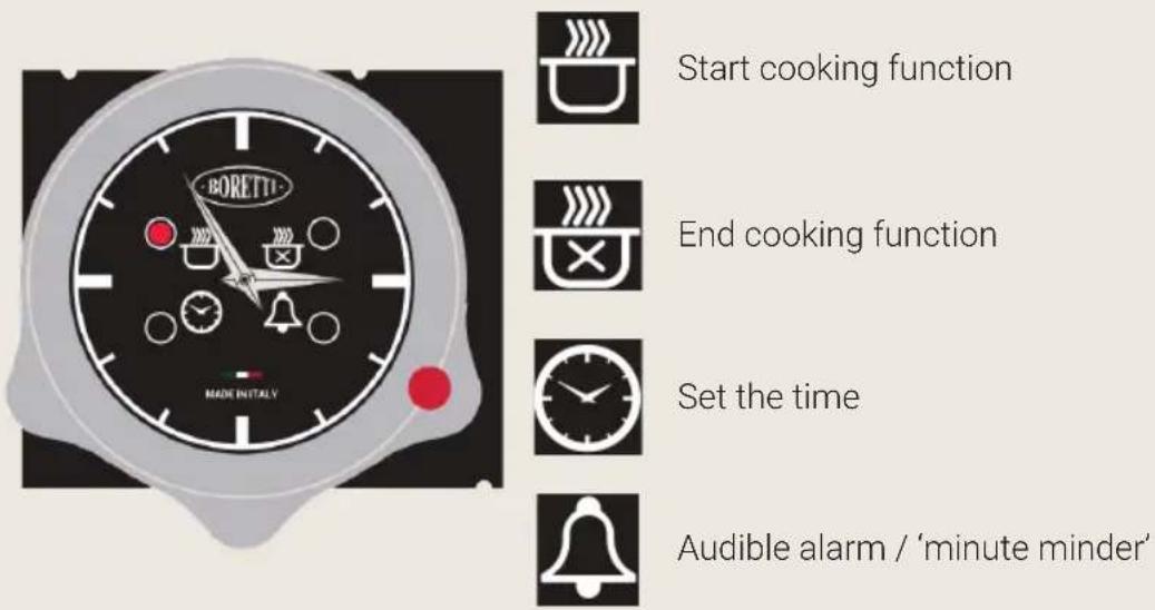
Start cooking function
End cooking function
Set the time
Audible alarm / 'minute minder'

The push knob is used to set the time, program cooking start and end times, set the audible alarm (in "Minute Minder" mode) and start/stop cooking manually.
Setting the time
Proceed as follows:
* Press the push knob 4 times until the LED flashes;
* Turn the push knob clockwise or anticlockwise to increase or decrease the time; the minutes hand moves in 1-minute stages clockwise or anticlockwise.

The clock automatically exits time-setting mode 10 seconds after last turning the push knob.
Cooking in manual mode
For using the oven without programming the electronic clock.
When the electronic clock is deactivated, the ovens may be used simply by turning the appropriate control knobs (see the relative sections 7.3).
Programming cooking end time
After programming the cooking end time, the oven will switch on immediately
and turn off automatically at the set time.
Proceed as follows:
* Press the push knob 2 times until the 📋 LED flashes;
* Turn the push knob clockwise or anticlockwise to increase or decrease the cooking time; the minutes hand moves in 1-minute stages clockwise or anticlockwise. The LED 🎨 will keep flashing for 10 seconds after last turning the push knob.
i Confirm the programmer by pressing the push knob (minimum programming time: 1 minute of cooking).
* An audible alarm will automatically activate. The oven will switch on immediately and switch off automatically when the set cooking end time coincides with the current time.
i To display the set programme, press and release the push knob (the hands and the LEDs will display the set programme).
* At the end of cooking, the LED 🎨 will flash and the alarm sounds for 1 minute (press the push knob to deactivate it).
To cancel the programme before the end of cooking, press the push knob for 3 seconds; the programme will be cancelled and the electronic clock will return to manual cooking mode.
Programming cooking start and end times
Programming the cooking start time enables cooking to start and end automatically based on the programme.
To programme the cooking start time, proceed as follows:
* Press the push knob once until the 📄 LED flashes;
* Turn the push knob clockwise or anticlockwise to increase or decrease the cooking start time; the minutes hand moves in 1-minute stages clockwise or anticlockwise. The 🎨 LED will keep flashing for 10 seconds after last turning the push knob.
i If the push knob is not turned or pressed within 10 seconds, the hands
will automatically return to the current time and the programme will be cancelled.
* On pressing the push knob, the cooking start time will be stored (LED on and steady) provided at least 1 minute's delay has been programmed and the cooking end time* is now set (LED will go from off to flashing). The oven will switch on automatically when the set cooking start time coincides with the current time.
i To programme the cooking end time, follow the procedure given in the previous section on page 31.
Programming the alarm
Programming the audible alarm produces a beep at the end of the cooking programme, or at the end of the set time if no cooking has been activated (in "Minute Minder" mode).
When starting a programme with the cooking start time and cooking end time activated:
* The audible alarm activates automatically (☐ LED on). To deactivate it, press the push knob after programming the cooking end time.
To set the audible alarm to beep without activating cooking (in "Minute Minder" mode), proceed as follows:
* Press the push knob 3 times until the 🔊 LED flashes;
* Turn the push knob clockwise or anticlockwise as described in section "Programming cooking end time".
i "Minute Minder" mode can only be used when no cooking programme is set.
5. Using the gas hob
i Make sure that the flame caps, the burner caps and the pan supports are fitted correctly.
Note:
During normal operations, the appliance heats up considerably. Caution should therefore be used. Do not allow children to approach the appliance. Do not leave the cooking hob unattended while it is on.
5.1 Switching on the burners
All the hob burner knobs have the following symbols:
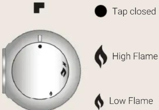
Tap closed
High Flame
Low Flame
The low flame setting is found by turning the knob anticlockwise all the way. All intermediate settings must be selected between the high flame and low flame, never between high flame and closed.
i Using the burner with dual-crown flame-spreader: if while using the hob you notice the flame changes consistency or sputters between the central and outer crowns of the burner, this is due to the continuous power required by this type of burner and should be considered as normal.
5.1.1 One-touch lighting
The hob burners are equipped with a "one-touch" lighting system. To switch on one of the burners, press the knob corresponding to the required burner and turn it anticlockwise to the low setting. Hold down the knob to activate the automatic "one-touch" lighting system. When the burner is on, hold down the knob for approximately 10 seconds, to allow the safety valve to open. In the event of a power cut, the burner can also be lit with a match (see section "5.1.2 Manual lighting"). Should the burner switch off accidentally, the safety thermocouple blocks the gas flow, even when the tap is open.
Caution:
The device should not been activated for longer than 15 seconds. If after that time it fails to operate stop pressing the knob, open the window and wait 1 minute before trying again. In case the flame goes out accidentally turn off the knob and do not try to switch on the burner for at least 1 minute.
5.1.2 Manual lighting
To light one of the burners, move a lit match towards the burner, press the corresponding knob and turn it anticlockwise to the minimum setting 🔒. Release the knob.
5.2 Switching off the burners
At the end of the cooking, return the knob to position
6. Using the induction hob
The hob is equipped with one radiant generator per cooking zone. Each generator located below the glass ceramic cooking surface generates an electromagnetic field that induces a thermal current in the base of the pan. In induction cooking, heat is not transmitted from a heat source, but created by inductive currents directly inside the pan.

Advantages of induction cooking:
* Energy saving thanks to the direct transmission of energy to the pan, compared with traditional electric or gas cooking.
* Safer thanks to the transmission of energy solely to the pan rested on the hob.
* Highly efficient energy transmission from the induction cooking zone to the base of the pan.
* Rapid heating speed.
* Reduced risk of burns, since the cooking surface is heated solely at the base of the pan.
* Spilt food does not stick to the surface of the hob.
6.1 General warnings
- Remove all labels and self-adhesives from the ceramic glass.
- Before connecting the appliance to the mains, ensure it has been standing at oom temperature for at least 2 hours.
- People with a pacemaker or other similar devices must ensure that the operation of their devices is not jeopardised by the induction field, the frequency range of which is between 20 and 50 kHz.
- Do not wear metal objects or necklaces in direct contact with the body. When entering the radiating field of the induction hob, they may overheat with an ensuing risk of scalding. Non-magnetisable metals (e.g. gold or silver) do not carry this risk.
- Objects with a magnetic strip (credit cards, swipe cards, floppy discs, etc.) must not be left near the appliance while it is on.
- Do not heat canned food or other sealed containers. The pressure that builds up inside the container during cooking may cause it to explode.
-
Do not place metal objects such as cookware or cutlery on the surface of the hob as they can overheat, with an ensuing risk of scalding.
-
Never cover the appliance with a cloth or a protection sheet. this is supposed to become very hot and catch fire.
-
Do not use the glass surface of the hob as a countertop or work surface.
-
Make sure no cable of any fixed or moving appliance contacts with the glass or the hot saucepan.
-
Any damage arising from the use of saucepans unsuitable for induction cooking, or of removable accessories between the pan and the radiant element, will void the warranty. The manufacturer cannot be held liable for damage to the hob or related damage arising from improper use.
6.2 Automatic radiant power distribution
The maximum applicable power is distributed among the active radiant elements, the last power level set takes priority over the previous settings on the other radiant elements.
Power is distributed automatically among the three radiant elements on the left (A) and the two on the right (B).
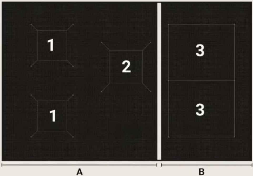
text_image
1 2 1 A 3 3 B| A | B | ||
| Radiant Element | 1∅ 200 MM | 2∅ 230 MM | 3Π 220 x 200 MM |
| Power 1850 | W 2300W 2100W | ||
| Power with Booster | 3000W | 3700W | 3700W |
| Maximum power | 3700W | 3700W | |
| Power Level | 1 2 3 4 5 6 7 8 9 | |||||||
| Radiant 1 | 55w | 120w | 203w | 287w | 351w | 583w | 832w | 1193w |
| Radiant 2 | 69w | 149w | 253w | 356w | 437w | 724w | 1035w | 1483w |
| Radiant 3 | 63w | 136w | 231w | 235w | 399w | 661w | 945w | 1354w |
When using several radiant elements simultaneously, the last activated element may maintain the set value to the detriment of the other previously set elements, which may then be affected by a reduction in power. On activating the last radiant element, the values on the displays of the previously set elements, will start to flash, automatically showing the new lower power level supplied. If the heating value of any of the radiant elements is manually reduced, the difference in power will be redistributed among the remaining elements.
i Given that cooking will continue with new, automatically reset power values, adjustments may need to be made depending on the type of food being cooked.
6.3 Energy regulator table
the table below indicates the power levels that can be set and the type of food that can be cooked at each level. The values may vary depending on the quantity of food and personal taste.
i Turn the knob to set the desired power value. Turn the knob to display the actual desired power level, whereas the one selected with the knob is only indicative.
| 1 - 2 | For heating food, keeping small quantities of water on the boil, making egg-or butterbased sauces. |
| 3 - 5 | For cooking solid and liquid food, keeping water on the boil, defrosting frozen food, frying 2-3 eggs, cooking fruit and vegetables, general cooking. |
| 6 - 8 | Cooking meat, fish and vegetable stews, food with more or less water, making jams, etc. |
| 9 | Roasting meat or fish, steak, liver, browning meat or fish, eggs, etc. |
| P | Deep fat frying potatoes etc., bringing water rapidly to the boil. |
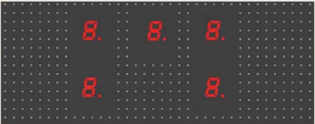
6.4 Switching on the induction hob for the first time
Clean the hob with a damp cloth, and then dry the surface thoroughly. Do not use detergent which risks causing blue-tinted colour on the glass surface.
When the hob is first switched on the displays of all the radiant elements light up simultaneously displaying the symbols B as shown in the figure; the displays will then switch off immediately without emitting any sound.
natural_image
Five identical circular buttons with 'OK' labels, arranged horizontally (no text or symbols on the buttons themselves)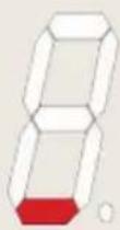
If one or more knobs is not in "0" position when the hob is first switched on, the relative displays light up as normal, but the radiant element will not work. On turning the knob, the relative display will show the adjacent symbol, signalling the radiant element failed to work. The element will only work properly again once the knob is returned to "0" position and a new power value is set.
6.5 Pan recognition
an electronic sensor detects if a pan is present or absent on the radiant element. If the type of pan is unsuitable for magnetic induction cooking (see section "6.5") or if the pan is too small (see table "MINIMUM DIAMETER" the adjacent symbol is displayed.
If during cooking a pan is removed from the radiant element without having first returned the relative knob to "0" position, the power value, previously set and shown on the relative display, will be automatically replaced with the symbol
If the pan is repositioned correctly on the radiant element, the symbol switches off and cooking will resume normally; otherwise, after 10 minutes, the symbol will switch off, the knob will have to be returned to "0" position and a new power value set before the radiant element can be used again.
If a knob is turned to any position before placing a pan on the radiant element, the relative display shows the set power value and then immediately replaces it with the symbol U (the radiant element stands by for 10 minutes). If in the meantime a pan is placed correctly on the radiant element, cooking will begin; otherwise the radiant element does not activate and symbol U switches off. To reactivate the radiant element, the relative knob must be returned to "0" position and a new power value set.
Pan recognition limits: the diameter of the pan base is signalled by a circumference or perimeter on the cooking zone.
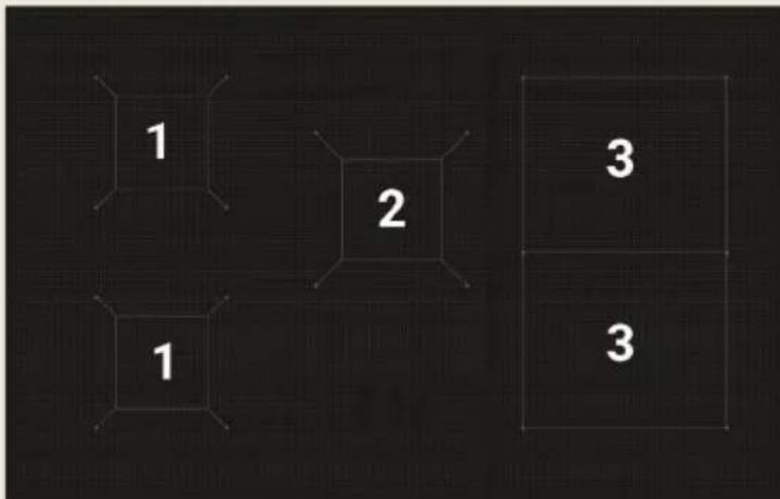
text_image
1 2 3 1 3| 1 2 3 | ||
| DIAMETER MINIMUM (MM) | 145 180 145 | |
| DIAMETER MAXIMUM (MM) | 200 230 220 |
6.5.1 One-touch lighting
Manufacturers generally state whether or not their cookware is suitable for induction cooking. The adjacent pictogram indicates the kind of symbol used to denote suitability for induction cooking, usually found on the bottom of the pan.
Only use pans with perfectly flat, smooth bases suitable for induction cooking.
The cookware used for induction cooking must be made of ferrous alloys or ferritic steel, be magnetisable and have a sufficiently thick base.
To check whether the pan is suitable, simply hold a magnet at its base: if it is attracted the pan is suitable for induction cooking. If you do not have a magnet, pour a little water into the pan, rest it on a cooking zone and turn on the hob.
Certain pans can make noise when they are placed on an induction cooking zone. This noise doesn't mean any failure on the appliance and doesn't influence the cooking operating.
| SUITABLE COOKWARE UNSUITABLE COOKWARE | |
| * Enamelled ferritic steel cookware with thick base. | * Copper, stainless steel, aluminium, fireproof glass, wood, ceramic and terracotta. |
| * Ferrous cast iron cookware with enamelled base. | |
| * Multilayer stainless steel, stainless ferritic steel or aluminium cookware with special base for induction cooking. | |
6.6 SWITCHING ON A RADIANT ELEMENT
Before activating a radiant element, place a suitable pan on the relative cooking circumference.
On turning any knob clockwise, a beep is emitted and all the displays switch on; the one corresponding to the turned knob will show the selected power value, while the others will show the value ☐.
On turning a second knob, no beep is emitted and the display shows the power value set for that knob.
6.6.1 Changing the power level
Each knob has a graduated scale increasing clockwise from level "0" to level "9". The heating power of the radiant elements is increased by turning any knob clockwise from "0" position, and is decreased by turning the knob anticlockwise from the position reached.
The knob's default position corresponds to level "0" (value 0. on the relative display).
i Turn the knob to set the desired power value (see table in section "6.2"). Turn the knob to display the actual desired power level, whereas the one selected with the knob is only indicative.
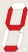
Turning knob clockwise beyond power level "9" will result in a click and an audible signal, which will enable the "Booster" function indicated on the display with the symbol P; then reposition the knob on level "9" (see paragraph "6.6.3").
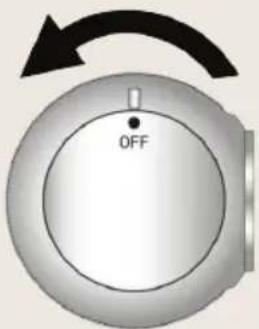
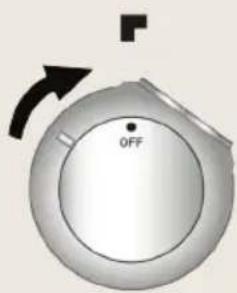
6.6.2 Rapid heating function
This function enables the required power level to be reached more quickly, although it remains active for a very limited period of time. Starting from "0" position, turn the knob anticlockwise until it clicks and hold it in that position for 2 seconds; the display will light up showing the adjacent symbol. You will then have 10 seconds to turn the knob to the required power level; the display will start flashing alternating symbol A, with the new power level set with the knob.
text_image
OFFThe following table gives the rapid heating times to the various power levels.
| Selected Power Level | 1 2 3 4 5 6 7 8 | 9 | |||||
| Duration in seconds | 48 144 230 312 408 120 168 216 | - |
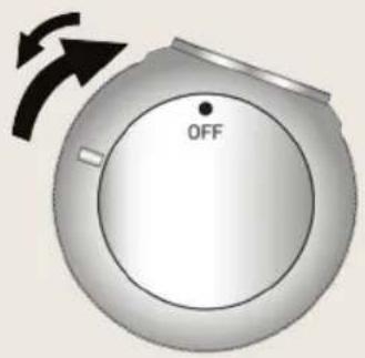
6.6.3 Booster function
Turn the knob clockwise beyond power level "9" until you hear a click and an audible signal (the display shows the adjacent symbol); then reposition the knob on level "9".
The knob must be correctly repositioned on level "9"; otherwise the symbol P, shown on the display, will be replaced by error code which signals deactivation of the radiant element; to restore
text_image
OFFthe radiant element, follow the instructions given in paragraph "6.10". The maximum heating time with the Booster function is 10 minutes. At the end of the maximum heating time, symbol P flashes for a few seconds and the power is automatically reset, displaying the value 9. With the Booster function activated, several consecutive cycles can be repeated.
6.6.4 Food Warming function
This function warms to 45^ C the bottom of a pan suitable for induction cooking maintaining a constant temperature (*) inside the pan; it is useful for keeping previously cooked food warm inside the pan, thus optimising energy consumption. The maximum time for constant warming is limited to 120 minutes.
The first 3 power levels are food warming functions. Turn the knob clockwise and the symbols will be indicated on the induction surface.
text_image
OFFThe corresponding display shows the adjacent symbol in three phases (heating power is automatically adjusted).
| Phase | 1 2 3 |  |  |  |
| (*) Constant temperature | 42°C 70°C 94°C | |||
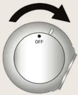
6.6.5 Bridge function
This function "bridges" the two right-hand radiant elements (front and back) into a single cooking zone controlled only by the second knob on the right. The Booster function cannot be used when the Bridge function is active.
Simultaneously turn the last two knobs on the right clockwise (beyond power level "9" until they click and a beep is emitted) until position "P" and hold them in this position for at least 2 seconds (the corresponding displays show the adjacent symbols signalling the function is active). Turn the second knob on the right to the desired power level.
text_image
OFF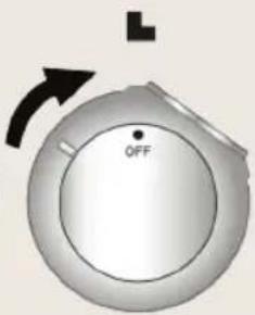
text_image
OFFIf a pan is removed from the radiant elements during cooking and not replaced within 10 minutes, the function automatically deactivates.
To deactivate the function manually, return the knobs to "off" position.
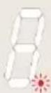
6.6.6 Residual heat
After cooking is finished and the knob is returned to "off" position, the radiant element's display shows the adjacent symbol alternated with the value 0, indicating that that radiant element has just been used and is still hot.
The symbol H will flash for a few seconds, then will become steady and will stay on until the glass temperature has gone below the safety level.
6.6.7 Ventilation
The cooling system is fully automatic. The cooling fan starts with a low speed when the calories brought out by the electronic system reach a certain level. The ventilation starts his high speed when the hob is intensively used. The cooling fan reduces his speed and stops automatically when the electronic circuit is cooled enough.
6.6.8 Overheating
The induction hob is fitted with a safety device that protects the internal electronics against overheating. This device requires no attention from the user and enables the hob to be used confidently without the risk of overheating.
6.6.9 Deactivating a single radiant element

On turning any knob anticlockwise and keeping it in that position for more than 30 seconds, the relative display will show the adjacent symbol to indicate the radiant element is deactivated.
If the knob is not positioned correctly, the relative display will show error code which signals deactivation of the radiant element. It is not necessary to call Customer Service; to restore the radiant element, simply return the knob to position "0" and reset the required power value.
This function is advisable to disable a single radiant element if it is faulty or malfunctioning. After the radiant element has been repaired by the authorised Technical Support Service, it can be reactivated by turning the knob anticlockwise again and keeping it in that position for more than 30 seconds.
6.7 Automatic switch off
an automatic counter counts the time elapsing since the last power variation. This determines the maximum heating duration, which varies according to the power level selected. If a radiant element is left on by mistake (with a correctly positioned pan), it will switch off automatically once the maximum heating duration for the selected power is reached.
| Selected power level | 1 2 3 4 5 6 7 8 9 P |
| Max time in minutes | 360 300 240 90 90 90 90 10 |
6.8 Switching off manually
Turn all the knobs to "off" position. Each display will show a flashing dot as in the adjacent figure; after 15 seconds all the displays will switch off, a beep will be emitted and the appliance with go to stand-by.
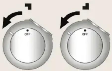
6.9 Child safety
the radiant elements can be deactivated. Turn the first two knobs on the left anticlockwise simultaneously and keep them in this position for least 2 seconds, until all the displays show symbol L. After a few minutes the symbols L switch off, but the radiant elements will not
text_image
OFF OFFactivate and the above-mentioned lock symbols appear on all displays if any knob is turned.
The deactivation has no time limit. A prolonged power failure may cancel this deactivation.
To reactivate the radiant elements, turn the first two knobs on the left anticlockwise simultaneously.
6.10 In the event of faults and failures
if a defect is noticed, switch off the appliance and turn off the electrical supplying.
Do not attempt to use a faulty radiant element until it is repaired by the authorised Technical Support Service.
Any repairs must be carried out exclusively by qualified personnel. Do not open the appliance for any reason.
If the glass surface is damaged, switch off the appliance immediately to prevent the risk of electric shocks and contact the Technical Support Service.
If a radiant element is faulty, the remaining elements can still be used normally. To clear the error code from the displays, set all the knobs to "off" position and set new power values.
The following list includes the most frequent failures, the causes of which can be removed by the user or via the Technical Support Service.
| FAULT CAUSE REMEDY | ||
| The hob or the cooking zones do not switch on. | The appliance is not correctly connected to the mains.The hob lock function has been activated. | Reconnect the appliance to the mains.Deactivate the lock by following the instructions in section 6.9 |
| The display shows the adjacent symbol. | There is no pan on the cooking zone.The pan is not suitable for magnetic induction cooking.The diameter of the base of the pan is too small for the cooking zone. | Correctly position a suitable pan by following the instructions in section 6.5Replace the pan with a suitable one, as indicated in section 6.5Replace the pan with a suitable one, as indicated in section 6.5 |
| The display shows the adjacent symbol. | The knob is not positioned correctly. | It is not necessary to call Customer Service; to restore the radiant element, simply return the knob to position "0" and reset the required power value. |
| The display shows the adjacent code alternated with numbers or letters. | Contact Customer Service and give the code shown on the display. | |
| The hob or a cooking zone switches off. | The safety device has triggered.The device triggers when a cooking zone is left on by mistake.An empty pan has overheated. | Return the relative knob to "off" position.Remove the empty pan from the cooking zone. |
| The cooling fan stays on after the hob is switched off. | This is not a fault. The fan stays on until the hob has cooled down.The fan will switch off automatically. | |
7. Using the oven
7.1 General warnings
- When the oven or grill is operating, the outer walls and oven door can become very hot. Keep children away from the appliance.
- Do not allow children to sit on the oven door or play with it.
- Do not use the door as a stool.
- Never stand aluminium pots or foil on the base of the oven, as this may seriously damage the oven enamel.
- Do not cook food on the bottom of the oven.
- Do not attempt to disassemble the oven door without consulting the relative instructions carefully (refer to section "10.1 Removing the oven door"): the hinges on the oven door may injure the hands.
i Heating block of the oven
If during normal operation the oven interrupts heating and the programmer display begins to flash and goes to zero, check whether:
* there has been a current interruption.
If the block occurs again after the cooking programme has been restarted, this means that the safety device has been tripped. This device intervenes in the event of a thermostat fault and prevents oven overheating. In such case, we recommend that you not try to light the oven again and that you contact your nearest service centre.
7.2 Risk of condensation
* Some cooking with high water content combined with the use of certain functions can cause the formation of condensation on the door's inner glass. To prevent this occurring, open the oven door for a few seconds once or twice while cooking.
* Do not leave food to cool in the oven after cooking to prevent condensation forming on the door's inner glass, which may drip out of the oven when the door is opened.
7.3 Using the electric multifunction oven
7.3.1 Switching on the oven for the first time.
The first time it is used, the oven may smoke or give off an acrid smell caused by oily residue from manufacturing that may give unpleasant odours or flavours to food. Before putting food in the oven, heat to the maximum temperature for 30-40 minutes with the door closed and wait until the smoke or odour has stopped.
natural_image
Two identical circular gauges with internal symbols, shown from different angles (no text or labels visible)To prevent any steam in the oven from scalding, proceed as follows: turn the function switch knob to position '0', or to function ☐; open the door in two stages: hold it partly open (approx. 5 cm) for 4-5 seconds, then open it completely. Should you need to adjust the food, leave the door open for as short a time as possible to prevent the temperature inside the oven from lowering to such an extent as to jeopardise cooking.
Power elements
Upper + Lower heating element: 2080W
Upper element: 880W
Lower element: 1230W
Circular element: 2170W
Grill element: 1950W
7.3.2 Traditional cooking
Turn the function switch knob to position and the thermostat knob in correspondence with the required temperature value. For differentiated heating over or below the food, set the function selector switch to position (upper heating) or (lower heating). For more uniform heating throughout all cooking levels in the oven, turn the function switch knob to position Y.
Recommended for both upper + lower heating: Oven dishes, Cakes, Pies.
Recommended for lower heating: Souffle
Recommended for upper heating: Pot pies / Quiche
7.3.3 Convection cooking

Turn the function switch knob to position turn the thermostat knob in correspondence with the required temperature value. The circular element and the fan are on. The heat will equally distributed on each cooking level. The temperature must be regulated between 50°C and 250°C.
Recommended for: Oven dishes and Lasagna
7.3.4 Cooking with the ventilated grill

Turn the function switch knob to position ;turn the thermostat knob in correspondence with the maximum temperature value.
Recommended for: Oven dishes that need a crunchy top.
7.3.5 Cooking with grill

Turn the function switch knob to position ; turn the thermostat knob in correspondence with the maximum temperature value.
Recommended for: Vegetables, Fish.
7.3.6 Cooking with grill + roasting spit

If your oven model has a roasting spit, proceed as follows:
* Slide the meat to be cooked on the spit rod A and secure it with the adjustable forks.
* Hang the hook B at the top of the oven as shown in the figure.
* Place the spit rod A into the hole C in the oven casing; before closing the oven door, make sure that the rod A is correctly inserted into the hole C
(insert the rod and turn it slightly back and forth).
* Hang the other end of the spit rod to the hook B (the pulley of the rod A is situated on the handle of the hook B).
* Close the oven door and activate the spit by turning the function selector knob to the position.
* When cooking is completed, open the oven door and remove the spit rod
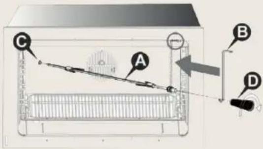
text_image
Diagram of a heating system with labeled components A, B, C, and D showing connections and a pressure gauge.using the plastic handle D, which is screwed into the base of the rod A. Recommended for: Roasted chicken, roulades, Porchetta
7.3.7 Defrosting
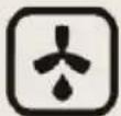
Turn the function switch knob to position 🙏 turn the thermostat knob to position 0: in this way the motor fan is activated, which moves the air inside the oven and encourages frozen food to defrost.
7.3.8 Switching off the oven
The oven is switched off by returning the thermostat knob to position 0.
8. Cooking suggestions
8.1 Suggestions for using the hob burners correctly
The diameter of the base of cooking recipients should fit the diameter of the burner used (see adjacent table). The burner flame must never be wider than the diameter of the recipient. Use recipients with a flat base. Where possible use pots with a lid, as this allows less power to be used. To reduce cooking times for vegetables, potatoes, etc., use little water.
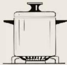
natural_image
Line drawing of a cooking pot on a gas stove (no text or symbols)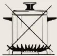
natural_image
Line drawing of a cooking pot with stirrer and crossed panes (no text or symbols)| BURNER RECIPIENT DIAMETER (IN CM) | |
| Rapid From 24 to 26 | |
| Semi rapid From 16 to 22 | |
| Auxiliary From 8 to 14 | |
| Triple-ring / Wok From 24 to 26 | |
8.2 Suggestions for using the induction hob correctly
For best cooking results and energy saving, only use cookware suitable for induction cooking. The diameter of the base of the cookware must be the same as the diameter of the circle on the cooking zone (section "7.5"); if they do not match energy will be wasted. The base of the cookware must be ferrous alloy or ferritic steel and perfectly flat. It must also be perfectly clean and dry, as must the glass in the cooking zone. Do not use pans with a rough, scratched or damaged base, as they may scratch the hob surface.
i Sugar, synthetic materials or aluminium sheets must not contact with the heating zones. These may cause breaks or other alterations of the glass ceramic surface by cooling. Before cooking sugary foods, it is advisable to treat the glass ceramic surface with a specific silicone-based product to protect the hob surface from any burned-on food residue.
- Do not put or leave empty saucepans on the vitroceramic hob.
- Avoid dropping objects, even little ones, on the vitroceramic hob.
- Sand or other abrasive materials may damage the ceramic glass.
- The glass may be scratched if pans are placed on top of abrasive residue. Scratches do not, however, affect the operation of induction cooking.
- Make sure the appliance fan is working correctly
8.3 Suggestions for using the oven correctly
The oven allows to optimise cooking. It is possible to cook traditionally, with convection and with the grill. The oven door should be completely closed for all types of cooking.
8.3.1 Traditional cooking
With this type of cooking, the heat comes from the top and the bottom. It is therefore preferable to use the central guides. If the cooking requires a hotter temperature from the bottom or from the top, use the lower or upper guides. Traditional cooking is recommended for all food that requires high cooking temperatures, or long brazing times. This system is also recommended when cooking with recipients made of terracotta, porcelain and similar materials.
ECO MODE
The traditional type of cooking, with upper and lower heating elements, also has the ECO function with intelligent heating (*): the appliance optimally regulates the amount of energy in the oven; the food is heated gradually using the residual heat and requiring very long times, it is recommended to use it only to reheat the dishes.
If you do not want to use this type of heating, but use the cooking function by using the heating elements to their best performance, you need to:
* Preheat the oven by selecting a different function, for example convection, also adjusting the thermostat knob to a temperature of at least 100°C;
* Once the temperature is reached (orange light off), select the traditional function and insert the dish.
Note:
When using the ECO function, once the temperature of about 100^ C is reached, by opening and closing the oven door, the ECO function is deactivated.
When the ECO function is active, the oven's internal lighting lamp remains off from the start of heating and will turn on only after opening the oven door.
(*) This type of heating is used to define the energy efficiency class and energy consumption in traditional mode.
8.3.2 Convection cooking
With this type of cooking, the food is heated by preheated air that is circulated in the oven thanks to a fan located on the rear wall of the oven. Heat rapidly and evenly reaches all parts of the oven, thus enabling different food to be cooked at the same time on different shelves. Humidity is eliminated from the air and the drier area prevents odours and flavours from being spread and mixed. The possibility of cooking on more than one shelf allows you to cook many different dishes at the same time. Biscuits and mini pizzas can be cooked in three different baking tins. The oven, however, can also be used for cooking on a single shelf. The lower shelves can be used so that it is easier to monitor cooking. Convection cooking is particularly convenient for bringing frozen food rapidly back to room temperature, for sterilising preserves or home-made fruit in syrup and, finally, for drying mushrooms or fruit.
8.3.3 Cooking with the grill
The heat comes from the top. Almost all meat can be grilled, with the exception of lean game and dishes such as meat-loaf. Meat and fish to be grilled should be lightly drizzled with oil and placed on the grid bars, which should be placed in the guides closest to or farthest away from the grill element, depending on the thickness of the meat, so as to avoid burning the surface and cooking too little inside. Suitable for: relatively thin meat; toasted sandwiches.
Position the grill pan on the lowest level to collect the juices and fat; pour one glass of water into the grill pan to prevent smoke forming due to fat overheating.
8.3.4 Cooking with the ventilated grill
Using the combination of grill and fan. This type of cooking allows the heat to penetrate gradually inside the food, even though the surface is directly exposed to the grill. Suitable for: thicker meat; game-birds.
8.3.5 Cooking meat and fish
Meat to be cooked in the oven should weigh at least 1 kg. Very tender red meat to be cooked rare (roast beef, fillet, etc.), or which should be well cooked on the outside and preserve all its juices on the inside, require cooking on high temperatures for a short time (200-250°C). White meat, gamebirds and fish require cooking on low temperatures (150-175°C). The ingredients for the sauce should only be placed in the baking tin if the cooking time is short, otherwise, they should be added in the last half hour. Meat can be placed on an ovenproof plate or directly on the grid bars, below which the dripping pan should be placed to collect the juice. Press the meat with a spoon to check if it is done. If it is firm, it is cooked. At the end of the cooking, wait at least 15 minutes before cutting the meat so as not to lose the juices. Before serving, plates can be warmed in the oven at minimum temperature.
8.3.6 Baking
Beaten mixtures must stick to the spoon because excess fluidity would prolong the cooking time. Sweets require moderate temperatures (generally between 150-200°C) and require preheating (approximately 10 minutes). The oven door must not be opened until at least 34 of the way through the cooking time.
8.3.7 Recommended cooking tables
Cooking times vary according to the nature, homogeneity and volume of the food. We recommend monitoring your first attempts and checking the results, as similar results are obtained by cooking the same dishes in the same conditions. The following three tables (I, II and III) provide guidelines.
| COOKING TIME TABLE FOR CONVECTION AND TRADITIONAL COOKING (I) | ||||||
| Type of cooking | Quantity kg. | Position of the guide from below | Temperature °C | Time in minutes | ||
Convection  | Traditional Convection  | Convection  | Traditional  | |||
Sweets
| With beaten mixture, in a mold | 1 1-3 2 175 200 60 | ||||
| With beaten mixture, on the dripping pan | 1 1-3 2 175 200 50 | ||||
| Shortcrust pastry, cake base | 0,5 1-3 3 175 200 30 |
| Shortcrust pastry with moist filling | 1,5 1-3 2 175 200 70 | ||||
| Shortcrust pastry with dry filling | 1 1-3 2 175 200 45 | ||||
| With naturally leavened dough | 1 1-3 1 175 200 50 | ||||
| Small cakes 0,5 1-3 3 160 175 30 |
Meat
| Veal 1 2 2 180 200 60 | ||||||
| Beef 1 2 2 180 200 70 | ||||||
| English-style roast beef | 1 2 2 220 220 50 | |||||
| Pork 1 2 2 180 200 70 | ||||||
| Chicken 1-1.5 2 2 200 200 70 | ||||||
| Stews | ||||||
| Beef stew 1 1 2 175 200 120 | ||||||
| Veal stew 1 1 2 175 200 110 | ||||||
Fish
| Fillets,steaks,cod,hake,sole | 1 1-3 2 180 180 30 | ||||
| Mackerel,turbot,salmon | 1 1-3 2 180 180 45 | ||||
| Oysters 1 1-3 2 180 180 20 |
Pies
| Pasta flans | 2 | 1-3 | 2 | 185 | 200 | 60 |
| Vegetable pie | 2 | 1-3 | 2 | 185 | 200 | 50 |
| Sweet and savory soufflés | 0,75 | 1-3 2 180 | 200 50 | |||
| Pizza and calzone | 0,5 | 1-3 | 2 | 200 | 220 | 30 |
* The cooking times refer to cooking on a single shelf; for cooking on more than one shelf, increase the cooking times by 5-10 minutes.
* The cooking times should start after about 15 minutes preheating.
* If cooking on more than one shelf, the position of the guides as indicated is preferable.
* For roast beef, veal, pork and turkey, with bone or rolled, cooking times should be increased by 20 minutes.
| COOKING TIME TABLE FOR GRILL AND VENTILATED GRILL COOKING (II) | ||||
| Traditional grilling [IMAGE] | ||||
| Type of cooking Quantity kg. | Position of the guide from below | Temperature °C | Time in minutes | |
| Chicken | 1-1,5 | 3 | Max | 30 on each side |
| Toast | 0,5 | 4 | Max | 5 on each side |
| Sausages | 0,5 | 4 | Max | 10 on each side |
| Pork chops | 0,5 | 4 | Max | 8 on each side |
| Fish | 0,5 | 4 | Max | 8 on each side |
| Grilling with ventilated grill [IMAGE] | ||||
| Type of cooking Quantity kg. | Position of the guide from below | Temperature °C | Time in minutes | |
| Roast porc | 1,5 | 2 | 170 | 180 |
| Roast beef | 1,5 | 3 | 220 | 60 |
| Chicken | 1,2 | 2 | 190 | 90 |
* The dripping pan for collecting the cooking juices should always be placed on the 1st guide from below.
| DEFROSTING TIME TABLE (III) | |||
| Defrosting [IMAGE] | |||
| Type of food Quantity kg. | Position of the guide from below | Time in minutes | |
| Ready meals 1 2 45 | |||
| Meat 0,5 2 50 | |||
| Meat 0,75 2 70 | |||
| Meat 1 2 110 | |||
* Defrosting at room temperature has the advantage of not affecting the taste and appearance of the food.
9. Care and Maintenance
Note:
Before cleaning or carrying out maintenance, switch off the power supply to the appliance and close the gas tap.
Warning:
Servicing should be carried out only by authorised personnel. Do not clean the surfaces of the appliance when they are still hot. Use only suitable detergents to clean the surfaces of the appliance. The manufacturer declines all responsibility and is not liable for damage arising from the use of unsuitable and/or other detergents than those indicated. Do not use pressure or steam spray guns to clean the appliance.
9.1 Maintenance schedule
No regular maintenance is required for the appliances except cleaning.
9.2 Cleaning the stainless steel surfaces
To clean and preserve the stainless steel surfaces, use a solution of warm water and vinegar or neutral soap. Pour the solution onto a damp cloth and wipe the steel surface, in the direction of the satin finish, rinse thoroughly and dry with a soft cloth or chamois leather. Do not under any circumstances use metallic sponges or sharp scrapers that may damage the surfaces. Only use non-scratch, non-abrasive sponges and, if necessary, wooden or plastic utensils.
9.3 Cleaning the enamelled surfaces
Clean with a non-scratch, non-abrasive sponge dampened with neutral soap and water. Grease stains can easily be eliminated with hot water or a product specifically made for cleaning enamel. Rinse carefully and dry with a soft cloth or a piece of deerskin. Do not use products containing abrasives, scouring pads, steel wool or acid, which may spoil the surfaces. Do not leave acid or alkaline substances on the enamel (lemon juice, vinegar, salt, etc.).
9.4 Cleaning the polished surfaces
Clean with a non-abrasive, scratchproof sponge dampened with warm water and neutral soap or with a standard detergent for polished surfaces. Rinse and dry carefully with a soft cloth. Abrasive pastes, coarse wire pads, steel wool or acid will damage the surfaces. Do not use alcohol.
9.5 Cleaning the wooden surfaces, accessories and parts in wood
We recommend using cleaning products normally available on the market. These products ensure the wood is preserved over time. If these products are not available, we recommend removing the dirt as soon as possible using a cloth dampened with water and neutral soap. Rinse thoroughly and dry with a soft cloth. Remove the larger incrustations and more stubborn residues using a scratch-resistant scraper for wood or a special sponge designed for delicate surfaces. Do not under any circumstances use metallic sponges or sharp scrapers that may damage the surfaces.
Do not wash wooden accessories and parts in the dishwasher. Keep dry and avoid extreme temperature changes. Excessive humidity and extreme temperature changes may irrevocably deform the wooden accessories and parts.
9.6 Cleaning the knobs and the control panel
Clean the knobs and the control panel with a damp cloth.
9.7 Cleaning the enamelled surfaces
To clean the grids and hob burners, remove them from their housing by lifting them upwards as shown in the figure, and immerse them in a solution of warm water and non-abrasive neutral detergent for about ten minutes. Rinse and dry carefully. Do not wash the burners or the plates in the dishwasher. Always check that none of the burner openings is clogged. Be sure to refit the burner correctly, checking the flame is uniform. We recommend carrying out this operation at least once a week and each time it is necessary.
9.8 Cleaning the igniter plugs and thermocouples
In order for the igniter plugs and thermocouples to operate correctly, they must be kept clean at all times. Check them frequently and, if necessary, clean them with a damp cloth. Dry thoroughly. Any dry residue should be removed with a toothpick or needle, taking care not to damage the insulating ceramic part.
9.9 Cleaning the induction hob
The induction hob requires no special maintenance or cleaning. If burned-on food residues remain near the cooking zone after cooking, remove them using a scratch-resistant scraper, rinse with water and dry well with a dry cloth. Regular use of the scraper avoids the use of chemical cleaning products. Before moving or sliding pans onto the hob, ensure that there are no crumbs or impurities that may cause scratches. Do not use abrasive sponges or detergents. Avoid using aggressive chemical products, such as oven cleaning sprays, stain-proof products or other products such as bathroom or all-purpose cleaners.
Take care that the hot glass ceramic hob does not come into contact with plastic, aluminium foil, sugar or food containing sugar. These substances can damage the surface of the hob and should be removed immediately using a scratch-resistant scraper. Before cooking sugary foods, it is advisable to treat the glass ceramic surface with a specific silicone-based product to protect the hob surface from any burned-on food residue.
To clean the surface of the glass ceramic hob, proceed as follows:
- Remove the larger incrustations and more stubborn residues using a scratch-resistant scraper or a special sponge designed for delicate surfaces.
- Wait for the hob surface to cool down completely, pour a few drops of detergent and rub with kitchen roll or a clean cloth. Alternatively, use a special sponge designed for delicate surfaces.
- Wipe over the hob surface with a damp cloth, or with the dry side of a special sponge.
9.10 Cleaning the oven
In order to preserve the oven well, it should be cleaned regularly, each time it is used if possible, after leaving it to cool: in this way it is possible to remove any residue more easily, preventing it from burning the next time the oven is used. Clean the stainless steel parts and enamelled parts as described in the corresponding sections "10.2 Cleaning the stainless steel surfaces" and "10.3 Cleaning the enamelled surfaces". Take out all the removable parts and wash them separately. Rinse and dry thoroughly with a clean cloth.
9.10.1 Cleaning the oven walls
Never use detergent products to clean this type of oven. The walls of the oven can be cleaned using white vinegar and wiped with a cloth dampened with water. Subsequently, heat the oven for at least one hour at 150^ C to facilitate cleaning. When the oven has cooled, wipe it again with a damp cloth.
9.10.2 Cleaning the oven door
We recommend always keeping the oven door clean. Use kitchen roll and on tougher dirt use a damp cloth and household detergent.
Note:
Spray products for cleaning the oven must not be used to clean the fan and the thermostat sensor inside the oven compartment.
10. Special maintenance
Periodically, it is necessary to maintain or replace some parts that are subject to wear and tear. Specific instructions are given below for each type of maintenance.
Note:
Before carrying out maintenance, switch off the power supply to the appliance and close the gas tap.
10.1 Removing the oven door
The oven door can be completely removed to enable more thorough cleaning. Though this operation is possible, it should not be performed by everyone, as it requires the strength to hold up the door and a minimum of expertise to re-fit it. If you are not sure of being able to do this, we recommend that you clean the door without taking it off or, in special cases, that you contact the nearest authorised service centre.
To remove the door, proceed as follows:
* Open the oven door and release the safety catches of the hinges by turning the respective pins A (one for each hinge) backward;
* partially close the door until there is no more load tension on the springs (the door will form an angle of about 30°);
* using both hands, accompany the movement of the door towards closure and simultaneously lift it upward;
* turn the lower part of the door towards the outside to free the hinges B from their seats.

The inner glass can be removed for more thorough cleaning. Proceed as follows:
* loosen screw C by half a turn to enable the catch to be lifted from right to left;
* lift the two catches and slide out the inner glass;
* to refit the glass, follow the above instructions in reverse order.
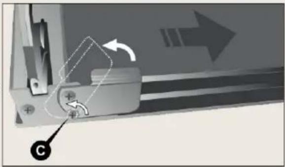
natural_image
Mechanical assembly diagram showing a bracket with arrows indicating motion and a labeled point C (no text or symbols present)To clean the area between the outer glass and the intermediate glass, use a soft brush in the space between the glass panels, as shown on page 62. To refit the door, follow the instructions on page 62 in reverse order. When the hinges B are back in their seats, open the door all the way and re-fit the safety catches of the hinges, lowering the respective pins A (one for each hinge).
Warning:
After re-fitting the door, always be sure to re-fit the hinge safety catches.
10.2 Removing the oven door
The rack-holder frames can be removed to clean them separately and to facilitate cleaning the oven walls. The frames are hooked to the oven wall in the three points indicated by the arrows in the figure (detail 1).
* Press downward with your fingers as shown in detail 2 of the figure to release the frame from the upper pin.
* Lift the frame upward and take it out.
To re-fit proceed in the inverse direction. Set the lower part of the frame on the respective pins and press the upper part against the oven wall until it hooks onto the pin.
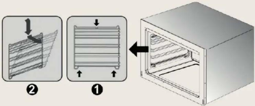
text_image
Diagram illustrating a cooling rack setup with labeled components and directional arrows indicating movement.10.3 Removing the oven door
The inside fan of the ventilated oven may require periodic cleaning. To disassemble the fan proceed as follows:
* Make sure that the power supply to the appliance is switched off.
* Remove all inside components (dripping pan, shelves).
* Loosen and remove the four screws A from the cover panel.
* Remove the cover panel B.
* Use a coin to loosen the fixing nut C of the fan (this threading is inverse; to loosen turn clockwise).
* Remove the fan D and wash it by immersing it in warm water and dish detergent. Never use abrasive or corrosive detergents, powdered products, or metal scrubbers. Rinse the fan and dry it thoroughly.
Re-fit the fan and the cover by working in the inverse direction to the instructions for removal.
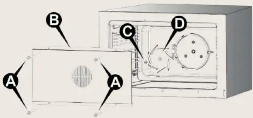
text_image
A B C D A10.4 Replacing the oven light bulb
Note:
Before carrying out maintenance, switch off the power supply to the appliance.
Proceed as follows:
* open the oven door;
* unscrew the glass safety cap anticlockwise;
* unscrew the bulb and replace it with another one for high temperatures (300°C) with the following characteristics:
* Refit the glass cap and switch on the power. It is possible to check that the oven light is working even when the door is closed by turning the function switch knob to position.
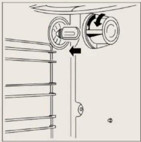
natural_image
Diagram of a mechanical device with rotating components and directional arrows, no text or symbols present
text_image
BORETTIPassione in Cucina


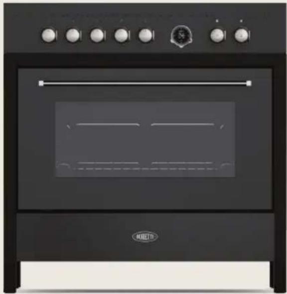
natural_image
Front view of a black double boiler oven with control knobs and a horizontal indicator (no visible text or symbols)HANDLEIDINGHANDLEIDING CRG916 / CRI915 CRG916 / CRI915
natural_image
Simple 3D illustration of a rectangular prism with no text or symbolsnatural_image
Three 3D geometric blocks in isometric view, no text or symbols presentnatural_image
Symbol of a trash bin crossed with no text or numbers, representing waste sorting or disposal (no text present)text_image
Diagram illustrating two 3D cube configurations labeled A and B, showing upward and downward motion with arrows and annotations.| AT | ● | |
| BE | ● | |
| CH | ● | |
| DE | ● | |
| DK | ● | |
| ES | ● | ● |
| FI | ● | ● |
| FR | ● | |
| GB | ● | |
| IE | ● | |
| IT | ● | ● |
| LU | ||
| NL | ● | |
| NO | ● | ● |
| PT | ● | ● |
| SE | ● | ● |
natural_image
Technical diagram of a mechanical assembly with three views (top, front, side) showing internal components and alignment indicators, labeled Fig. A (no text or symbols on the diagram itself)
natural_image
Illustration of a hand using a tool to press or install a mechanical component, labeled Fig. B (no text or symbols on the diagram itself)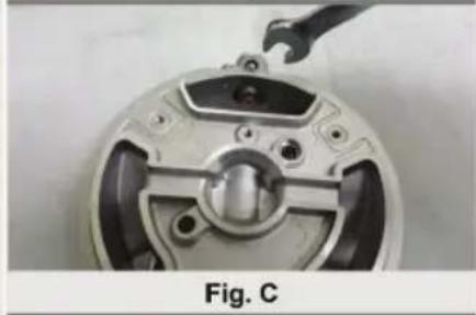
natural_image
Close-up of a mechanical component with a wrench inserted, labeled Fig. C (no text or symbols on the object itself)natural_image
Mechanical assembly diagram showing a circular component before and after assembly, with no visible text or symbols.text_image
Image showing a row of analog clocks with one clock displaying a magnified view, likely indicating time measurement or display.text_image
Diagram showing a row of circular gauges with labels 1 to 5 and a central gauge with '100' and '200' indicators.natural_image
Circular mechanical component with central double-headed arrow and eight small square buttons (no text or symbols)
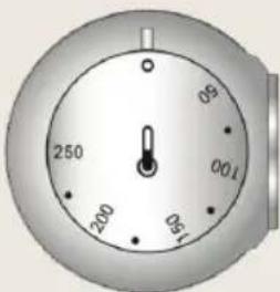
text_image
250 200 170 100 95natural_image
Six identical circular buttons with 'OFF' labels, arranged horizontally (no text or symbols on the buttons themselves)
natural_image
Two identical circular gauges with internal components, shown from different angles (no text or symbols visible)Grill-element: 1.950 W
7.3.2 Traditionele bereiding
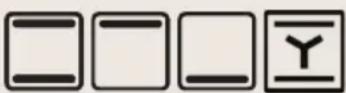
text_image
Diagram of a heating system with labeled components A, B, C, and D showing connections and a pressure gauge.natural_image
Line drawing of a cooking pot on a stove (no text or symbols)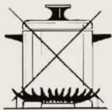
natural_image
Line drawing of a cooking pot with steam rising from a gridded base (no text or symbols)natural_image
Mechanical assembly diagram showing a sliding mechanism with motion arrows and a labeled component (no text or symbols)text_image
Diagram illustrating a mechanical assembly process with labeled steps ① and ②, showing structural changes in a container.natural_image
Diagram of a mechanical lifting mechanism with pulleys and rotating components (no text or labels)
text_image
BORETTIPassione in Cucina


natural_image
Exterior view of a black double boiler oven with control knobs and a 'MULTI' logo (no visible text or symbols on the appliance itself)MANUAL MANUAL
CRG916 / CRI915 CRG916 / CRI915
DE | BENUTZERHANDBUCH
www.boretti.com
Einführung
natural_image
Simple 3D illustration of a rectangular prism inside a transparent cube (no text or symbols)natural_image
Three 3D geometric blocks in wireframe and perspective views, no text or symbols presentnatural_image
Symbol of a trash bin crossed with no text or numbers, representing waste sorting or disposal (no text present)| AT | ● | |
| BE | ● | |
| CH | ● | |
| DE | ● | |
| DK | ● | |
| ES | ● | ● |
| FI | ● | ● |
| FR | ● | |
| GB | ● | |
| IE | ● | |
| IT | ● | ● |
| LU | ||
| NL | ● | |
| NO | ● | ● |
| PT | ● | ● |
| SE | ● | ● |
natural_image
Close-up of a mechanical component with a wrench and labeled Fig. C (no text or symbols on the object itself)natural_image
Diagram showing a mechanical component before and after assembly, with no visible text or symbolswerden.
natural_image
Row of circular gauges with a central dial and a dotted line above, no visible text or symbols on the gauges themselves.natural_image
Row of circular industrial gauges with a central display, no visible text or symbols on the gauges themselves.natural_image
Five identical circular mechanical components with mounting holes, arranged horizontally (no text or symbols visible)natural_image
Circular mechanical component with central cross and eight surrounding square slots (no text or symbols)
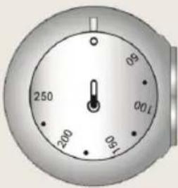
text_image
250 200 150 100 95 05 09natural_image
Two identical circular gauges with internal components and a central dial, shown from different angles (no text or symbols)Grillelement: 1.950 W
7.3.2 Traditionelles Garen
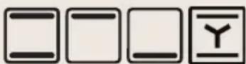
text_image
Diagram of a mechanical or electrical device with labeled components A, B, C, and D, showing connections and a directional arrow.natural_image
Line drawing of a cooking pot with a lid and side handles, placed on a portable stove (no text or symbols)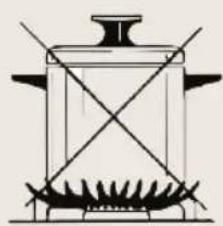
natural_image
Simple line drawing of a cooking pot with stirrer and pan (no text or symbols)natural_image
Diagram showing a circular object with an arrow and labeled point A, connected to a rectangular panel (no text or symbols present)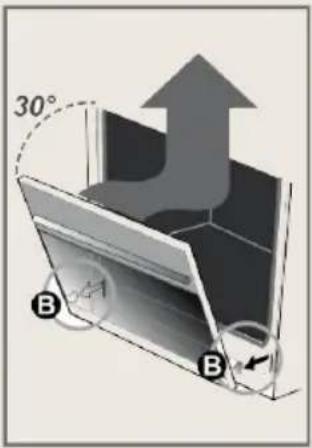
text_image
30° B B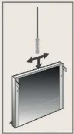
natural_image
Diagram of a device with a vertical rod and directional arrows indicating motion or force (no text or symbols)natural_image
Mechanical assembly diagram showing a bracket with mounting holes and directional arrows indicating motion (no text or symbols)text_image
Diagram illustrating two steps of a heating or cooling system: (1) heat transfer from a grid to a heater, (2) cooling with heat flow arrows.natural_image
Diagram of a mechanical device with rotating components and directional arrows, no text or symbols presentnatural_image
Exterior view of a black double boiler oven with control knobs and a 'MULTI' logo (no text or symbols on the appliance itself)MANUELMANUEL
CRG916 / CRI915 CRG916 / CRI915
FR | NOTICE D'UTILISATION
www.boretti.com
Introduction
natural_image
Simple 3D illustration of a rectangular prism inside a transparent cube (no text or symbols)natural_image
Three 3D rectangular blocks arranged in a staggered layout (no text or symbols)1.1 Service technique
natural_image
Symbol of a trash bin crossed with no text or numbers, representing waste sorting or disposal (no text present)| AT | ● | |
| BE | ● | |
| CH | ● | |
| DE | ● | |
| DK | ● | |
| ES | ● | ● |
| FI | ● | ● |
| FR | ● | |
| GB | ● | |
| IE | ● | |
| IT | ● | ● |
| LU | ||
| NL | ● | |
| NO | ● | ● |
| PT | ● | ● |
| SE | ● | ● |
natural_image
Technical diagram of a mechanical assembly with three views (top, front, side) showing internal components and alignment indicators, labeled Fig. A (no text or symbols on the diagram itself)
natural_image
Line drawing of a hand using a tool to adjust or install a mechanical component, labeled Fig. B (no text or symbols on the diagram itself)
natural_image
Close-up of a mechanical component with a wrench inserted, labeled Fig. C (no text or symbols on the object itself)natural_image
Diagram showing a mechanical component before and after assembly, with no visible text or symbolstext_image
Diagram showing a series of circular gauges with labels 1 through 9 and a central gauge with icons, aligned with a dotted line.natural_image
Row of grayscale analog clocks with a central display showing 12 o'clock (no text or symbols on the clock faces)natural_image
Five identical circular gauges with control knob, arranged horizontally (no text or symbols visible)natural_image
Circular mechanical component with central cross and eight surrounding square slots (no text or symbols)
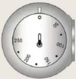
text_image
250 200 150 100 90natural_image
Two identical circular gauges with internal symbols, one showing a segmented design and the other displaying a dial (no text or labels visible)text_image
Diagram of a refrigerator interior with labeled parts A, B, C, and D showing internal components and wiring connections.7.3.7 Décongélation
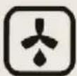
natural_image
Line drawing of a cooking pot on a stove (no text or symbols)
natural_image
Line drawing of a cooking pot with stirrer and pan (no text or symbols)natural_image
Diagram showing a circular object with an arrow and labeled point A, connected to a layered structure with arrows indicating direction (no text or symbols present)
text_image
30° B B