BNK601AN - Cooker BORETTI - Free user manual and instructions
Find the device manual for free BNK601AN BORETTI in PDF.
| Brand | Boretti |
| Model | BNK601AN |
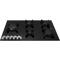
| Appliance type | Built-in gas cooker |
| Dimensions (W x D) | 560 x 480 mm |
| Approximate weight | 12 kg |
| Power supply | 230 V ~ 50 Hz |
| Gas type | G20 (natural gas) or G30 (butane/propane) depending on setting |
| Number of burners | 4 |
| Auxiliary burner | 1 000 W (Ø 10-14 cm) |
| Semi-rapid burner | 1 750 W (Ø 16-18 cm) |
| Rapid burner | 3 000 W (Ø 20-22 cm) |
| Triple ring burner | 3 500 W (Ø 22-24 cm) |
| Ignition | Automatic with safety valve |
| Controls | 4 rotary knobs |
| Safety | Safety valve that cuts off gas if the flame goes out |
| Surface material | Stainless steel and enamel |
| Grates | Dishwasher safe |
| Burner maintenance | Clean with soapy water, check the flame channels |
| Electrical connection | Cable H05VV-F 3x0.75 mm² without plug |
| Gas connection | Cylindrical or conical connection, rigid tube or flexible steel |
| Appliance class | Class 3 |
Frequently Asked Questions - BNK601AN BORETTI
User questions about BNK601AN BORETTI
0 question about this device. Answer the ones you know or ask your own.
Ask a new question about this device
Download the instructions for your Cooker in PDF format for free! Find your manual BNK601AN - BORETTI and take your electronic device back in hand. On this page are published all the documents necessary for the use of your device. BNK601AN by BORETTI.
USER MANUAL BNK601AN BORETTI
ALGEMENE WAARSCHUWINGEN
ALGEMENE WAARSCHUWINGEN
ALGEMENE WAARSCHUWINGEN
BELANGRIJKE WAARSCHUWING
DE HIERNA VERMELDE HANDELINGEN MOETEN UITGEVOERD WORDEN VOLGENS DE VAN KRacht ZIJNDE NORMEN, UITSLUITEND DOOR GESCHOOLD PERSONEEL. DE FABRIKANT WIJST ALLE VERANTWOORDELijkHEID AF VOOR SCHADE AAN MENSEN, DIEREN OF ZAKEN DIE HET GEVOLG IS VAN DE NIETNALEVING VAN DEZE BEPALINGEN
INSTALLATIE
We thank you and congratulate you on granting us your preference, by purchasing one of our products. We are sure that this new appliance, manufactured with quality materials, will meet your requirements in the best possible way.
The use of this new equipment is easy. However, we invite you to read this booklet carefully, before installing and using the appliance. This booklet gives the right information on the installation, use and maintenance, as well as useful advice.
THE MANUFACTURER
GB
GENERAL NOTICE
Declaration of conformity:
CE It declares that our products comply with current European directives, orders and regulations, and the requirements stated in the reference standards.
WARNING:
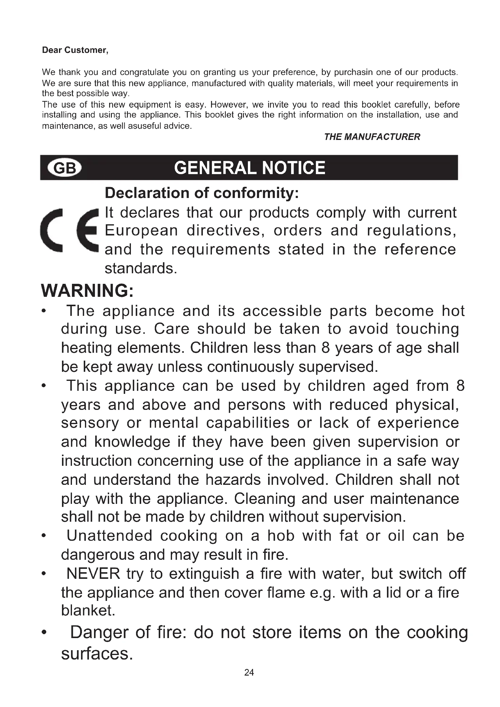
- The appliance and its accessible parts become hot during use. Care should be taken to avoid touching heating elements. Children less than 8 years of age shall be kept away unless continuously supervised.
- This appliance can be used by children aged from 8 years and above and persons with reduced physical, sensory or mental capabilities or lack of experience and knowledge if they have been given supervision or instruction concerning use of the appliance in a safe way and understand the hazards involved. Children shall not play with the appliance. Cleaning and user maintenance shall not be made by children without supervision.
- Unattended cooking on a hob with fat or oil can be dangerous and may result in fire.
- NEVER try to extinguish a fire with water, but switch off the appliance and then cover flame e.g. with a lid or a fire blanket.
- Danger of fire: do not store items on the cooking surfaces.
GENERAL NOTICE
- Don't use a steam cleaner for the cleaning the hob.
- The appliance is not intended to be operated by means of an external timer or separate remote-control system.
- Do not use the hob during cleaning
- These instructions apply only if the symbol of the country appears on the appliance. If the symbol not appear on the device you need to refer to the technical instructions required that the manufacturer will provide for the amendment of the appliance in terms of use of the destination country.
- Carefully read the instructions before installing and using the appliance. The manufacturer is not responsible if the installation and improper use of the device causing injury or damage. Keep the instructions handy as a reference for the future.
- Never leave the appliance unattended during food preparation because oil and grease could cause a fire.
- When the unit is connected directly to the power supply, you need a switch insulating omnipolar. It is necessary that the appliance can be completely disconnected from the network in accordance with the conditions of the category III on the overvoltage
GENERAL NOTICE
The earth cable is not included.
- If the power cable is damaged, it must be replaced by the manufacturer, by an authorized technician or by a qualified person to avoid danger.
- When connecting the power cable, make sure it is not in direct contact (eg. through the use of insulation sleeves) with parts that can reach temperatures of over 50^ .
- For any operations or modifications, contact an authorized technical assistance center and request original spare parts.
The product label, with the serial number, is sticked under the hob.
We invite you to read this instruction booklet carefully, before installing and using the equipment. It is very important that you keep this booklet together with the equipment for any future consultation. If this equipment should be sold or transferred to another person, make sure that the new user receives the booklet, so that he can learn how to operate the appliance and read the corresponding notice. This is a Class 3 appliance.
INSTRUCTIONS FOR THE USER

It is necessary that all the operations regarding the installation, adjustment and adaptation to the type of gas available are carried out by qualified personnel, in conformity with the regulations in force.
The specific instructions are described in the booklet section intended for the installer.
USING THE BURNERS
The symbols silk-screen printed on the side of the knob indicate the correspondence between the knob and the burner.
Automatic start-up with valves
Turn the corresponding knob anticlockwise up to the maximum position (large flame, fig.1) and press the knob.
Once the burner has been started up, keep the knob pressed for about 10 seconds.
Using the burners
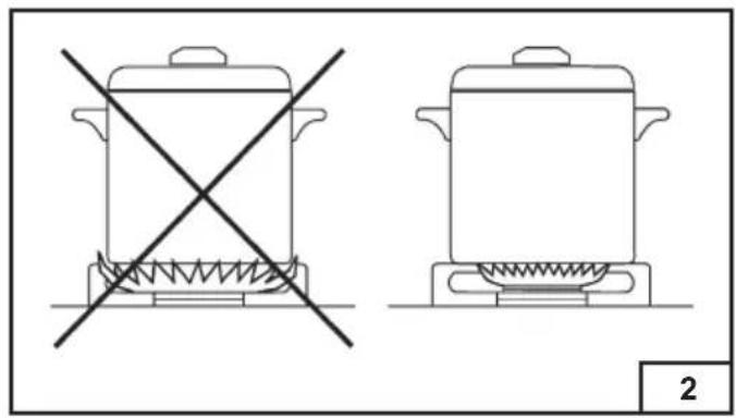
In order to obtain the maximum yield without waste of gas, it is important that the diameter of the pot is suitable for the burner potential (see the following table), so as to avoid that the flame goes out of the pot bottom (fig. 2).
Use the maximum capacity to quickly make the liquids reach the boiling temperature, and the reduced capacity to heat food or maintain boiling. All of the operating positions must be chosen between the maximum and the minimum ones, never between the minimum position and the closing point.
The gas supply can be interrupted by turning the knob clockwise up to the closing position.
If there is no power supply, it is possible to light the burners with matches, setting the knob to the startup point (large flame, fig. 1).
| BURNERS Power W Ø of pots | ||
| Auxiliary 1000 1 | 0 - 14 cm | |
| Semi-rapid 1750 | 16 - 18 cm | |
| Rapid 3000 20 - | 22 cm | |
| Triple crown 3500 | 22 - 24 cm | |
Notice
- When the equipment is not working, always check that the knobs are in the closing position (see fig.1).
- If the flame should blow out accidentally, the safety valve will automatically stop the gas supply, after a few seconds. To restore operation, set the knob to the lighting point (large flame, fig. 1) and press.
- While cooking with fat or oil, pay the utmost attention as these substances can catch fire when overheated.
- Do not use sprays near the appliance in operation.
- Do not place unstable or deformed pots on the burner, so as to prevent them from overturning or overflowing.
- Make sure that pot handles are placed properly.
- When the burner is started up, check that the flameis regular and, before taking pots away, always lowerthe flame or put it out.
CLEANING
Before any operation, disconnect the appliance from the electric grid. Don't use a steam cleaner for the cleaning the hob. It is advisable to clean the appliance when it is cold.
Enamelled parts
The enamelled parts must be washed with a sponge and soapy water or with a light detergent.
Do not use abrasive or corrosive products.
Do not leave substances, such as lemon or tomato juice, salt water, vinegar, coffee and milk on the enamelled surfaces for a long time.
INSTRUCTIONS FOR THE USER
CLEANING
Stainless steel parts
Stainless steel can be stained if it remains in contact with highly calcareous water or aggressive detergents for an extended period of time.
The stainless steel parts should also be cleaned with soapy water and then dried with a soft cloth.
Burners and racks
These parts can be removed to make cleaning easier.
The burners must be washed with a sponge and soapy water or with a light detergent, wiped well and placed in their housing perfectly.
Make sure that the flame-dividing ducts are clogged.
Check that the feeler of the safety valve and the start-up electrode are always perfectly cleaned, so as to ensure an optimum operation.
Gas taps
The possible lubrication of the taps must be carried out by specialized personnel, exclusively.
In case of hardening or malfunctions in the gas taps, apply to the Customer Service.
INSTRUCTIONS FOR THE INSTALLER

IMPORTANT NOTICE:
THE OPERATIONS INDICATED BELOW MUST BE FOLLOWED BY QUALIFIED PERSONNEL EXCLUSIVELY, IN CONFORMITY WITH THE REGULATIONS IN FORCE.
THE MANUFACTURING FIRM REFUSES ALL RESPONSIBILITY FOR DAMAGES TO PEOPLE, ANIMALS OR THINGS, RESULTING FROM THE FAILURE TO COMPLY WITH SUCH PROVISIONS.
INSTALLATION
The installation must be performed in conformity with current regulations.
Installing the top
The appliance is designed to be embedded into heat-resistant pieces of furniture.
The walls of the pieces of furniture must resist a temperature of 75^ besides the room one.
The equipment must not be installed near inflammable materials, such as curtains,cloths,etc. Make a hole in the top of the piece of furniture, with the dimensions indicated in fig. 3, keeping a distance of at least 50~mm between the rear edge of the installed device and 100~mm from the adjacent side walls.
| MODEL L (mm) D (mm) | ||
| BKW601 BNK601AN | 560 480 | |
| BKW751 BNK751AN | 560 480 | |
| BKW901 820 480 | ||
Any possible wall unit over the cook-top must be placed at a distance of at least 760~mm from the top.
It is advisable to isolate the appliance from the piece of furniture below with a separator, leaving a depression space of at least 10mm (fig. 4).
If the hob is going to be installed on the top of an oven, precautions must be taken to guarantee an installation in accordance with current accident prevention standards. Pay particular attention to the position of the electric cable and gas pipe: they must not touch any hot parts of the oven.
Moreover, if the hob is going to be installed on the top of a built in oven without forced cooling ventilation, proper air vents must be installed to guarantee an adequate ventilation, with the lower air entering with a cross section of at least 200cm^2 and the higher air exiting with a cross section of at least 60cm^2 .
INSTRUCTIONS FOR THE INSTALLER
Fastening the top
Every cook-top is equipped with a special washer.
A set of hooks is also supplied for mounting the cook-top.
Depending on the type of mounting surface, the suitable type of mounting hook is supplied (hook A or hook B).
For the installation proceed as follows:
- Remove the racks and burners from the top.
- Turn the appliance upside down and lay the washer S along the external border (fig. 5).
- Introduce and place the cook-top in the hole made in the piece of furniture, then block it with the V screws of the fastening hooks G (fig.6 / 6A).
Installation room
This appliance is not provided with a device for exhausting the products of combustion.
Regarding room ventilation rules where appliance is installed make reference to the legislation, in conformity with the local regulations.
The room where the appliance is installed must have a minimum volume of 20m^3
The influx of air must be through a permanent opening on the walls of the room and communicating with the outside.
Ventilation can also come from an adjoining room, in this case respect the standards in force on this subject.
The openings must have a minimum section of 200cm^2
ATTENTION:
The electrical connection of the cooking hob and the oven must be carried out separately for security issues and to allow easy removal of the oven from the unit
FOR THE U.K. ONLY
The room containing this hotplate should have an air supply in accordance with BS 5440: Part 2: 1989.
- All rooms require an openable window, or equivalent and some rooms will require a permanent vent a well.
- For room volumes up to 5m^3 an air vent of 100cm^2 is required.
- For room volumes between 5m^3 and 10m^3 an air vent of 50cm^2 is required.
- If the room is greater than 5m and has a door that opens directly to the outside, then no air vent is required.
If there are other fuel burning appliances in the same room BS 5440: Part 2:1989 should be
consulted to determine the air vent requirements.
Gas connection
Choose fixed connections or use a flexible pipe in stainless steel in compliance with the regulation in force. If you use flexible metallic pipes, be careful they do not come in touch with mobile parts or they are not squeezed. Also be careful when the hob is put together with an oven.
ATTENTION: Make sure that the gas supply pressure of the appliance obeys the recommended values
If the supplied pressure has not the specified value, it is necessary to assemble a proper pressure regulator in compliance with the standard UNI EN 88.
For Liquid Gas (LPG) the use of pressure regulator is allowed only if they are in compliance with UNI EN 12864. The adjustable connection is the comprehensive ramp by means of a threaded nut G 1/2" . Screw the parts without force, adjust the connection inthe necessary direction and tighten everything (fig.7).
Rigid connection:arry out connection by using metal rigid pipes (copper with mechanical end) (UNI-CIG 7129).
Flexible connection: Use a flexible pipe in stainless steel (UNI-CIG 9891) with a maximum length 2m .
When installation is complete, make sure that the seal of each pipe fittingis correct.
Use a soapy solution, not a flame
Electric connection
The connection to the electric grid must be carried out by qualified personnel and in conformity with the regulations in force.
The voltage of the electric system must correspond to the value indicated in the label under the appliance. Make sure that the electric system is provided with an effective ground connection in compliance with the regulations and provisions of the law.
Grounding is compulsory.
INSTRUCTIONS FOR THE INSTALLER
GAS TRANSFORMATIONS AND ADJUSTMENTS
Replacing the nozzles
If the equipment is adjusted for a type of gas that is different from the one available, it is necessary to replace the burner nozzles.
The choice of the nozzles to replace must be made according to the table of the "technical characteristics" as enclosed.
Act as follows:
- Remove the racks and burners.
- By means of a straight spanner L, unscrew the nozzle U (fig.8) and substitute it with the corresponding one.
- Tighten the nozzle strongly.
Adjusting the burners
The lowest flame point must always be properly adjusted and the flame must remain on even if there is an abrupt shift from the maximum to the minimum position.
If this is not so, it is necessary to adjust the lowest flame point as follows:
- start the burner up
- turn the tap up to the minimum position (small flame)
- remove the knob from the tap rod
- introduce a flat-tip screwdriver in the hole F of the tap (fig.9-9/A) and turn the by-pass screw up to a proper adjustment of the lowest flame point.
As regards G30 gas burners, the by-pass screw must be tightened completely.
MAINTENANCE
Replacing the power supply cable
If the power supply cable should be replaced, it is necessary to use a cable with a section of 3 × 0.75 ~mm^2 type H05V2V2-F or H05RR-F for models all gas or 3 × 1.5 ~mm^2 type H05V2V2-F or H05RR-F for models mixed, complying with the regulations in force.
The connection to the terminal board must be effected as shown in fig. 10-10/A:
brown cable L (phase)
blue cable N (neutral)
green-yellow cable (ground)
If the supply cord is damaged, it must be replaced by the manufacturer, its service agent or similarly qualified persons in order to avoid a hazard.
The manufacturing firm refuses all responsibility for any possible imprecision in this booklet, due to misprints or clerical errors. It reserves the right to make all the changes that it will consider necessary in its own products, without effecting the essential characteristics of functionality and safety.
BKW601 / BNK601AN

BKW751 / BNK751AN

BKW901
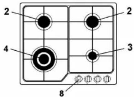
1 Rapid burner 3000 W
2 Semi-rapid burner 1750 W
3 Auxiliary burner 1000 W
4 Triple ring burner 3500 W
8 Control knob for burner
TECHNICAL CHARACTERISTIC TABLES
| BRULEURS BRENNER BRANDERS BURNERS | GAZ GAS GAS GAS | PRESSION DE SERVICE BETRIEBS-DRUCK DRUK BIJ WERKING NORMAL PRESSURE | DEBIT LEISTUNG VERBRUJK NORMAL RATE | DIAMÈTER INJECTOR DURCHEMS- SER DÜSEN DIAMETER INJECTOR INJECTOR DIAMETER | DIAMÈTER BY PASS ROBINET DUR-CHEMSSER UM- LEITVENTIL DIAMETER BYPASS KRAAN TAPE BY PASS DIAMETER | DEBIT CALORIFIQUES (W) WÜRMELEI-STUNG (W) WARMTEVERMO- DEN (W) NOMINAL HEAT INPUT (W) | |||
| h/1/100 mm 1/100 mm Max. Min. | |||||||||
| N° | DESIGNATION BESCHREIBUNG NAAM DESCRIPTIONS | mbar g/h L | |||||||
| 1 | RAPIDE SCHNELL-BRENNER SNEL RAPID | G30-G31 30 G25.3 25 | 225 - 85 42 332 121 REG. 3000 | 3000 950 950 | |||||
| 2 | SEMI-RAPIDE MITTLERER BRENNNER HALF-SNEL SEMI-RAPID | G30-G31 30 G25.3 25 | 126 - 65 31 194 94 | 1750 600 REG. 1750 600 | |||||
| 3 | AUXILIAIRE HILFSBRENNER HULP AUXILIARY | G30-G31 30 G25.3 | 71 25 | - 50 27 100 111 | 0 450 72 | REG. | 1000 | 450 | |
| 4 | TRIPLE COURONNE DREIFACHER BRENNKRANZ TRIPLE KROON TRIPLE RING | G30-G31 28 G25.3 25 | 380 145 REG. 3500 | 8 65 38 00 2100 | 0 100 2100 | ||||
Short title or reference to the measurement and calculation methods used to establish compliance with the above requirements.
The performance of each individual burner is calculated according to standard EN 30-2-1 (2015)
The total efficiency of the hob is calculated according to the EU Regulation 66/2014 Par. 2.2
The efficiency is calculated only for the burners with a nominal capacity exceeding 1,16 KW ( EN 30-2-1 (2015))
Information which is relevant to the customer to minimize the energy consumption during usage:
Energy Saving Tips: use pots having flat base, Use pots with proper size, use pots with lid, minimize the amount of liquid or fat, when liquid starts boiling reduce the setting.


| Modèle d'identification / Identifikationsmodell / Identificatiemodel / Model identification | BKW601 / BNK601AN |
| Type de table de cuisson / Art des Kochfelds / Type kookplaat / Tye of hob | PLAQUE DE CUISSON RECESSSED / EINBAUKOCHPLATZ / INGEKOOKTE KOOKPLAAT / GAS BUILT IN HOB |
| Nombre de zones de cuisson / Anzahl der Kochzonen / Aantal kookzones / Number of cooking zones | 4 |
| Technique de chauffage / Heiztechnik / Verwarmingstechnologie / Heating technology | GAZ / GAS / GAS |
| Brûleur de position / Brenner positionieren / Positie brander / Position Burner | Type brûleur / Typ Brenner / Typ de brander / Type burner | Efficacité énergétique du brûleur à gaz / Energieeffizienz für Gasbrenner / Energie-efficiente pour gasbrander / Energy efficiency for gas burner | ||
| Avant Gauche / Links Vorne / Links Vooraan / Front Left | TRIPLE COURONNE DREIFACHER BRENNKRANZ TRIPLE KROON TRIPLE CROWN | EE gas burner 52,5 % | ||
| Arrière Gauche / Hinten links / Linksachter / Rear Left | SEMI-RAPIDE / MITTLERER BRENNER / HALF-SNEL / SEMI-RAPID | EE gas burner 57,0 % | ||
| Arrière Droite / Hinten rechts / Rechtsachter / Rear Right | SEMI-RAPIDE / MITTLERER BRENNER / HALF-SNEL / SEMI-RAPID | EE gas burner 57,0 % | ||
| Avant Droite / Vorne rechts / Rechtsvoir / Front Right | AUXILIAIRE / HILFSBRENNER HULP / AUXILIARY | EE gas burner ** % | ||
| Efficacité énergétique pour la table de cuisson à gaz / Energieeffizienz für das Gaskochfeld / Energie-efficiente voor de gaskookplaat Energy efficiency for the gas hob | EE gas hob 55,5 % | |||
| Modèle d'identification / Identifikationsmodell / Identificatiemodel / Model identification | BKW751 / BNK751AN / BKW901 |
| Type de table de cuisson / Art des Kochfelds / Type kookplaat / Tye of hob | PLAQUE DE CUISSON RECESSSED / EINBAUKOCHPLATZ / INGEKOOKTE KOOKPLAAT / GAS BUILT IN HOB |
| Nombre de zones de cuisson / Anzahl der Kochzonen / Aantal kookzones / Number of cooking zones | 5 |
| Technique de chauffage / Heiztechnik / Verwarmingstechnologie / Heating technology | GAZ / GAS / GAS |
| Brûleur de position / Brenner positionieren / Positie brander / Position Burner | Type brûleur / Typ Brenner / Typ de brander / Type burner | Efficacité énergétique du brûleur à gaz / Energieeffizienz für Gasbrenner / Energie-efficiente pour gasbrander / Energy efficiency for gas burner | ||
| Centre Gauche / Links Zentral / Links Centraal / Central Left | TRIPLE COURONNE DREIFACHER BRENNKRANZ TRIPLE KROON TRIPLE CROWN | EE gas burner 52 | 5 % | |
| Arrière Central / Zentrale Rückseite / Centrale achterkant / Central rear | SEMI-RAPIDE / MITTLERER BRENNER / HALF-SNEL / SEMI-RAPID | EE gas burner 57 | 0 % | |
| Avant central / Zentrale Front / Centrale voorkant / Central Front | AUXILIAIRE / HILFSBRENNER HULP / AUXILIARY | EE gas burner ** | % | |
| Arrière Droite / Hinten Rechts / Rechtsachter / Rear Right | RAPIDE / SCHNELL-BRENNER / SNEL / RAPID | EE gas burner 56 | 7 % | |
| Avant Droite / Vorne Rechts / Rechtsvoor / Front Right | SEMI-RAPIDE / MITTLERER BRENNER / HALF-SNEL / SEMI-RAPID | EE gas burner 57 | 0 % | |
| Efficacité énergétique pour la table de cuisson à gaz / Energieeffizienz für das Gaskochfeld / Energie-efficiente voor de gaskookplaat | EE gas hob 55,8 % | |||
The manufacturer declines all responsibility for any inaccuracies caused by printing or transcription errors in this manual. He reserves the right to make any changes to his products that he deems appropriate without affecting the essential operating and safety features.
| FR | Ce produit est conforme à la Directive EU 2012/19/UE. Cette note informative s'adresse exclusivement aux propriétaires d'appareils représenté le symbole de la figure A sur l'étiquette adhéensive montrant les données techniques appliquées sur le produit lui-même (étiquette matricielle): Ce symbole indique que le produit est classées selon la réglementation en vigueur, comme équipement électrique ou électronique et e Se conforme donc à la directive 2012/19 / UE (DEEE), à la fin de sa propre vie utile, doit être traités séparément des déchets menagers, le livrer gratuitemment à un point de collecte séparé pour l'équipement produits ELECTriques et Electroniques ou de le returner au concessionnaire lors de l'achat d'un nouvel apparil équivalent. L'utilisateur est responsable de l'attribution de l'équipment à la fin de la vie aux installations de collecte désignés, les sanctions prévues par la législation actuelle sur les déchets. Collecte appropriée pour l'envoi ultérieur de l'appareil pour le recyclage, le traitement et l'élimination écologiquement compatible permet d'éviter les effets négatifs possibles sur l'environnement et la santé humaine et favorise le recyclage des matériaux qui compose le produit. Pour plus d'informations sur les systèmes de collecte disponibles, contactez le service d'élimination des déchets local ou le magasin où l'achat a été effectué. Les fabricants et les importateurs se chargeant de leur recyclage, de leur traitement et de leur élimination respectieux de l'environnement, soit directement, soit en participant à un système collectif. |
| DE | Dieses Produkt ist konform mit der EG-Richtlinie 2012/19/UE. Dieser informative Hinweis richtig sich ausschließlich an Besitzer von Geräten, die Auf dem Klebeetikett das Symbol von Abb. A anzeigen, auf dem die technischen Daten angegeben sind auf dem Produkt selbst (Matrikelname): Dieses Symbol zeigt an, dass das Produkt ist klassifiziert nach den geltenden Vorschriften, als elektrische oder elektronische Geräte und e Erfüllt damit die Richtlinie 2012/19 / EU (WEEE) am Ende seiner selbst Nutzungsdauer, muss getrennt von Hausmüll behandelt werden, Lieferung kostenlos an einer separaten Sammelstelle für Geräte Elektro- und Elektronikgeräte oder beim Kauf eines neuen gleichwertigen Geräts an den Handler zurücksenden. Der Benutzer ist verantwortlich für das Gerät am Ende der Lebensdauer zu einer Sammelstelle Zuweisung vorgesehenen Sanctionen durch aktuelle Abfallgesetzgebung. Die angemessene, getrennte Sammlung für den nachfolgenden Versand des Gerätes zur Verwertung Behandlung und umweltgerechte Entsorgung hilft, mögliche negative Auswirkungen auf die Umwelt und die menschliche Gesundheit zu vermeiden und begünstigt das Recycling der Materialien, die das Produkt bilden. Wenden Sie sich für weitere Informationen zu den verfügbarbaren Sammelsystemen an den örtlichen Entsorgungs Dienst oder an das Geschäft, in dem der Kauf getätigtemurd. Hersteller und Importeurkommen ihrer Verantwortung für eine umweltgerechte Verwertung, Behandlung und Entsorgung entweder direkt oder durch Teilnahme an einem kollektiven System nach. |
| NL | Dit product is in overeenstemming met de EU-richtlijn 2012/19/UE. Deze informatieve notatie is uitsluitend gericht aan eigenaars van apparaten die presenterer het symbool van figuur A op het etiket met de toegepaste technische gegevens op het product zelf (matriculair label): dit symbool geeft aan dat het product het is geclassifieerd volgens de huidige regelgeving, als elektrische of elektronische apparatuur en e Voldoet waar aan Richtlijn 2012/19 / EU (AEEA), aan het einde van+zijn eentje levensduur,要去en geschaden van huishoudelijk afval worden behandeld, Gratis afleveren op een apart verzamelpunt voor apparatuur elektrische en elektronische producten of returneren aan de dealer bij aankoop van een/New, gelijkwaardig apparaat. De gebruiker is verantwoordelijk voor het toewijzen van de apparatuur aan het einde van het lever bestemde verzamelplaatsen, de sancties die door de huidige wetgeving afval. Passende geschaden inzameling voor deaaropvolgende verzending van het apparaat voor de recycling, behandeling en milieuvriendelijk afvalverwerking draagt bij aan mogelijk negatieve effecten op het milieu en de volksgezondheid te voorkomen en bevordert het recycleren van de materialen die deel uitmaken van het product. Neem voor meer informatie over de beschikbare inzamelsystemen contact op met deplaatselijk afvalverwerkingsdienst of de winkel waar de aankoop is gedaan. De producenten en importeurs voldoen aan hun verantwoordelijkhcheid voor i recyclung, behandeling en milieuvriendelijk verwerking, hetzijrechtstreeks, hetzij door deel te nemen in een collectief system. |
| GB | Directive 2012/19 / EU (WEEE). This informative note is addressed exclusively to owners of devices that present the symbol of Fig. A in the adhesive label showing the technical data applied on the product itself (matricularelabel): This symbol indicates that the product is classified according to current regulations, as electrical or electronic equipment and e Complies with Directive 2012/19 / EU (WEEE) therefore, at the end of its own useful life, must be treated separately from household waste, delivering it for free at a separate collection point for equipment electrical and electronic products or returning it to the dealer when buying a new equivalent device. The user is responsible for placing the appliance at the end of its life at the appropriate collection facilities, under penalty of the penalties provided for by the current waste legislation. Appropriate separate waste collection for the subsequent start-up of the disposed appliance to recycling, treatment and environmentally compatible disposal helps to avoid possible negative effects on the environment and on health and favors the recycling of the materials of which the product is composed. For more detailed information regarding the collection systems available, contact the local waste disposal service, or the store where the purchase was made. Manufacturers and importers comply with their responsibility for environmentally compatible recycling treatment and disposal either directly or by participating in a collective scheme.. |

Passione in Cucina