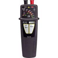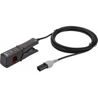
MINI 94 - Measuring equipment CHAUVIN ARNOUX - Free user manual and instructions
Find the device manual for free MINI 94 CHAUVIN ARNOUX in PDF.


User questions about MINI 94 CHAUVIN ARNOUX
0 question about this device. Answer the ones you know or ask your own.
Ask a new question about this device
Download the instructions for your Measuring equipment in PDF format for free! Find your manual MINI 94 - CHAUVIN ARNOUX and take your electronic device back in hand. On this page are published all the documents necessary for the use of your device. MINI 94 by CHAUVIN ARNOUX.
USER MANUAL MINI 94 CHAUVIN ARNOUX
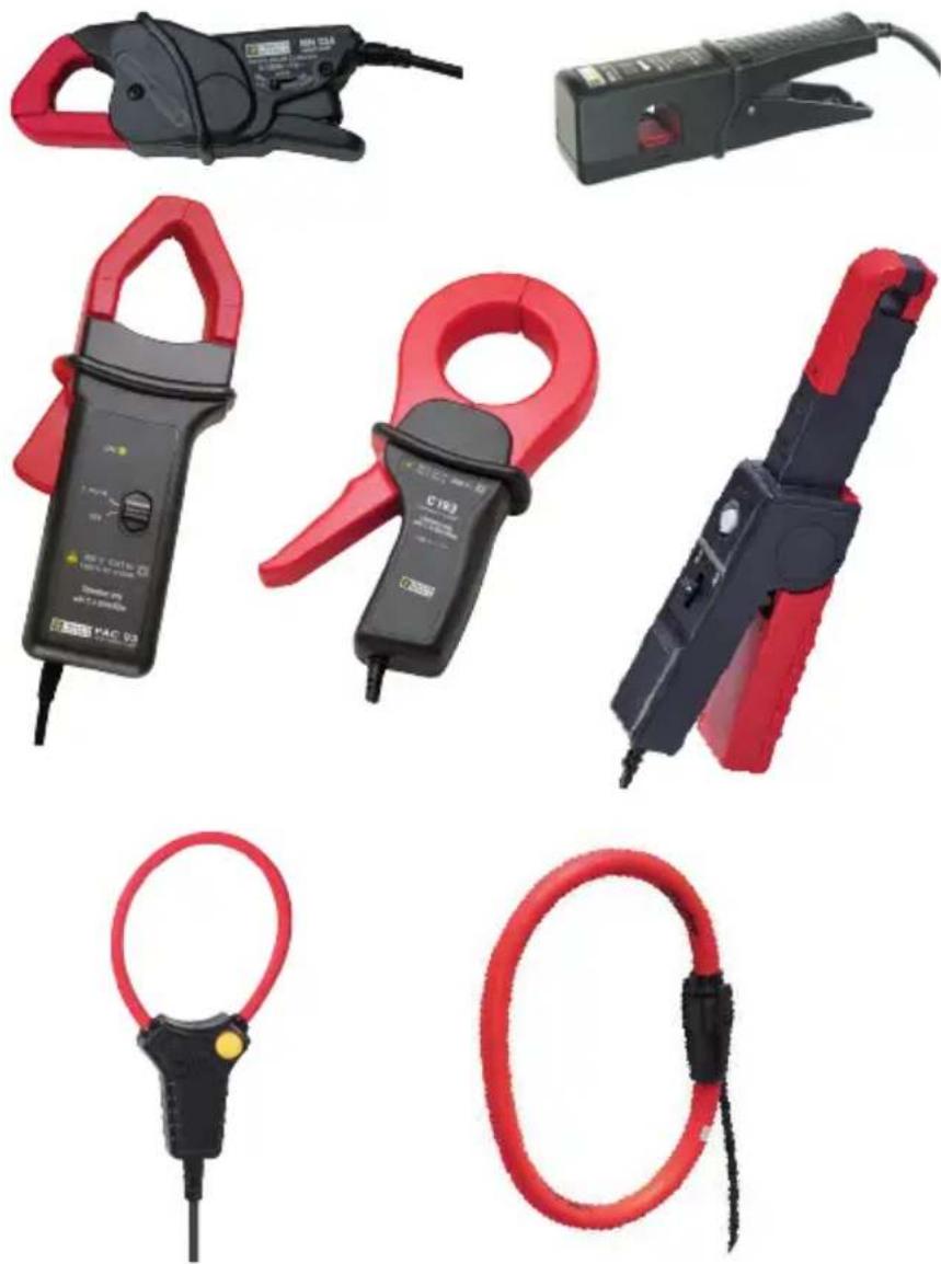
MN93, MN93A, MINI 94
PAC93, C193, E94
MiniFlex® MA193, MA194, MA196
AmpFlex® A193, A196A
Capteurs de courant
Current sensors
Stromwandler
Sensori di corrente
text_image
Diagram showing a plunger, battery, and charging device with polarity indicatorstext_image
Diagram showing a hairpin connected to a plug with labeled parts and directional arrows indicating movement or force.Pour les MiniFlex :
text_image
Diagram illustrating a medical procedure with a hand pointing to a circular component before and after a curved tube, showing directional change.ou
text_image
Diagram showing a hand pointing to a device with a yellow circular mark, followed by a red arrow indicating transformation or change.natural_image
Diagram showing two configurations of a connector with red and black wiring, no text or symbols presentMiniFlex MA193 250 mm
MiniFlex MA194 250 mm
MiniFlex MA193 350 mm
MiniFlex MA194 1000 mm
text_image
Technical diagram of a plunger tool with labeled components and a screwdriver inserted into a socketThank you for purchasing a MN93, MN93A, C193, PAC93, E94 or MINI94 AC current clamp or a MiniFlex MA193, MA194 or MA196, AmpFlex® A193 or A196A flexible current sensor. This current sensor should only be used only with C.A 8XXX and PEL analysers. Not all sensors are suitable for all instruments. Contact our customer service to make your choice.
For best service from your current sensor:
■ read these operating instructions carefully,
■ comply with the precautions for use.

WARNING, risk of DANGER! The operator must refer to these instructions whenever this danger symbol appears.

Current sensor protected by double insulation.

Application or withdrawal authorized on bare conductors carrying dangerous voltages. Type A current sensor as per IEC 61010-2-032.

Must not be applied to or removed from bare conductors at dangerous voltages. Type B current sensor as per IEC 61010-2-032.

The arrow indicates the phase of the current.

Battery.

The product has been declared recyclable after analysis of its life cycle in accordance with the ISO 14040 standard.

The CE marking indicates compliance with the European Low Voltage Directive (2014/35/EU), Electromagnetic Compatibility Directive (2014/30/EU), and Restriction of Hazardous Substances Directive (RoHS, 2011/65/EU and 2015/863/EU).

The UKCA marking certifies that the product is compliant with the requirements that apply in the United Kingdom, in particular as regards Low-Voltage Safety, Electromagnetic Compatibility, and the Restriction of Hazardous Substances.
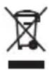
The rubbish bin with a line through it indicates that, in the European Union, the product must undergo selective disposal in compliance with Directive WEEE 2012/19/EU. This equipment must not be treated as household waste.
Definition of measurement categories
■ Measurement category IV corresponds to measurements taken at the source of low-voltage installations.
Example: power feeders, counters and protection devices.
■ Measurement category III corresponds to measurements on building installations. Example: distribution panel, circuit-breakers, machines or fixed industrial devices.
■ Measurement category II corresponds to measurements taken on circuits directly connected to low-voltage installations.
Example: power supply to electro-domestic devices and portable tools.
The protection assured by the current sensor can be compromised if it is used in a way that is not recommended by the manufacturer.
■ Comply with the rated maximum voltage and current and the measurement category. Do not use your current sensor on networks where the voltage or category exceeds those stipulated.
■ Comply with the conditions of use, that is to say temperature, humidity, altitude, degree of pollution and location of use.
■ Do not use the current sensor if its housing is open, deteriorated, or incorrectly reassembled. Before each use, check the integrity of the insulation of the core or of the arms of the clamps, of the housing, and of the leads.
■ Do not subject the current sensor to sprayed or falling water or other liquids.
■ Use suitable personal protective equipment when parts at hazardous voltages may be accessible in the installation where the measurement is made.
■ Any repairs must be carried out by accredited skilled personnel.
CONTENTS
1. PRESENTATION ...... 24
1.1. Clamps MN93 and MN93A....24
1.2. Clamp C193 25
1.3. Clamp PAC93.... 26
1.4.CLAMP E94....27
1.5.CLAMP MINI94 28
1.6. MiniFlex MA193.... 29
1.7. MiniFlex MA194.... 30
1.8. MiniFlex MA196.... 31
1.9.AmpFlex®A193....32
1.10.AmpFlex® A196A 33
1.11. Delivery condition 34
1.12. Accessories and spares 34
2. USE....35
3. CHARACTERISTICS ...... 38
3.1.Environmental conditions....38
3.2. Construction specifications .... 38
3.3. Conformity to international standards.... 39
4. MAINTENANCE....40
4.1. Cleaning....40
4.2. Replacing the battery of the PAC93 40
5. WARRANTY ....41
1.1. CLAMPS MN93 AND MN93A
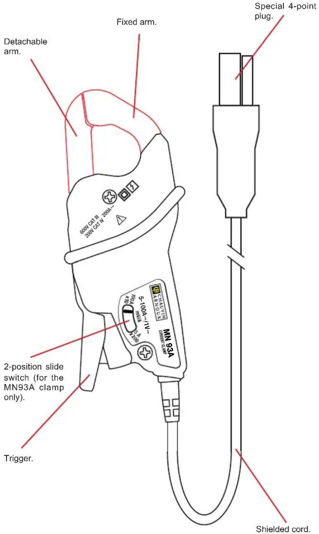
text_image
Detachable arm. 600V CAT III 200A 200V CAT IV 200A Fixed arm. Special 4-point plug. 2-position slide switch (for the MN93A clamp only). Trigger. MINER CLAMP 5-100A-/IV- mVA 4-100A CHAVIN ARNOUS MN 93A Trigger.1.2. CLAMP C193
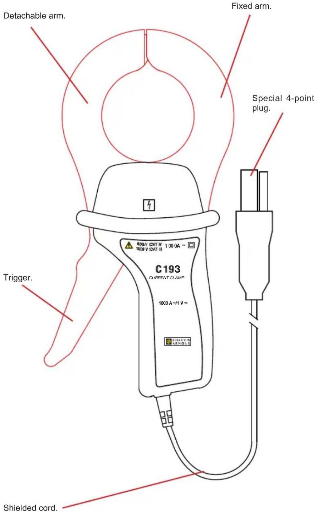
text_image
Detachable arm. Fixed arm. Special 4-point plug. Trigger. C193 CURRENT CLAMP 1000 A ~/1 V ~ CHAUVIN ABNOLX Shielded cord.1.3. CLAMP PAC93
Detachable arm. Fixed arm.
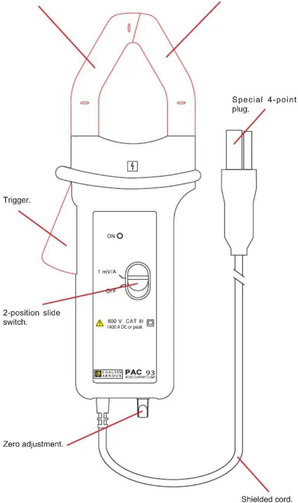
text_image
Trigger. 2-position slide switch. ON 1 mV/A OFF 600 V CAT III 1400 A DC or peak CHALVIN ARNDUX PAC 93 AC-DC CURRENT CLAMP Zero adjustment. Shielded cord. Special 4-point plug.1.4. CLAMP E94
Mobile jaw.
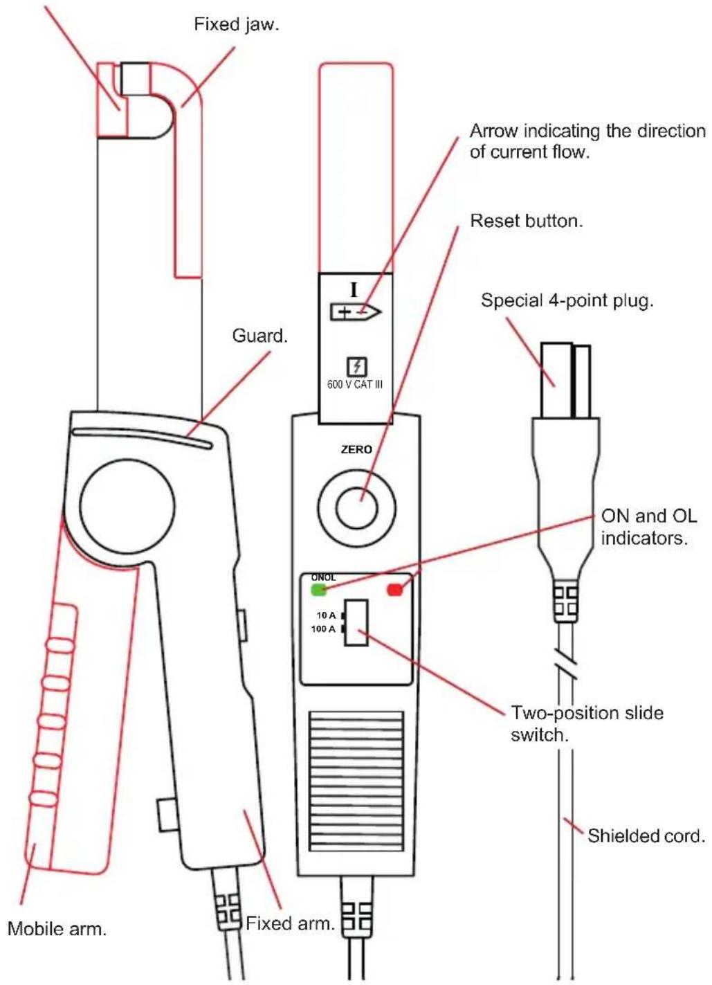
text_image
Fixed jaw. Guard. 600 V CAT III Arrow indicating the direction of current flow. Reset button. Special 4-point plug. ZERO ONOL 10 A 100 A ON and OL indicators. Two-position slide switch. Shielded cord. Mobile arm. Fixed arm.1.5. CLAMP MINI94
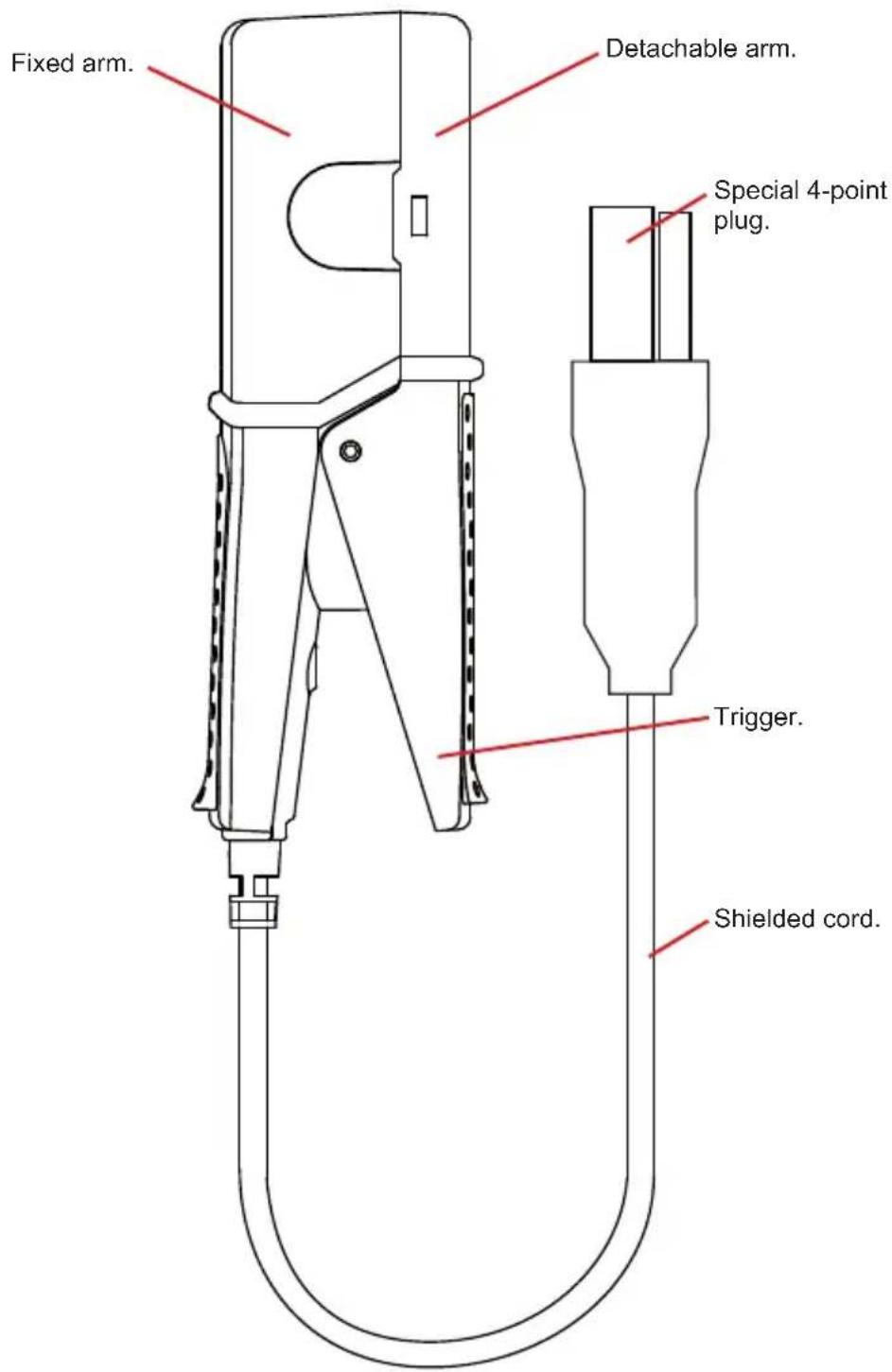
text_image
Fixed arm. Detachable arm. Special 4-point plug. Trigger. Shielded cord.1.6. MINIFLEX MA193
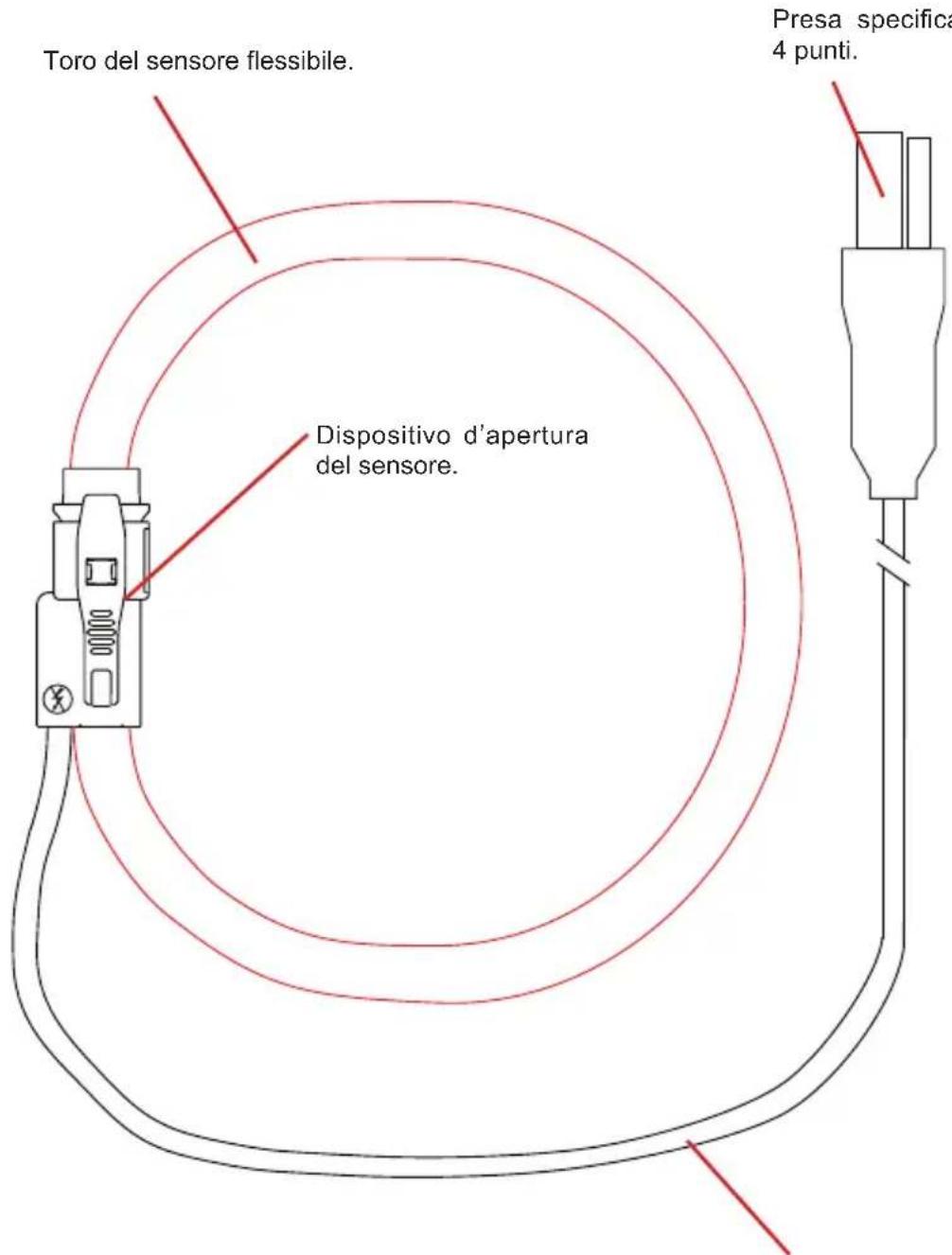
Core of the flexible sensor.
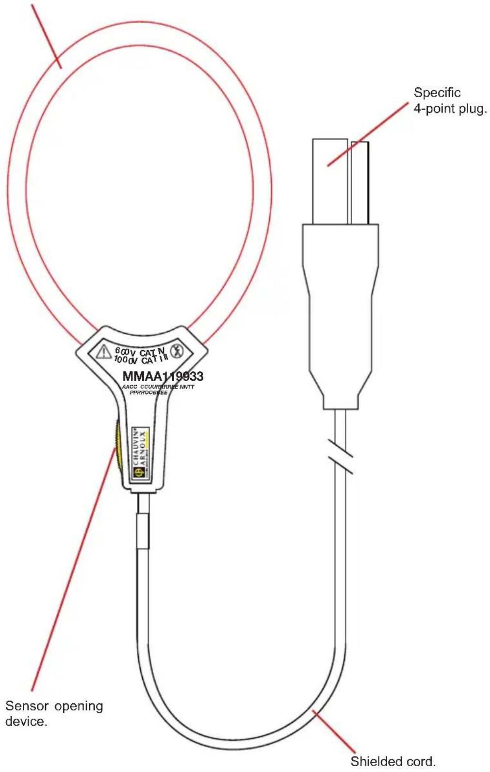
text_image
600V CAT N 7000V CAT 18 MMAA119933 AACC CCUURBREE NNIT PPRROODSEE CHAVIN ARMOLX Specific 4-point plug. Sensor opening device. Shielded cord.1.7. MINIFLEX MA194
Core of the flexible sensor.
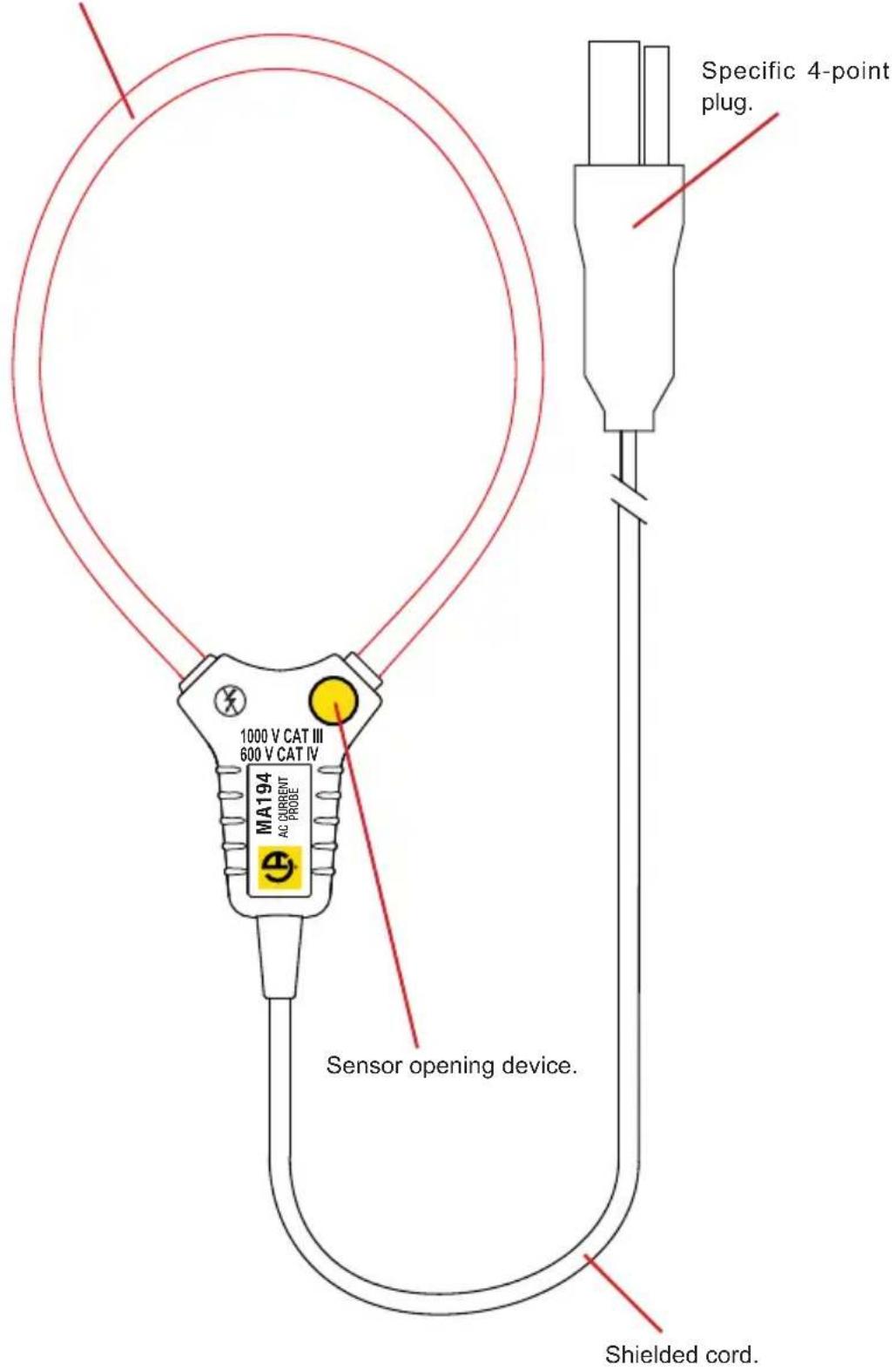
text_image
1000 V CAT III 600 V CAT IV MA194 AC CURRENT Sensor opening device. Shielded cord. Specific 4-point plug.1.8. MINIFLEX MA196
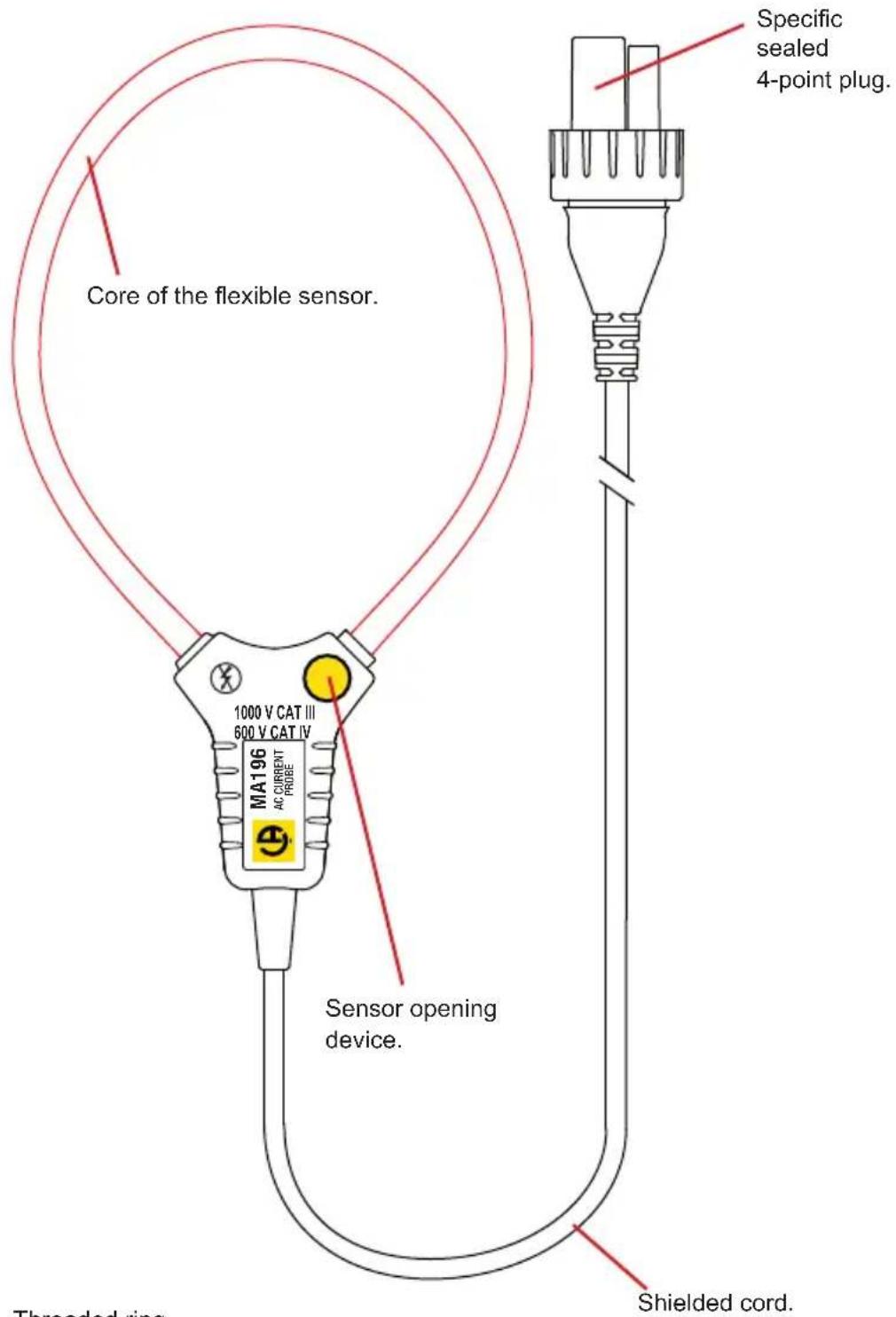
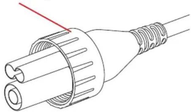
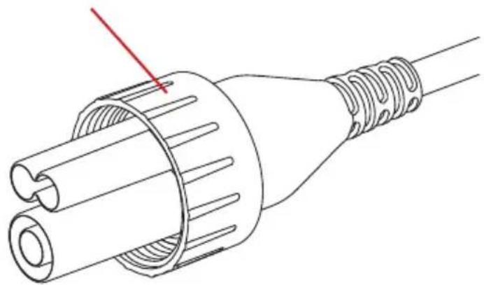
The connector on this sensor can be used to form a seal with the terminal to which it is connected, if the instrument has a threaded receptacle. Simply screw the ring on the connector onto the receptacle.
text_image
Core of the flexible sensor. 1000 V CAT III 600 V CAT IV MA196 AC CURRENT PROBE Sensor opening device. Shielded cord. Specific sealed 4-point plug. Threaded ring.Threaded ring.
natural_image
Technical line drawing of a mechanical connector with threaded end and internal structure (no text or symbols)1.9. AMPFLEX® A193
text_image
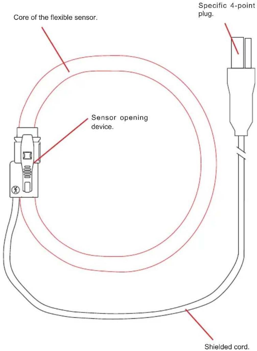
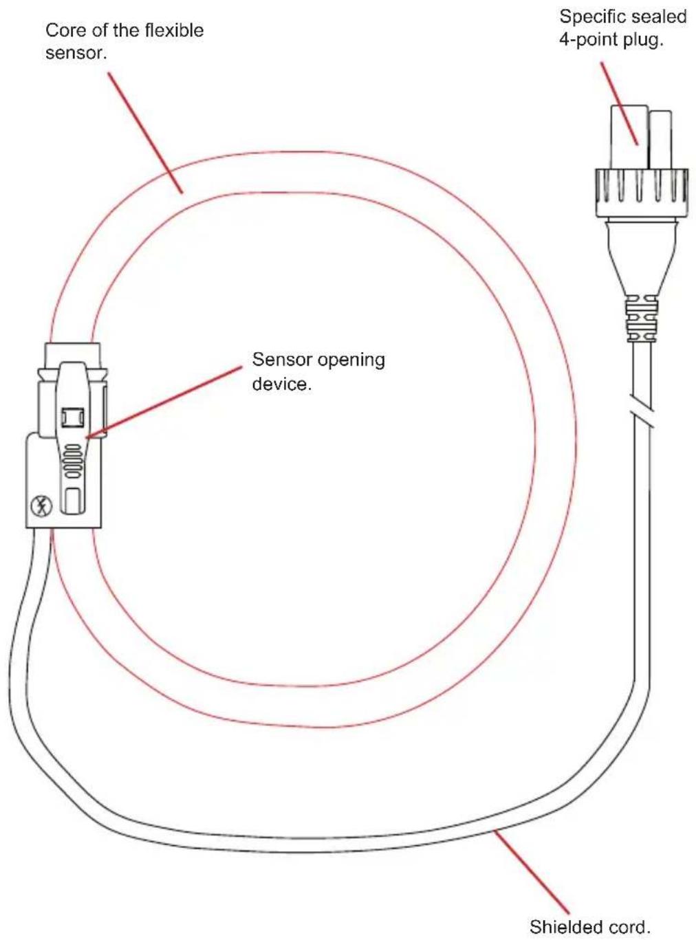
Core of the flexible sensor. Sensor opening device. Specific 4-point plug. Shielded cord.The connector on this sensor can be used to form a seal with the terminal to which it is connected, if the instrument has a threaded receptacle. Simply screw the ring on the connector onto the receptacle.
text_image
Core of the flexible sensor. Sensor opening device. Specific sealed 4-point plug. Shielded cord.Threaded ring.
natural_image
Technical line drawing of a mechanical connector with threaded end and internal ribs (no text or symbols)1.11. DELIVERY CONDITION
Clamp PAC93
Supplied in a cardboard box with:
■ a 9V battery,
■ a user manual in 5 languages,
■ a verification certificate.
Clamp MN93, clamp MN93A, clamp C193, clamp E94, clamp MINI94
Supplied in a cardboard box with:
■ a user manual in 5 languages,
■ a verification certificate.
MiniFlex MA193 250 mm sensor MiniFlex MA193 350 mm sensor MiniFlex MA194 250 mm sensor MiniFlex MA194 350 mm sensor MiniFlex MA194 1000 mm sensor MiniFlex MA196 350 mm sensor AmpFlex® A193 450 mm sensor AmpFlex® A193 800 mm sensor AmpFlex® A196A 610 mm sensor Supplied in a cardboard box with:
■ a user manual in 5 languages,
■ a verification certificate.
1.12. ACCESSORIES AND SPARES
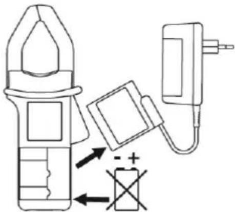
■ A main adapter for the PAC93.
text_image
Diagram showing a plunger, battery, and plug device with polarity indicators and circuit symbolsFor the accessories and spares, consult our web site: www.chauvin-arnoux.com
2. USE
Current clamps, MiniFlex and AmpFlex ^® flexible current sensors are used to measure the current flowing in a cable without opening the circuit. They also insulate the user from dangerous voltages in the circuit.
The choice of current sensor to be used depends on the current to be measured and the diameter of the cables.
| MN93 | MN93A5 A | MN93A100 A | |
| Measurement range * 0 | 05 - 240 A 0.005 - 6 | A 0.1 - 120 A | |
| Clamping diameter 20 mm | 20 mm 20 mm |
| C193 PAC93 | ||
| Measurement range * 1 | - 1.200 A 1 - 1.200 A | |
| Clamping diameter 52 mm | 39 mm |
| E9410 A | E94100 A | MINI94 | |
| Measurement range * 0 | 1 - 10 Apeak 0,5 - | 100 Apeak 0,05 - 200 A | |
| Clamping diameter 11,8 | mm | 16 mm |
| MiniFlexMA193250 mm | MiniFlexMA193350 mm | MiniFlexMA196350 mm | |
| Measurement range * | 100 mA - 10 000 A | 100 mA - 10 000 A | 100 mA - 10 000 A |
| Clamping diameter 70 mm | 100 mm 100 mm | ||
| MiniFlexMA194250 mm | MiniFlexMA194350 mm | MiniFlexMA1941000 mm | |
| Measurement range * | 100 mA - 10 000 A | 100 mA - 10 000 A | 100 mA - 10 000 A |
| Clamping diameter 70 mm | 100 mm 320 mm | ||
| AmpFlex®A193450 mm | AmpFlex®A196A610 mm | AmpFlex®A193800 mm | |
| Measurement range * | 100 mA - 10 000 A | 100 mA - 10 000 A | 100 mA - 10 000 A |
| Clamping diameter | 140 mm 190 mm | 250 mm |
* : The measurement ranges are those of the sensors. In some cases, they may differ from the ranges that can be measured by the analyser with which they are associated.
■ For three-phase measurements, start by marking the accessories using the coloured rings supplied with the device: a different colour for each current terminal.
■ Connect the current sensors to the current terminals of the device.
For the PAC93:
■ Set the switch to "1 mV/A"; the "ON" indicator lights.
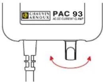
■ Once the PAC93 is connected to the device, adjust the zero by turning the potentiometer with no conductor in the jaws of the clamp.
text_image
CHAVIN ARNOUX PAC 93 AC-DC CURRENT CLAMP■ At the end of the measurement, remember to switch off the PAC93.
For the E94:
■ Connect the clamp to the measuring instrument.
■ Make sure that the clamp is not on a conductor and that its jaws are correctly closed.
■ Place the clamp in the position it will be in during the measurement.
■ Press the zero adjustment button.
■ The OL indicator lights for approximately three seconds to indicate that the zero adjustment is in progress in the two ranges.
If the zero has been correctly adjusted, the OL indicator goes off. If it remains on, the zero could not be adjusted.
For the clamps:
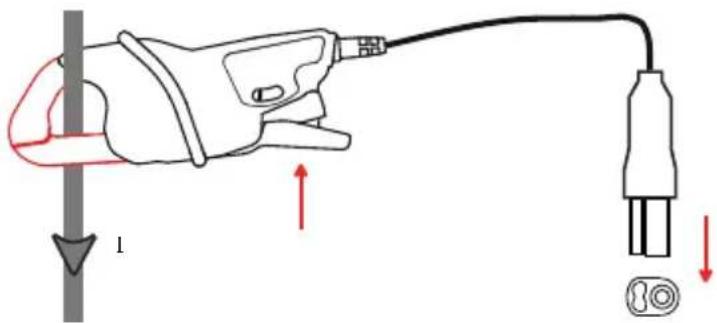
■ Press the trigger on the clamp to open the jaws.
■ Then clamp the cable that is to be measured. Where possible, the cable should be centred in the jaws of the clamp.
■ Release the trigger.
text_image
Diagram showing a hairpin connected to a plug with labeled parts and directional arrows indicating movement or force.For the MiniFlex models:
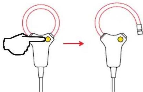
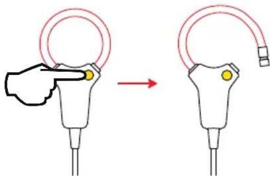
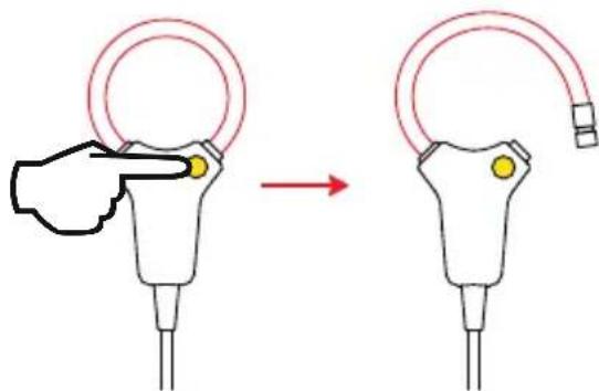
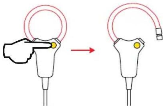
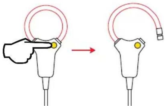
■ Press on the yellow opening device to open the flexible coil.
■ Open it and place it around the conductor carrying the current to be measured (only one conductor in the sensor). Where possible, the cable should be centred in the sensor.

text_image
Diagram illustrating a medical procedure with a hand pointing to a circular component before and after an operation.or
text_image
Diagram showing a hand pointing to a circular component before and after installation, with a yellow button on the device.■ Close the coil. You must hear the click.
For the AmpFlex® models:
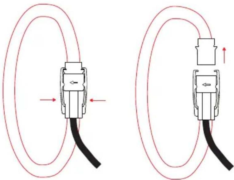
■ Press simultaneously on both sides of the opening device.
■ Then clamp the cable that is to be measured. Where possible, the cable should be centred in the sensor.
natural_image
Diagram showing two cable configurations with red wire loops and directional arrows indicating motion (no text or symbols)■ Close the sensor by forcing the moving part into the connector until you hear a click.
For details of the measurement configuration and technical characteristics, refer to the user manual of the analyser with which you are using the current sensor.
3.1. ENVIRONMENTAL CONDITIONS
Indoor use.
Operating range -10 °C to +55 °C and 10 % to 85% RH
Storage range -40 °C to +70 °C and 10 % to 90% RH
Degree of pollution 2
Altitude < 2000 m
3.2. CONSTRUCTION SPECIFICATIONS
MN93 and MN93A
■ Dimensions (L x W x H) 135 x 51 x 30 mm
■ Cord 3.50 metres long
■ Weight approx. 290 g
C193
■ Dimensions (L x W x H) 216 x 111 x 45 mm
■ Cord 3.50 metres long
■ Weight approx. 690 g
PAC93
■ Dimensions (L x W x H) 236.5 x 97 x 44 mm
■ Cord 3.50 metres long
■ Weight approx. 540 g
■ Battery life 120 hours with an alkaline battery
E94
■ Dimensions (L x W x H) 231 x 36 x 67 mm
■ Cord 3 metres long
■ Weight approx. 330 g
MINI94
■ Dimensions (L x W x H) 130 x 46 x 34 mm
■ Cord 3 metres long
■ Weight approx. 250 g
MiniFlex MA193 250 mm
■ Dimensions (L x W x H) approx. 130 x 80 x 12 mm
■ Cord 3 metres long
■ Weight approx. 110 g
MiniFlex MA194 250 mm
■ Dimensions (L x W x H) approx. 130 x 80 x 18 mm
■ Cord 3 metres long
■ Weight approx. 110 g
MiniFlex MA193 350 mm
■ Dimensions (L x W x H) approx. 170 x 110 x 12 mm
■ Cord 3 metres long
■ Weight approx. 120 g
MiniFlex MA194 and MA196 350 mm
■ Dimensions (L x W x H) approx. 170 x 110 x 18 mm
■ Cord 3 metres long
■ Weight approx. 120 g
MiniFlex MA194 1000 mm
■ Dimensions (L x W x H) approx. 370 x 320 x 18 mm
■ Cord 3 metres long
■ Weight approx. 160 g
AmpFlex® A193 450 mm
■ Dimensions (L x W x H) approx. 170 x 158 x 25 mm
■ Cord 3 metres long
■ Weight approx. 220 g
AmpFlex® A193 800 mm
■ Dimensions (L x W x H) approx. 280 x 265 x 25 mm
■ Cord 3 metres long
■ Weight approx. 270 g
AmpFlex® A196A 610 mm
■ Dimensions (L x W x H) approx. 215 x 200 x 25 mm
■ Cord 3 metres long
■ Weight approx. 250 g
Protection index
■ IP20 for the clamps E94 and MINI94, according to IEC 60529.
■ IP 40 for the clamps MN93, MN93A, C193 and PAC93, and IP 30 jaws open, according to IEC 60529
■ IP 50 for the MiniFlex MA193 and for the AmpFlex193 according to IEC 60529 in operation
■ IP 67 for the MiniFlex MA196 and MA194, and the AmpFlex196A according to IEC 60529 when the ring is screwed on
■ IK 04 according to IEC 62262.
Drop test: according to IEC/EN 61010-2-030 or BS EN 61010-2-030.
3.3. CONFORMITY TO INTERNATIONAL STANDARDS
Electrical safety according to IEC/EN 61010-2-032 or BS EN 61010-2-032.
Maximum appliable voltage:
■ MN93, MN93A, PAC93, E94, MINI94: 600 V category III or 300 V category IV
■ C193, MiniFlex, AmpFlex193: 1000 V category III or 600 V category IV
■ AmpFlex196A: 1000 V category IV
Type of current sensor as per IEC 61010-2-032:
■ MN93, MN93A, C193, PAC93, E94, MINI94: type A
■ MiniFlex, AmpFlextype B
4. MAINTENANCE
Except for the batteries, the instrument contains no parts that can be replaced by personnel who have not been specially trained and accredited. Any unauthorized repair or replacement of a part by an “equivalent” may gravely impair safety.
4.1. CLEANING
Disconnect the current sensor completely.
Use a soft cloth, dampened with soapy water. Rinse with a damp cloth and dry rapidly with a dry cloth or forced air. Do not use alcohol, solvents, or hydrocarbons.
Keep the air gaps of the clamps perfectly clean.
See to it that no foreign body interferes with the operation of the snap lock device of the sensor.
4.2. REPLACING THE BATTERY OF THE PAC93
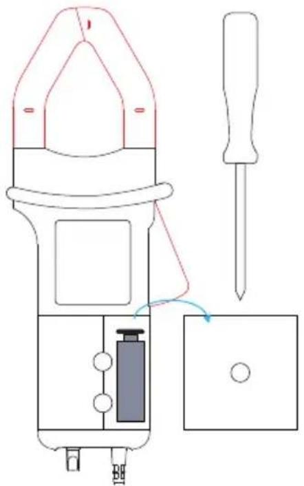
■ Disconnect the PAC93 completely and turn the rotary switch to OFF.
■ Turn the PAC93 over.
■ Use a screwdriver to unscrew the screws and remove the battery compartment cover.
text_image
Technical diagram of a plunger tool with labeled components and a screwdriver inserted into a box■ Withdraw the battery from its compartment without pulling on the wires.
■ Disconnect the old battery without pulling on the wires and connect the new one in its place, observing the polarity.

Spent batteries must not be treated as ordinary household waste. Take them to the appropriate recycling collection point.
■ Put the battery into its compartment.
■ Put the cover back in place and screw the screws back in.
5. WARRANTY
Except as otherwise stated, our warranty is valid for 24 months starting from the date on which the equipment was sold. The extract from our General Conditions of Sale is available on our website.
www.group.chauvin-arnoux.com/en/general-terms-of-sale
The warranty does not apply in the following cases:
■ Inappropriate use of the equipment or use with incompatible equipment;
■ Modifications made to the equipment without the explicit permission of the manufacturer's technical staff;
■ Work done on the device by a person not approved by the manufacturer;
■ Adaptation to a particular application not anticipated in the definition of the equipment or not indicated in the user's manual;
■ Damage caused by shocks, falls, or floods.
natural_image
Technical line drawing of a mechanical connector with threaded end and internal structure (no text or symbols)1.9. AMPFLEX® A193
text_image
Diagram showing a plunger, battery, and charging device with polarity indicatorstext_image
Diagram showing a hairdryer connected to a plug with labeled parts and directional arrows indicating force or movement.Für MiniFlex:
text_image
Diagram illustrating a medical procedure with a hand pointing to a bone structure before and after an operation.oder
text_image
Diagram showing a hand holding a circular device with a yellow button, before and after adjustment, indicating a change in the device's position.natural_image
Diagram showing two cable configurations with red arrows indicating direction of movement or force (no text or symbols present)MiniFlex MA193 250 mm
MiniFlex MA194 250 mm
MiniFlex MA193 350 mm
MiniFlex MA194 1000 mm
text_image
Diagram of a soldering iron with labeled components and a screwdriver inserted into a socketnatural_image
Technical line drawing of a mechanical connector with threaded end and internal ribbed structure (no text or symbols)1.9. AMPFLEX® A193
natural_image
Technical line drawing of a mechanical connector with threaded end and internal ribs (no text or symbols)1.11. CARATTERISTICHE DELLA CONSEGNA
Pinza PAC93
Sensore MiniFlex MA193 350 mm
Sensore MiniFlex MA194 250 mm
Sensore MiniFlex MA194 350 mm
Sensore MiniFlex MA194 1000 mm
Sensore MiniFlex MA196 350 mm
Sensore AmpFlex® A193 450 mm
Sensore AmpFlex® A193 800 mm
Sensore AmpFlex® A196A 610 mm
text_image
Diagram showing a plunger, battery, and charging device with polarity indicatorstext_image
Diagram showing a hairpin connected to a plug with labeled parts and directional arrows indicating force or movement.Per gli MiniFlex:
text_image
Diagram illustrating a medical procedure with hand pointing to a circular component and curved tube being inserted, showing directional change.oppure
text_image
Diagram showing a hand holding a circular device with a yellow button, before and after adjustment, indicating a change in the device's position.natural_image
Diagram showing two cable routing setups with red arrows indicating direction of movement (no text or symbols)MiniFlex MA193 250 mm
MiniFlex MA194 250 mm
MiniFlex MA193 350 mm
MiniFlex MA194 o MA196 350 mm
MiniFlex MA194 1000 mm
text_image
Technical diagram of a soldering iron with labeled components and a screwdriver inserted into a socketnatural_image
Technical line drawing of a mechanical connector with threaded end and internal structure (no text or symbols)1.9. AMPFLEX® A193
Sensor MiniFlex MA193 250 mm
Sensor MiniFlex MA193 350 mm
Sensor MiniFlex MA194 250 mm
Sensor MiniFlex MA194 350 mm
Sensor MiniFlex MA194 1000 mm
Sensor MiniFlex MA196 350 mm
Sensor AmpFlex® A193 450 mm
Sensor AmpFlex® A193 800 mm
Sensor AmpFlex® A196A 610 mm
text_image
Diagram showing a plunger, battery, and charging device with polarity indicatorstext_image
Diagram showing a hairclip connected to a plug with labeled parts and directional arrows indicating movement or force.Para los MiniFlex:
text_image
Diagram illustrating a medical procedure with a hand pointing to a circular component before and after a curved tube, showing directional change.0
text_image
Diagram showing a hand pointing to a device with a yellow dot, followed by a red arrow indicating transformation or change.natural_image
Two diagrams showing a connector with red arrows indicating direction, no text or symbols presentMiniFlex MA193 250 mm
MiniFlex MA194 250 mm
MiniFlex MA193 350 mm
MiniFlex MA194 1000 mm
text_image
Diagram of a soldering iron with labeled components including a screwdriver and switch, showing wiring connections.Our international contacts
www.chauvin-arnoux.com/contacts

CHAUVIN
ARNOUX