
Ottawq - Boiler EDILKAMIN - Free user manual and instructions
Find the device manual for free Ottawq EDILKAMIN in PDF.


| Product type | Wood pellet boiler (thermo-stove) |
| Brand | Edilkamin |
| Model | Ottawa |
| Fuel | Wood pellets diameter 6 mm, max length 40 mm, max humidity 8% |
| Nominal water power | 24 kW |
| Nominal power | 24 kW |
| Overall efficiency | Approximately 91.9% |
| Tank capacity | 100 kg |
| Autonomy min/max | 18 / 65 hours |
| Fuel consumption min/max | 1.5 / 5.4 kg/h |
| Indicative heated volume | 625 m³ |
| Max pressure | 3 bar |
| Operating pressure | 1.5 bar |
| Flue gas outlet temperature | 97 °C |
| Flue pipe diameter | 10 cm |
| Power supply | 230 V ±10%, 50 Hz |
| Average electrical power consumption | 120 W |
| Electrical power at ignition | 400 W |
| Weight with packaging | 355 kg |
| Dimensions (W x D x H) | See diagram in the manual |
| Hydraulic connections | Hot water outlet 3/4" M, water return 3/4" M, domestic hot water 1/2" M |
| Control system | Leonardo® with pressure and temperature sensors |
| Remote controls | Radio remote control (Ottawa) and infrared remote control depending on version |
| Safety devices | Thermocouple, vacuum gauge, water safety thermostat, tank safety thermostat, pressure relief valve |
| DHW production | Integrated, instantaneous without storage |
| Routine maintenance | Weekly cleaning of the crucible, ash pan, glass; monthly emptying of the tank |
| Seasonal maintenance | By authorized dealer (general cleaning, checking seals, expansion tank, etc.) |
| Warranty | Conditional upon commissioning by an Edilkamin approved center |
Frequently Asked Questions - Ottawq EDILKAMIN
User questions about Ottawq EDILKAMIN
0 question about this device. Answer the ones you know or ask your own.
Ask a new question about this device
Download the instructions for your Boiler in PDF format for free! Find your manual Ottawq - EDILKAMIN and take your electronic device back in hand. On this page are published all the documents necessary for the use of your device. Ottawq by EDILKAMIN.
USER MANUAL Ottawq EDILKAMIN
natural_image
Four industrial water filter units with visible internal structures and ventilation grilles, shown from different angles (no text or symbols)UK Installation, use and maintenance p. 28
F Installation, usage et maintenance p. 54
natural_image
Close-up of a metallic electrical component with wires and a star-like mark (no visible text or symbols)PORTA SERIALE

natural_image
Technical diagram of a mechanical assembly with pipes and components (no visible text or labels)Circolatore
natural_image
Simple 3D diagram of a curved surface with a small symbol at the top (no text or labels)vista del finito
MONTAGGIO RIVESTIMENTI
natural_image
Mechanical assembly diagram showing a device with labeled components C, D, and directional arrows (no text or symbols beyond labels)natural_image
3D diagram of a dual-panel electronic device with labeled ports (no text or symbols beyond labels)natural_image
Exterior view of a modern office building (no signage)vista del finito
natural_image
3D rendering of a mechanical device with an open lid and internal component (no visible text or symbols)fissaggio
natural_image
3D rendered model of a vehicle or engine component with no visible text or symbolsvista del finito
4/3
natural_image
Metallic cylindrical object with labeled corner brackets (I) and letter G, no additional text or symbols visible.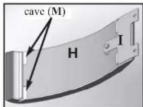
4/4
natural_image
Exterior view of a black industrial device casing with ventilation slots and a lid (no visible text or symbols)montaggio ceramiche
vista fianco sinistro E

natural_image
3D rendering of a mechanical device with two labeled components (C), no visible text or symbols on the device itself.vista fianco destro F
natural_image
Interior view of a server rack with three circular panels showing various object categories (no visible text or labels)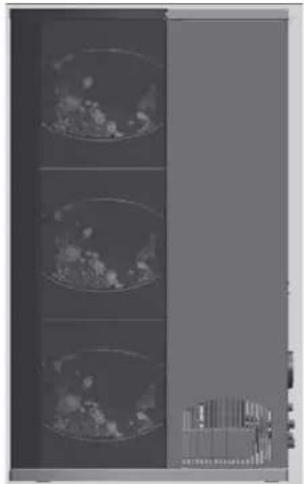
natural_image
Three vertical panels showing close-up of a textured surface with no visible text or symbols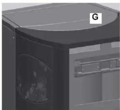
natural_image
3D rendering of a mechanical device with a labeled component 'G' (no text or symbols on the device itself)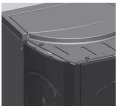
natural_image
Close-up of a black industrial machine casing with visible internal components and mounting brackets (no text or symbols)MONTAGGIO RIVESTIMENTI
QUEBEC / DETROIT
| n° cod. | |||
| 1 | Frontalino inf. rosso 1 642050 | ||
| 1 | Frontalino inf. panna 1 642040 | ||
| 2 | Frontalino sup. rosso 1 642070 | ||
| 2 | Frontalino sup. panna 1 642060 | ||
| 3 | Fianco grande rosso 2 642090 | ||
| 3 | Fianco grande panna | 2 642080 | |
| 4 | Fianco piccolo rosso 6 46160 | ||
| 4 | Fianco piccolo panna | 6 645750 | |
| 5 | Top rosso 1 642130 | ||
| 5 | Top panna 1 642120 | ||
| 6 | Vite T.b. 6x12 12 284380 | ||
| 7 | Piastrine ceramiche 10 647670 | ||
| 8 | Vile 4,8x10 | 16 266940 | |
| 9 | Bloccaggio ceramica anta | 2 387530 | |
| 10 | Bloccaggio ceramica frontale | 2 388890 | |
| 11 | Vite T.E.6x16 | 2 18650 | |
| 12 | Vite 4,2x6,5 | 2 235990 | |
| 13 | Distanziale | 6 266670 | |
TORONTO / BOSTON
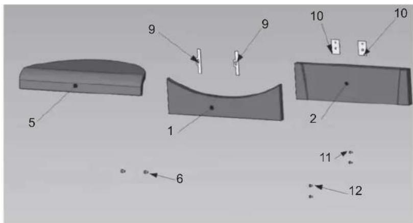
| pz | cod. | ||
| 1 | Frontalino inferiore rosso | 1 642050 | |
| 1 | Frontalino inferiore panna | 1 642040 | |
| 2 | Frontalino superiore rosso | 1 642070 | |
| 2 | Frontalino superiore panna | 1 642060 | |
| 5 | Top rosso | 1 642130 | |
| 5 | Top panna | 1 642120 | |
| 6 | Vite T.B. 6x12 | 2 284380 | |
| 9 | Bloccaggio ceramica anta | 2 387530 | |
| 10 | Bloccaggio ceramica frontale | 2 388890 | |
| 11 | Vite T.F. 6x16 | 2 | 18650 |
| 12 | Vite 4,2x6,5 | 2 235990 | |
MONTREAL / MIAMI
natural_image
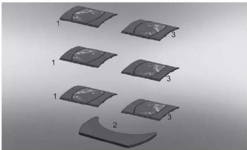
Diagram showing six stages of a curved, segmented object with numbered labels (1, 2, 3, 4), no text or symbols present.| pz | cod. | ||
| 1 | Fianco destro | 3655220 | |
| 2 | Top | 1655210 | |
| 3 | Fianco sinistro | 3657430 | |
ISTRUZIONI D'USO
Pannello sinottico

natural_image
Close-up of a handheld electronic device with a display showing '254' and control buttons (A, B, C, D) on its body.

natural_image
Close-up of a handheld electronic device with a digital display showing '254' and control buttons (no readable text beyond symbols)

fig. B
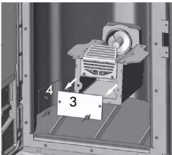
fig. C fig. D
natural_image
Mechanical assembly diagram showing a motor inside a frame with a labeled component '4' (no text or symbols beyond label)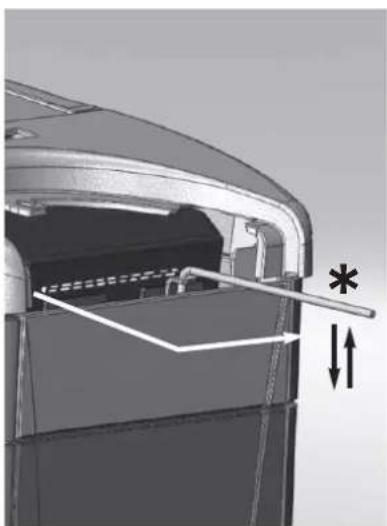
natural_image
Diagram of a mechanical component with internal structure and directional arrows (no text or symbols)fig. E fig. F
natural_image
3D mechanical assembly diagram showing internal components with arrows indicating motion (no text or symbols)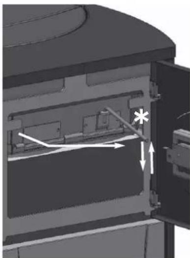
natural_image
3D mechanical assembly diagram showing internal components and directional arrows (no text or symbols)fig. G
POSSIBILI INCONVENIENTI
CHECK LIST
Congratulations and thank you for choosing our product.
Please read this document carefully before you use this product in order to obtain the best performance in complete safety.
For further details or assistance, please contact the DEALER where you purchased the product or visit the TECHNICAL
ASSISTANCE CENTRES page on our website www.edilkamin.com.
NOTE
- After you remove the packaging, please inspect the unit for any damage or missing parts (cladding, remote control with display, "stay cool" handle, warranty booklet, glove, technical data sheet, spatula, desiccant, hex key).
In case of anomalies please contact the dealer where you purchased the product immediately. You will need to present a copy of the warranty booklet and valid proof of purchase.
- Commissioning/ testing
Commissioning and testing must be performed by an authorized Edilkamin Technical Assistance Centre. Failure to do so will void the warranty. Commissioning, as specified in standard UNI 10683 consists in a series of controls performed on the installed stove in order to ascertain the correct operation of the system and its compliance to applicable regulations.
To locate the Technical Assistance Centre closest to you, please ask your local dealer, call our toll-free number, or visit our website www.edilkamin.com.
- Incorrect installation, incorrect maintenance, or improper use of the product, shall relieve the manufacturer from any damage resulting from the use of this product.
- the proof of purchase tag, necessary for identifying the stove, is located:
- on the top of the package
- in the warranty booklet found inside the firebox
- on the ID plate affixed to the back side of the unit;
This documentation must be saved for identification together with the valid proof of purchase receipt. The data contained therein must be reported when requesting information and made available should servicing be required;
- All images are for illustration purposes only; actual products may vary.
SAFETY INFORMATION
THE THERMO-STOVE MUST NEVER BE MADE TO OPERATE WITHOUT WATER IN THE SYSTEM NOR AT A PRESSURE OF LESS THAN 1 BAR.
IT CAN BE DAMAGED IF IT IS IGNITED WITH NO WATER IN THE SYSTEM.
- The thermo-stoves is designed to heat water by means of automatic combustion of pellets (wood with 6 mm diameter) in the hearth.
• The only risks that may derive from using the thermo-stoves pertain to non-compliance with the installation regulations, direct contact with live electrical parts (internal), contact with the fire or hot parts, or foreign substances being put into the stove.
- Should components fail, the thermo-stoves is equipped with safety devices to guarantee its automatic shutdown.
• These are activated without any intervention required.
- In order to function correctly, the thermo-stoves must be installed in accordance with the instructions given herein.
- Whilst functioning, the door must never be opened. In fact, combustion is fully automatic and requires no manual intervention.
- Under no circumstances should any foreign substances be put into the hearth or the hopper.
- Do not use flammable products to clean the smoke discharge duct.
- Use a vacuum cleaner to clean the hearth and hopper, when COLD.
- The glass can be cleaned when COLD with a suitable product (e.g. GlassKamin) and a cloth. Do not clean when hot.
- Whilst the thermo-stoves is in operation, the exhaust pipes and door become very hot.
- Do not place anything that is not heat resistant near the thermo-stoves
- NEVER use liquid fuel to ignite the thermo-stoves or rekindle the embers.
- Do not obstruct the external air inlets in the room where the stove is installed, nor those of the thermo-stoves itself.
- Do not wet the thermo-stoves and do not go near electrical parts with wet hands.
- Do not use reducers on the smoke exhaust pipes.
- The thermo-stoves must be installed in a room that is suitable for fire prevention and equipped with all that is required (power and air supply and outlets) for the stove to function correctly and safely.
- The thermo-stoves must be kept in a room where the temperature is above 0^ .
- Use appropriate anti-freeze additives for the water of the system.
- Ensure that the temperature of the return water is at least 45^ .
Should ignition fail, DO NOT re-ignite until you have emptied the combustion chamber.
The undersigned EDILKAMIN S.p.a. with head office headquarters at Via Vincenzo Monti 47 - 20123 Milan - Italy - VAT T00192220192
Declares under its own responsibility as follows:
The pellet Boiler-stoves illustrated below conforms to Regulation EU 305/2011 (CPR) and to the harmonised European Standard EN 14785:2006 WOOD PELLET BOILER-STOVES, trademark EDILKAMIN, called QUEBEC - TORONTO - MONTREAL - DETROIT - BOSTON - MIAMI
Year of manufacture: Ref. Data nameplate
Declaration of performance (DoP - EK 051-059): Ref. data tag plate
The pellet boiler illustrated below conforms to the Machinery Directive 2006/42/EC and to the harmonised European Standard EN 303-5:2012 WOOD PELLET BOILER, trademark EDILKAMIN, called OTTAWA - ATLANTA
Year of manufacture: Ref. Data nameplate
Declaration of Conformity
The wood pellet Boiler-stoves QUEBEC - TORONTO - MONTREAL - DETROIT - BOSTON - MIAMI and pellet Boiler OTTAWA-ATLANTA is in compliance with the requirements of the European directives:
2006/95/EEC - Low voltage directive
2004/108/EEC - Electromagnetic compatibility directive
EDILKAMIN S.p.a. will decline all responsibility of malfunctioning or damage to the equipment in case of unauthorized substitution, assembly or modifications of any sort on the said equipment on the part of non-EDILKAMIN personnel.
DIMENSIONS
QUEBEC - TORONTO
DETROIT - BOSTON
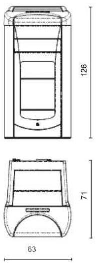
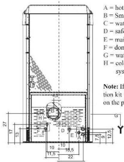
A = hot water outlet 3/4" M
B = Smoke outlet (∅ 10 cm)
C = water return line 3/4" M
D = safety valve drainage 1/2" F
E = mains water 1/2" M
F = domestic hot water 1/2" M
G = water drainage (left side)
H = cold water from the plumbing system 1/2" M
Note: If the internal ACS production kit is not utilized, caps F and H on the pipes must not be removed.
MONTREAL - MIAMI
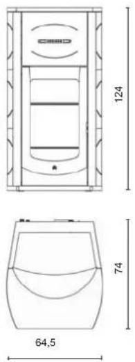
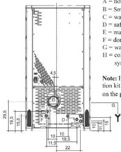
A = hot water outlet 3/4" M
B = Smoke outlet (∅ 10 cm)
C = water return line 3/4" M
D = safety valve drainage 1/2" F
E = mains water 1/2" M
F = domestic hot water 1/2" M
G = water drainage (left side)
H = cold water from the plumbing system 1/2" M
Note: If the internal ACS production kit is not utilized, caps F and H on the pipes must not be removed.
OTTAWA - ATLANTA
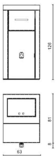
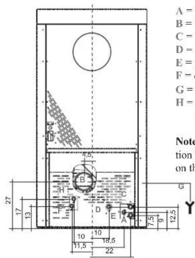
A = hot water outlet 3/4" M
B = Smoke outlet (∅ 10 cm)
C = water return line 3/4" M
D = safety valve drainage 1/2" F
E = mains water 1/2" M
F = domestic hot water 1/2" M
G = water drainage (left side)
H = cold water from the plumbing system 1/2" M
Note: If the internal ACS production kit is not utilized, caps F and H on the pipes must not be removed.
FEATURES
TECHNICAL AND HEATING SPECIFICATIONS
| QUEBEC/TORONTOMONTREAL | DETROIT/BOSTONMIAMIO | TTAWA ATLANTA | |||
| Hopper capacity | 60 | 60 | 100 | 100 | kg |
| Approx. overall efficiency | 93,3 | 93,2 | 91,9 | 91,2 | % |
| Rated power | 24 | 32,6 | 24 | 32,3 | kW |
| Water heating power | 21 | 29,3 | 24 | 32,3 | kW |
| Min./max. autonomy | 11 / 38 | 8 / 26 | 18 / 65 | 13/ 44 | hores |
| Fuel consumption min./max. | 1,5 / 5,4 | 2,2 / 7,3 | 1,5 / 5,4 | 2,2 / 7,4 | kg/h |
| Minimum draught | 12 / 5 | 12 / 5 | 12 / 5 | 12 / 5 | Pa |
| Max. pressure | 3 | 3 | 3 | 3 | bar |
| Operating pressure | 1,5 | 1,5 | 1,5 | 1,5 | bar |
| Smoke output temperature from test EN14785 | 114 | 142 | 97 | 142 | °C |
| CO emission (13% O2) | 0,011 | 0,012 | 0,013 | 0,013 | % |
| Weight including packing | 390 / 370 / 360 | 390 / 370 / 359 | 355 | 370 | kg |
| Heating capacity * | 625 | 850 | 625 | 840 | m^3 |
| Diameter of smoke extract duct male thread | 10 | 10 | 10 | 10 | cm |
* The heatable room dimensions are calculated on the basis of pellets with an lhy of at least 4300 kcal/kg and home insulation in compliance with Italian law 10/91, and subsequent changes together with an expected heat output of 33 Kcal/m³ per hour.
It is also important to consider the position of the thermo-stoves in the room to be heated.
A LOT DEPENDS ON THE EFFICIENCY OF THE SYSTEM TERMINALS (heaters).
N.B.
1) Bear in mind that external devices may cause interference.
2) Warning: work on live components, maintenance and /or checks must be performed by qualified personnel.
(Before carrying out any maintenance, disconnect the device from the mains power supply)
ELECTRICAL CHARACTERISTICS
| Power supply 230Vac +/- 10% 50 Hz | ||
| On/off switch yes | ||
| Average power consumed 120 W | ||
| Average power consumed upon ignition 400 W | ||
| Radio control / Remote control frequency Radio waves 2.4 GHz / Infrared | ||
| Main power supply protection ** ** Fuse 2A, 250 VAC 5x20 | ||
| Electronic control board protection ** Fuse 2A, 250 VAC 5x20 | ||
The data shown above is purely indicative.
EDILKAMIN reserves the right to make changes to these products to improve their performance with no prior warning.
SAFETY DEVICES
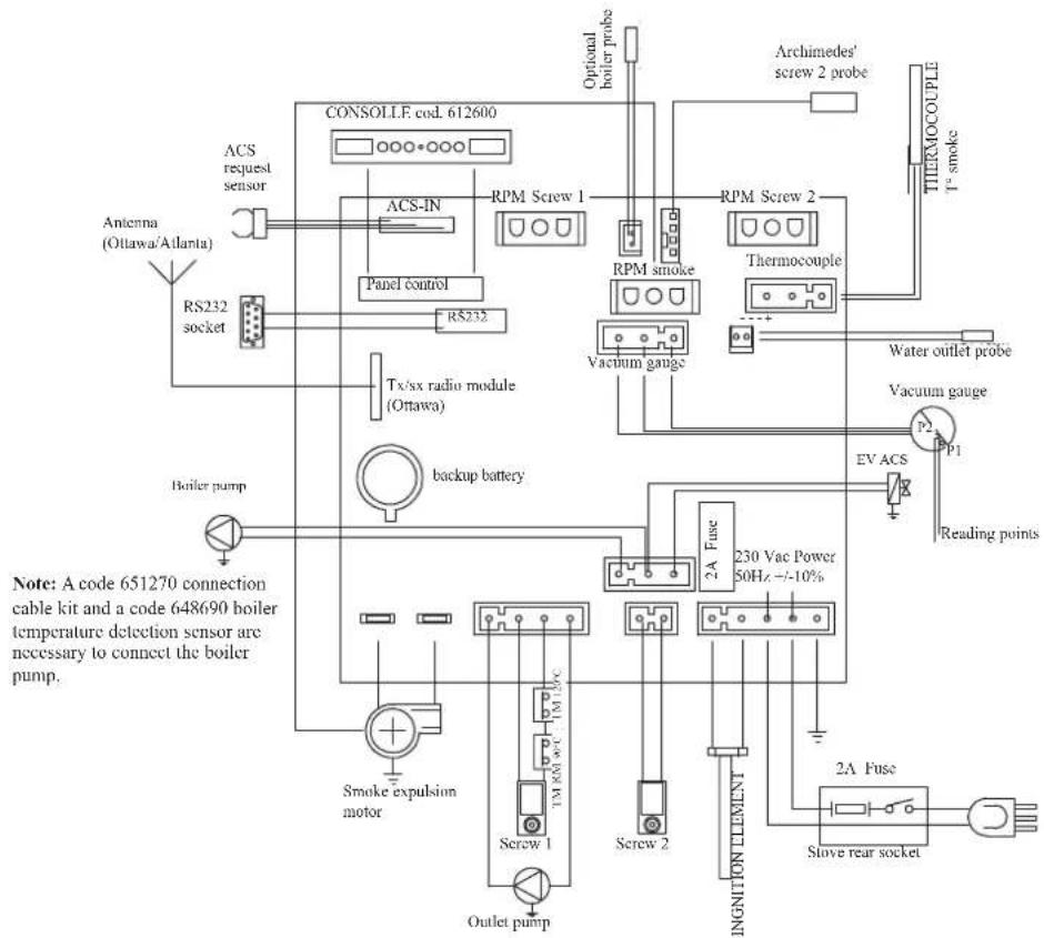
THERMOCOUPLE:
| placed at the smoke outlet to detect the temperature. Turns the thermo-stoves on and off and controls its operation based on defined parameters. |
VACUUM GAUGE (electronic pressure sensor):
| positioned on the smoke extractor, which detects the vacuum value (compared to the installation environment) in the combustion chamber. |
WATER SAFETY THERMOSTAT:
| trips when the temperature inside the thermo-stoves is too high. |
| It stops pellet loading, causing the thermo-stoves to go out. Reset manually. |
TANK SAFETY THERMOSTAT:
| trips when the temperature inside the thermo-stoves is too high. |
| It stops pellet loading, causing the thermo-stoves to go out. |
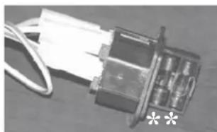
FUSE**
| two fuses are inserted in the socket with switch, located on the back of the stove, one of which operational and the other is held in reserve. |
natural_image
Close-up of a small electronic component with wires and connectors (no visible text or symbols)SERIAL PORT
The Dealer can install an optional on the AUX outlet for controlling the process of switching on and off (e.g. telephone remote, local thermostat), located at the rear oh the stove. Can be connected via special optional trestle (code 640560).
BACKUP BATTERY
A backup battery is found on the control board (3-Volt CR 2032 battery). Its malfunction is indicated with the following messages (not considered a defect but due to normal wear-and-tear): "Battery Check".
For more detailed information, please contact the DEALER who has performed the first 1st ignition.
FEATURES
ELECTRONIC CIRCUIT BOARD
The pellet thermo-stoves are equipped with the LEONARDO® SYSTEM, which provides for optimal combustion.
LEONARDO® ensures excellent operation thanks to two sensors measuring the pressure level in the combustion chamber and smoke temperature. The detection of and subsequent optimisation of these two parameters is continuous in order to correct operation anomalies in real time.
The LEONARDO® system offers constant combustion, automatically regulating the draft based on the characteristics of the chimney flue (bends, length, shape, diameter, etc.) and environmental conditions (wind, humidity, atmospheric pressure, installations at high altitude, etc.). The standards for installation must be respected.
LEONARDO® system is also able to recognise the type of pellets and automatically adjust the flow moment by moment to ensure the required level of combustion (use wood pellets with a diameter of approximately 6 mm).
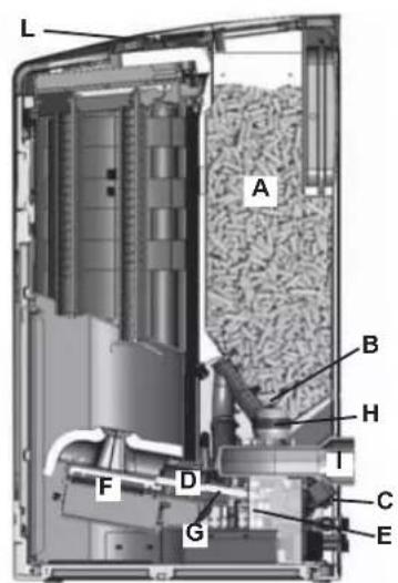
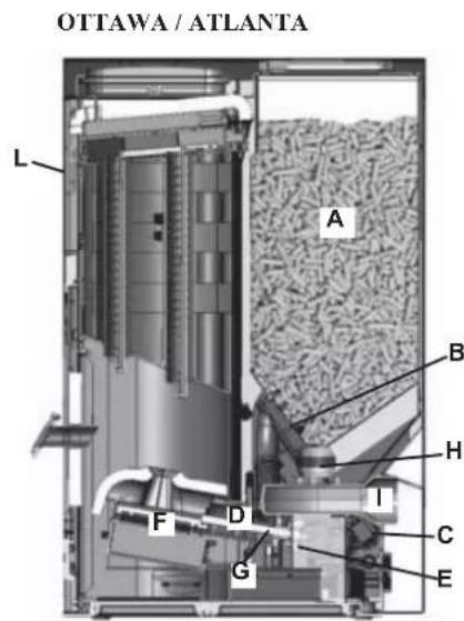
The thermo-stoves is fuelled by pellets. These are little, cylindrical shapes of pressed wood whose combustion is controlled electronically. The heat produced by combustion is mainly transmitted to the water and partly emitted into the room by radiation.
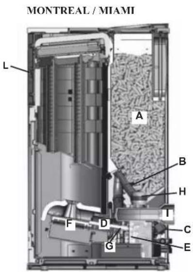
The fuel tank ( ) is located at the rear of the thermo-stoves. Filling the tank is through the back of the lid at the rear of the top.
The fuel (pellets) is taken from the storage tank (A) and, via an Archimedes' screw (B) activated by a gear motor (C), is transported into a second Archimedes' screw (D) activated by a second gear motor (E) it is then transported to the combustion crucible (F).
The ignition of the pellet is via air heated by an electrical heating element (G) and is sucked into the crucible by a smoke extractor (H). The combustion air is drawn into the room (where there must be an air intake) smoke extractor (H).
The smoke produced by combustion, is extracted from the thermo-stoves through the smoke extractor (H), and expelled from the pipe union (I) located in the bottom portion of the rear of the thermo-stoves. The ash falls under and beside the crucible in which is housed an ash tray from which the ash must be periodically removed by vacuuming when cool.
The hot water produced by the thermo-stoves is transferred via a circulator built into the stove itself, to the heating system circuit. The thermo-stoves also contains a built in kit for producing hot water.
The thermo-stoves is designed to function with closed expansion tank and pressure valve, both of which are built in. Fuel quantity, smoke extraction/combustion air supply and pump activation are regulated by the control board, which is equipped with Leonardo® software to achieve high combustion efficiency and low emissions.
The synoptic panel (L)(on the front for Montreal / Miami / Ottawa / Atlanta) is installed on the top, through which all phases of operation can be displayed and controlled. The main phases can even be handled by radio control (Ottawa / Atlanta model) and remote control (Quebec / Toronto / Montreal / Detroit / Boston / Miami models). Aserial port is found at the back of the thermo-stoves (optional cable: code 640560) to be connected to devices that allow remote ignition (e.g. remote telephone, local thermostat).
Operating modes
(for further details, please see page 42)
The temperature of the water required in the system is set via the panel (standard recommendation 70^ C) and the stove manually or automatically modulates the power to maintain or reach this temperature. The Eco function can be enabled in small systems (the thermo-stoves shuts down and goes on again according to the water temperature required).
QUEBEC / TORONTO
DETROIT / BOSTON

NOTE regarding the fuel.
The pellet thermal stoves are designed and programmed to burn wood pellets, 6 mm in diameter.
Pellets are a type of fuel made from compacted sawdust and chopped waste wood, compressed under high pressure with no adhesives or foreign materials. They are small in size, approximately 6 mm in diameter and have a cylindrical shape.
They are sold in bags of 15 kg.
For the thermal thermo-stoves to function properly, you MUST NOT burn anything else in it.
Using other materials (including wood) will render the warranty null and void. Such use is detected by laboratory analyses.
Edilkamin has designed, tested and programmed their stoves to guarantee the best performance when pellets with the following characteristics are used:
diameter: 6 millimetres;
maximum length: 40 mm;
maximum moisture content: 8 %;
calorific value: at least 4300 kcal/kg
Using unsuitable pellets may: decrease efficiency; cause malfunctions; stop the stove from functioning due to clogging, dirt on the glass, unburnt fuel, etc.
Refer to CTI recommendations available from the website www.cti2000.it.
SAFETY AND DETECTION DEVICES
Smoke thermocouple
placed on the smoke exhaust pipe to detect the temperature. It controls the ignition phase and if the temperature is too high or too low it triggers a block phase (Stop Flame or Overheated Smoke).
Feed Screw safety thermostat
placed near the pellet hopper. It disconnects the electrical supply to the gear motor if the temperature detected is too high.
Water temperature sensor
detects the water temperature in the thermo-stoves and transmits this to the information card to manage the pump and adjust the power. If the temperature is too high, a block phase is triggered.
Water overheating safety thermostat
detects the water temperature in the thermo-stoves. If this is too high, it triggers the shutdown process by disconnecting the electrical supply to the gear motor. In the event that the thermostat has been operated, it must be re-activated by acting on the reset button behind the thermo-stoves (see page. 52).
Overpressure valve
upon reaching the pressure stipulated on the plate, the system is triggered to discharge the water and consequently the water must be topped up.
WARNING!!!! remember to carry out the connection with the sewage system.
Manometer
placed on the side of the thermal thermo-stoves (at the rear for the Ottawa model), it allows you to read the water pressure in the thermal thermo-stoves. With the thermal thermo-stoves running, the recommended pressure is 1bar (see page. 42).
Microswitch door opening detection (Boston - Detroit - Miami - Atlanta)
Electro-hydraulic pressure switch (Boston - Detroit - Miami - Atlanta)
IF THE THERMAL THERMO-STOVES BLOCKS, THE REASON WILL APPEAR ON THE DISPLAY AND THIS WILL BE SAVED.
COMPONENTS
Resistance
triggers pellet combustion. It remains on until the smoke temperature increases by 15 ^ from that prior to ignition.
Smoke extractor
"pushes" the smoke into the flue and draws out combustion air via a vacuum.
No. 2 Gear motors
Activate the Archimedes' screw allowing the transportation of the pellets from the storage tank to the crucible.
Pump (circulator)
"pushes" water toward the heating system.
Closed expansion tank
'absorbs' changes in the volume of the water contained in the thermal thermo-stoves.
A heating technician must evaluate the need to add a second tank to the existing one, depending on total amount of water in the system.
Venting valve:
positioned in the upper part, it allows for the "bleeding" of any air present during the loading of water inside the thermo-stoves.
Drain tap
placed inside the lower part of the thermal thermo-stoves. This is to be opened if the water inside the thermal thermo-stoves must be emptied.
Incorporated kit for hot tap water
Allows for the production of hot tap water instantaneously, or rather with no accumulation.
INSTALLATION
Refer to local regulations in the country of use for anything that is not specifically covered in this manual. In Italy, refer to standards UNI 10683 and UNI 10412-2, as well as the Ministerial Decree No. 37, ex Law No. 46/90, in addition to any Regional or Local Health Authority regulations. If installing in a block of apartments, first consult the block administrator.
Verify compatibility with other devices
According to standard UNI 10683/2005, the thermo-stoves must NOT be installed in the same room as extractors, type A and B gas appliances and, in any case, devices that diminish the ventilation inside the room.
Check electrical connections (POSITION THE SOCKET IN AN ACCESSIBLE PLACE)
The stove is equipped with a electrical power cable to be connected to a 230V 50 Hz socket, preferably with a magnetothermic switch. Voltage variations exceeding 10% can damage the thermo-stoves (unless already installed, an appropriate differential switch must be fitted). The electrical system must comply with law; particularly verify the efficiency of the earthing system. The power line must have suitable cross-section for the thermo-stoves's power. Lack of efficiency of the "ground" circuit causes malfunction for which Edilkamin cannot be held responsible.
Positioning
The thermo-stoves must be level for it to function correctly. Verify the bearing capacity of the floor.
Fire prevention safety distances
The thermo-stoves must be installed in compliance with the following safety conditions:
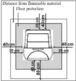
- medium flammability items must be kept at a minimum distance of 20 cm from the sides and back of the thermo-stoves
- highly flammable items must be kept at a minimum distance of 80 cm if placed in front of the thermo-stoves
- if the thermo-stoves is installed on flammable flooring, a sheet of heat insulating material must be placed on the floor. This must extend at least 20~cm from the sides and 40~cm from the front.
Flammable objects must not be placed above the thermo-stoves or at a distance that is any less than the stipulated safety distances. If connected to wooden walls or other flammable materials, the smoke exhaust pipe must be appropriately insulated with ceramic fibre or other similar material.
Air inlet: to be mandatorily implemented.
The room where the thermo-stoves is placed must have an air inlet with a cross-section of at least 80~cm^2 so as to guarantee sufficient air supply to the stove for combustion.
Smoke outlet
The discharge system must only be used for the thermo-stoves (the smoke cannot be discharged into a chimney flue used by other devices).
The smoke is discharged through the 10 cm diameter outlet at the back of the thermo-stoves. A T-junction must be set up with a condensation collection stopper at the beginning of the vertical section. The thermo-stoves smoke discharge must be connected with outside by means of steel or black pipes EN 1856 certified.
The pipe line must be hermetically sealed. The pipes must be sealed and insulated using materials that are resistant to high temperatures (high temperature silicone or mastic). The only horizontal section allowed may be up to 2 m long. The horizontal section must have a minimum inclination of 3% and a maximum of two 90° bends. If the outlet is not fitted into a chimney flue, a vertical section of at least 1.5 m will be required, complete with a wind guard. The vertical duct can be internal or external. If the smoke channel is outside, it must be insulated.
If the smoke channel is fitted inside a chimney flue, the latter must be suitable for solid fuel. If it is wider than 150 mm in diameter, a pipe must be entered and the outlet sealed to the masonry. All sections of the smoke duct must be accessible for inspection.
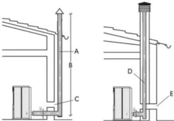
A: insulated steel chimney flu, Insulated
B: minimum height 1.5 m, and however beyond the eaves of the roof
C-E: air intake from outside (through section at least 80 cm²)
D: steel chimney flue inside existing masonry chimney flue
HYDRAULIC CONNECTIONS
(Reserved for DEALER)
The stoves have a boiler with a capacity of 80 Lts. of water. This significant amount of water renders the stove extremely smooth in operation, little affected by variations in demand of users. This will provide for highly consistent combustion with excellent yield. The stoves are equipped with a kit for producing instant Domestic Hot Water for bathrooms and kitchens as well as kits for the heating system (circulator, safety, loading and unloading). The stoves are also equipped with a solenoid valve that, in the start-up phase plays a very useful RECIRCULATION function; moving the water inside the stove, and speeding up the heating phase. The hydraulic connection must be performed by qualified personnel who can issue a declaration of conformity according to the Ministerial decree no. 37 ex L.46/90. Reference must however be made to the laws in force in the individual countries.
Water treatment
Foresees the addition of antifreeze, de-scaling and corrosion substances. In the event that the water used for filling and topping up has a hardness greater than 35^ F, use a water softener. For suggestions please refer to regulation UNI 8065-1989 (Water Treatment In Heating Systems For Civil Use).
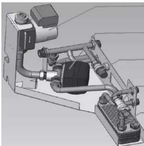
The following is a schematic diagram of the hydraulic kit built into the stove for instant production (without accumulation) of ACS.
natural_image
Mechanical assembly diagram showing internal components like hoses, pipes, and housing (no text or labels)Circulator
The Ottawa is equipped with a circulator with a new generation electronic motor.
3-way valve
Safety Valve
Flow meter
Plate heat exchanger
THE ELECTRONIC CIRCULATOR
The Ottawa is equipped with a circulator with a new generation electronic motor.
Electronic control of operation:
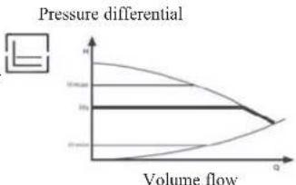
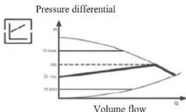
a) Control mode p - c In this mode, the electronic controller keeps the differential pressure generated by the pump at a constant set value of H s.
line
| Volume flow | Pressure differential | | ----------- | -------------------- | | 0 | 0 | | 1 | -1 | | 2 | -2 | | 3 | -3 | | 4 | -4 | | 5 | -5 | | 6 | -6 | | 7 | -7 | | 8 | -8 | | 9 | -9 | | 10 | -10 |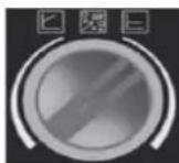
b) Control mode p - v
In this mode, the electronic controller varies the pressure differential between the set value Hs and 1/2 Hs. The pressure differential varies with the volume flow.
line
| Volume flow | H min | H 1s | H max | | ----------- | ----- | ---- | ----- | | Q | 0 | 0 | 0 | | H | 0 | 0 | 0 | | Q | 0 | 0 | 0 |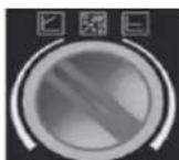
c) Venting procedure
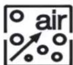
This procedure allows the expulsion of air present in the hydraulic circuit. After manual selection of the "AIR" mode, the pump will automatically alternate between maximum and minimum speed for 10 minutes. At the end of the procedure, the circulator will go to the pre-set speed. You can then select the desired mode of operation
HYDRAULIC CONNECTIONS
Hydraulic schematic diagram of built in kit.
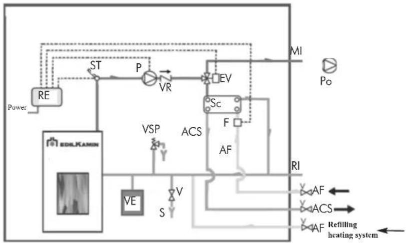
flowchart
graph TD
    A["Power"] --> B["RE"]
    B --> C["ST"]
    C --> D["P"]
    D --> E["VR"]
    E --> F["EV"]
    F --> G["MI"]
    G --> H["Po"]
    I["EDILKAMIN"] --> J["VE"]
    J --> K["VSP"]
    K --> L["ACS"]
    L --> M["Sc"]
    M --> N["F"]
    N --> O["AF"]
    O --> P["RI"]
    P --> Q["AF"]
    P --> R["ACS"]
    P --> S["AF"]
    T["Refilling heating system"] --> U["Power"]
KEY
ACS: Domestic Hot Water
AF: Cold Water
MI: System delivery
EV: 3 way Solenoid valve
F: Flow meter
P: Pump (circulator)
Po: Pump OPTIONAL
RE: Electronic Regulator
RI: System Return
S: Drainage
Se: Exchanger
ST: Temperature Probe
V:Valve
VE: Expansion tank
VR: Check Valve
VSP: Safety valve
VST: Thermal discharge valve
The following are some schematic diagrams indicative of possible systems.
Heating system combined with boilers.
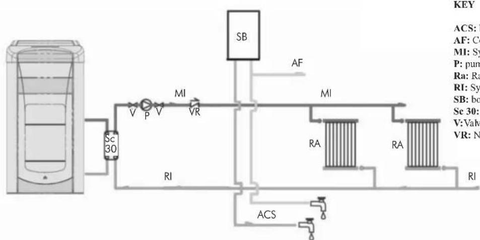
flowchart
graph TD
    A["Sc 30"] --> B["V"]
    B --> C["P"]
    C --> D["V"]
    D --> E["MI"]
    E --> F["VR"]
    F --> G["RI"]
    G --> H["ACS"]
    H --> I["RI"]
    I --> J["RA"]
    J --> K["RA"]
    K --> L["SI"]
    L --> M["AF"]
    M --> N["SB"]
    style A fill:#f9f,stroke:#333
    style N fill:#ccf,stroke:#333
KEY
ACS: Domestic Hot Water
AF: Cold Water
MI: System delivery
P: pump (circulator)
Ra: Radiators
RI: System Return
SB: boiler
Sc 30: 30 Plate Exchanger
V:Valve
VR: Non-return valve
Heating system with single source of heat for the production of heat and domestic hot water
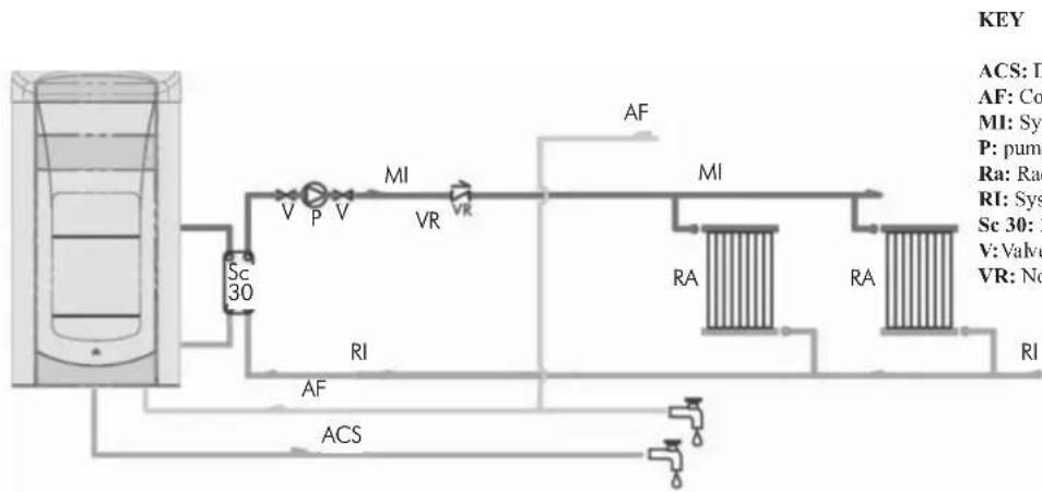
flowchart
graph TD
    A["Water Tank"] --> B["Sensor"]
    B --> C["MI"]
    C --> D["RA"]
    D --> E["RA"]
    E --> F["RI"]
    F --> G["ACS"]
    G --> H["Flow Meter"]
    I["Sc 30"] --> J["Valve"]
    K["AF"] --> L["Valve"]
    M["PI"] --> N["Valve"]
    O["VR"] --> P["Valve"]
    Q["MI"] --> R["Valve"]
    S["RA"] --> T["Valve"]
    U["VA"] --> V["Valve"]
    W["VA"] --> X["Valve"]
    Y["VA"] --> Z["Valve"]
    AA["VA"] --> AB["Valve"]
    AC["VA"] --> AD["Valve"]
    AE["VA"] --> AF["Valve"]
KEY
ACS: Domestic Hot Water
AF: Cold Water
MI: System delivery
P: pump (circulator)
Ra: Radiators
RI: System Return
Sc 30: 30 Plate Exchanger
v:Valve
VR: Non-return valve
HYDRAULIC CONNECTIONS
Heating system with heat accumulator for heating and domestic hot water
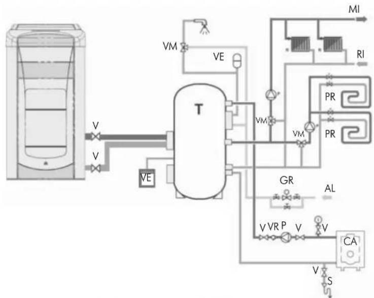
flowchart
graph TD
    A["Container"] -->|V| B["Tank"]
    B -->|VE| C["Valve"]
    B -->|VM| D["Pressure Valve"]
    D --> E["Control Valve"]
    E --> F["MI"]
    E --> G["RI"]
    E --> H["PR"]
    E --> I["PR"]
    B --> J["Valve P"]
    B --> K["Valve V"]
    B --> L["Valve V"]
    B --> M["Valve V"]
    B --> N["Valve V"]
    B --> O["Valve V"]
    B --> P["Valve V"]
    B --> Q["Valve V"]
    B --> R["Valve V"]
    B --> S["Valve V"]
    B --> T["Valve V"]
    B --> U["Valve V"]
    B --> V["Valve V"]
    B --> W["Valve V"]
    B --> X["Valve V"]
    B --> Y["Valve V"]
    B --> Z["Valve V"]
    B --> AA["Valve V"]
    B --> AB["Valve V"]
    B --> AC["Valve V"]
    B --> AD["Valve V"]
    B --> AE["Valve V"]
    B --> AF["Valve V"]
    B --> AG["Valve V"]
    B --> AH["Valve V"]
    B --> AI["Valve V"]
    B --> AJ["Valve V"]
    B --> AK["Valve V"]
    B --> AL["Valve V"]
    B --> AM["Valve V"]
    B --> AN["Valve V"]
    B --> AO["Valve V"]
    B --> AP["Valve V"]
    B --> AQ["Valve V"]
    B --> AR["Valve V"]
    B --> AS["Valve V"]
    B --> AT["Valve V"]
    B --> AU["Valve V"]
    B --> AV["Valve V"]
    B --> AW["Valve V"]
KEY
AL: Mains water supply system
CA: Boiler
GR: Filling Unit
M: Delivery to system
P: pump (circulator)
PR: Heating Panels
R: Radiators
RI: System Return
T: Heat Accumulator
V: Valve
VE: Expansion tank
VR: Check Valve
VM: Tempering Valve
VST: Thermal discharge valve
Heating and domestic hot water production system in combination with wall mounted boiler
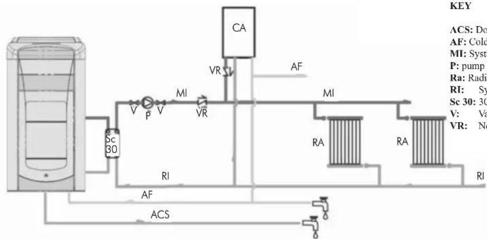
flowchart
graph TD
    A["Water Tank"] --> B["Valve"]
    B --> C["Pressure Valve V"]
    C --> D["MI Valve"]
    D --> E["Reservoir CV"]
    E --> F["Reservoir AV"]
    F --> G["Reservoir MI"]
    G --> H["Reservoir RA"]
    H --> I["Reservoir RA"]
    I --> J["Reservoir RI"]
    J --> K["Water Flow"]
    K --> L["ACS"]
    L --> M["Flow Path"]
    style A fill:#f9f,stroke:#333
    style B fill:#ccf,stroke:#333
    style C fill:#cfc,stroke:#333
    style D fill:#fcc,stroke:#333
    style E fill:#cff,stroke:#333
    style F fill:#ffc,stroke:#333
    style G fill:#fcf,stroke:#333
    style H fill:#cff,stroke:#333
    style I fill:#ffc,stroke:#333
    style J fill:#cfc,stroke:#333
    style K fill:#fcc,stroke:#333
    style L fill:#cfc,stroke:#333
    style M fill:#fcc,stroke:#333
    style N fill:#ffc,stroke:#333
    style O fill:#cfc,stroke:#333
    style P fill:#fcc,stroke:#333
    style Q fill:#cfc,stroke:#333
    style R fill:#fcc,stroke:#333
    style S fill:#cfc,stroke:#333
    style T fill:#fcc,stroke:#333
    style U fill:#cfc,stroke:#333
    style V fill:#fcc,stroke:#333
    style W fill:#cfc,stroke:#333
    style X fill:#fcc,stroke:#333
    style Y fill:#cfc,stroke:#333
    style Z fill:#fcc,stroke:#333
KEY
ACS: Domestic Hot Water
AF: Cold Water
MI: System delivery
P: pump (circulator)
Ra: Radiators
RI: System Return
Sc 30: 30 Plate Exchanger
V: Valve
VR: Non-return valve
NOTE:
The installer must assess the possible need for an additional expansion tank, depending on the type of system being serviced
WARNING:
during the production of domestic the power to the radiators decreases temporarily.
ACCESSORIES:
In the diagrams referred to in the previous pages the use of accessories available from the Edilkamin catalogue has been assumed.
Individual spare parts are also available (exchanger, valves, etc). For information, please contact your local dealer.
1. START UP (DEALER)
Make sure the plumbing system has been properly executed and is equipped with an expansion tank which is sufficient to guarantee safety. The presence of the tank built in to the stove does NOT guarantee adequate protection from thermal expansion experienced by the water inside the system.
Power on the stove electrically and run the test cold.
Carry out the filling of the system through the inlet valve (it is recommended that you maintain a pressure of approximately 1 bar) During the loading phase, "bleed" the pump and open the manual vent (see page 42)
This operation must also be performed subsequently on a periodic basis.
MOUNTING THE COVERING
QUEBEC - TORONTO - DETROIT - BOSTON
Phase 1: Representation of the stove after unpacking
N.B.: the Thermo-stoves come furnished with the ceramics packed in separate boxes in order to avoid damage during transport as well as to lighten and facilitate the manual handling of the product. The Ottawa/Atlanta Boiler has its steel front sides preassembled at the factory.
Phase 2: Mounting the ceramic lower front panel
Position the front panel on the lower portion of the door so that the to protruding portions on the back fit into the holes (A). Attach the front panel using the brackets (B) and screws supplied for this purpose, working from the back face of the small door (N.B.: the plates can be found in a small bag inside the hearth of the thermo-stove).
When opening the door, check whether it rubs against the ceramic sides of the covering.
(N.B.: if necessary, use the supplied trim between the ceramic front panel and the cast iron front panel in order to compensate for any in accuracies, which are typical of ceramics).
Phase 3: Mounting the ceramic upper front panel
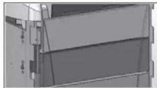
Remove the cast iron upper front panel (C) by pulling it forward to disengage it from the springs that hold it in place (hold the door open to facilitate the operation).
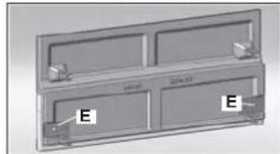
Apply the plates (E) to the rear of the upper front panel in ceramic and fastening them within the appropriate holes using the supplied self-threading screws. (N.B.: the plates can be found in a small bag inside the hearth of the thermo-stove).
Place the ceramic front panel in place so that the two protuberances at the back fit into the holes (D) on the cast iron front panel (C). Attach the ceramic front panel using the brackets (E) and supplied hexagon-head screws, working from the back face of the cast iron front panel. (N.B.: if necessary, use the supplied trim between the ceramic front panel and the cast iron front panel in order to compensate for any in accuracies, which are typical of ceramics).
Replace by fitting into the appropriate fastening clips.
Phase 4: Installation of ceramic side panels
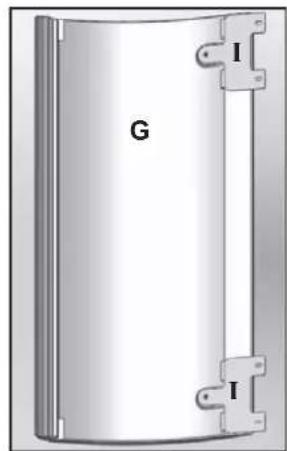
4/2. Apply the plates (I) to the rear of the ceramic side panels (large G and small H) and fastening them within the appropriate holes using the supplied screws (N.B.: the plates can be found in a small bag inside the hearth of the thermo-stove).
Disassemble the sheet metal half panels at the rear by removing their fastening screws (Refer to the letter P in the diagram shown below).
4/1. Mount the ceramic side panels (G and H) in the correct sequence small/large following these steps:
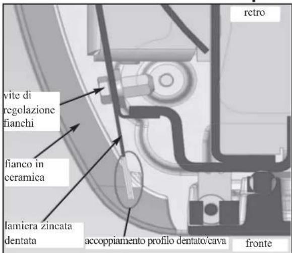
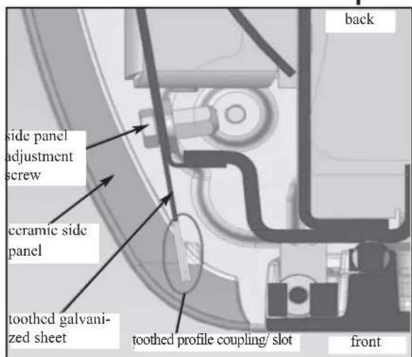
- Each element should be approached from the side and fitted into the slot (M - present along the front edge of the element itself) on the vertical toothed sheet metal profile of the structure.
4/1. Fasten the plates (I) applied, to the structure of the stove using the screws supplied in the appropriate holes (N).
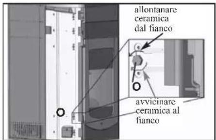
4/2. Adjust the couplings and the alignments using the appropriate adjustment screws (O); the adjustment screw is located below each ceramic element so it is therefore necessary to remove the elements in question one at a time in order to work on them.
-Replace the rear cast iron semi-side panels (Refer to the letter P in the diagram shown below)..
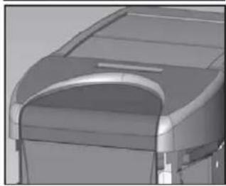
Phase 5: Mounting the ceramic top
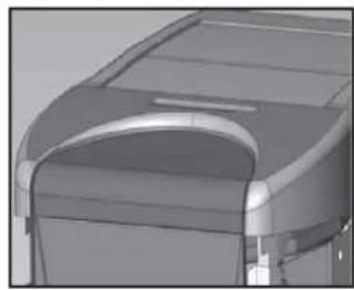
Place the ceramic top in its housing so that the protuberance at the back fits into the hole (P) in the cast iron top.
Phase1
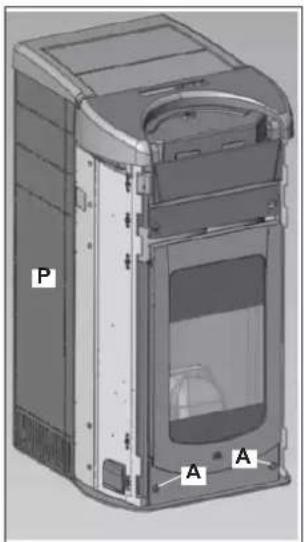
Phase 2 Mounting the lower front panel
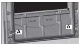
rear view of small door
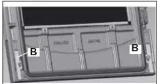
rear view of small door
natural_image
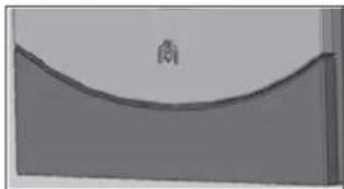
Simple 3D diagram of a curved surface with a small symbol inside, no text or labels presentfinished view
MOUNTING THE COVERING
Phase 3 Mounting upper front panel
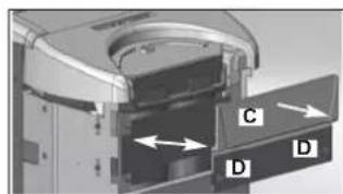
Front view of the cast iron front panel
natural_image
3D diagram of a rectangular device with four compartments and labeled ports (no text or symbols beyond labels)rear view of the cast iron front panel finished view
natural_image
Exterior view of a modern office building (no signage)finished view
Phase 5 mounting ceramic top
natural_image
3D mechanical assembly diagram showing a component with an arrow pointing to a central part (no text or symbols visible)fixing
natural_image
3D rendered mechanical component with curved and rectangular features (no visible text or symbols)finished view
Phase 4 mounting ceramic side panels
4/1

4/3

4/2
natural_image
Diagram of a cylindrical device with labeled components 'G' and 'I', no readable text or symbols beyond labels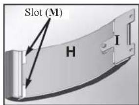
4/4

MOUNTING THE COVERING
MONTREAL - MIAMI
Photo 1: Representation of the stove after unpacking
N.B.: the Thermo-stoves come furnished with the ceramics packed in separate boxes in order to avoid damage during transport as well as to lighten and facilitate the manual handling of the product.
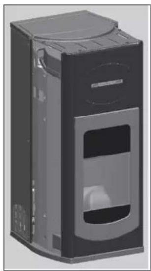
Installing ceramic tops
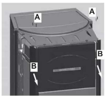
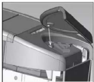
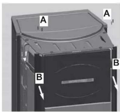
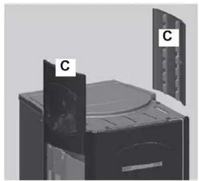
Remove the 4 pins (A) from the plating top and move the 2 aluminium sides (B) slightly forward.
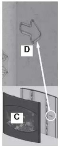
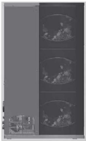
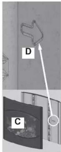
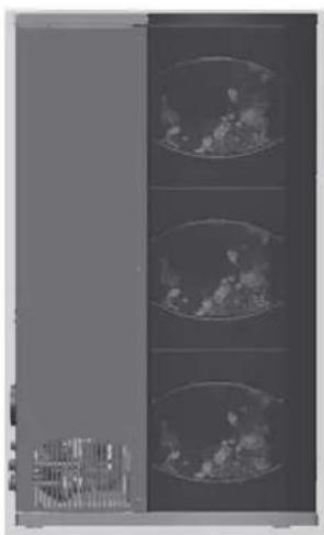
Put in the ceramic sides (C) in from the top downwards. On the inside of the ceramic sides there is an arrow (D) that indicates the side of the tile that must be towards the front of the stove (follow the views of the sides E and F).
Put the 2 aluminium sides back in position, fix the 4 pins removed before, and position the ceramic top (G).
Photo 1
natural_image
Exterior view of a black industrial device casing with ventilation grilles and a circular vent (no text or symbols visible)Installing ceramic tops
Left side view E
natural_image
3D rendering of a mechanical device with two labeled components (C), no visible text or symbols on the device itself.Right side view F
natural_image
Exterior view of a modern office building (no signage)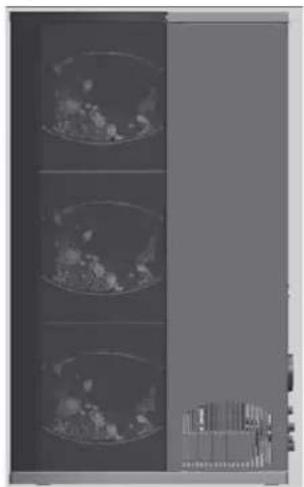
natural_image
Three vertical panels showing cross-sectional views of a medical or scientific instrument, with no visible text or symbols.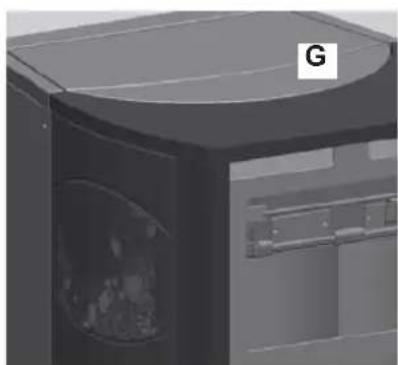
natural_image
3D rendering of a mechanical device with a labeled component 'G' (no text or symbols on the device itself)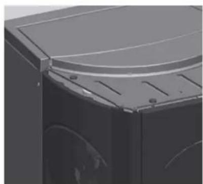
natural_image
Close-up of a black mechanical component with a curved top and side slots (no visible text or symbols)MOUNTING THE COVERING
QUEBEC / DETROIT
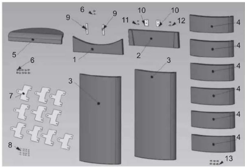
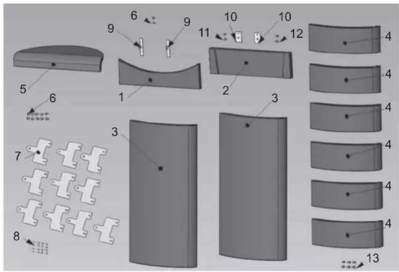
| n° ced. | |||
| 1 | Red lower front panel 1 642050 | ||
| 1 | Off-white lower front panel 1 642040 | ||
| 2 | Red upper front panel 1 642070 | ||
| 2 | Off-white lower front panel 1 642060 | ||
| 3 | Red large side panel | 2 642090 | |
| 3 | Off-white large side panel | 2 642080 | |
| 4 | Red small side panel | 6 46 60 | |
| 4 | Off-white small side panel | 6 645750 | |
| 5 | Red top 1 642130 | ||
| 5 | Off-white top 1 642120 | ||
| 6 | Screw T.B. 6x12 12 284380 | ||
| 7 | Piastrine ceramiche 10 647670 | ||
| 8 | Screw 4,8x10 16 266940 | ||
| 9 | Door ceramic blocking plate 2 387530 | ||
| 10 | Front ceramic blocking plate | 2 388890 | |
| 11 | Screw T.E. 6x16 | 2 18650 | |
| 12 | Screw 4,2x6,5 2 235990 | ||
| 13 | Spacer | 6 266670 | |
TORONTO / BOSTON
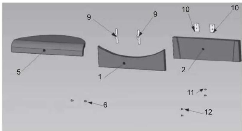
| pz | end. | ||
| 1 | Red lower front panel | 1 642050 | |
| 1 | Off-white lower front panel | 1 642040 | |
| 2 | Red upper front panel | 1 642070 | |
| 2 | Off-white lower front panel | 1 642060 | |
| 5 | Red top | 1 642130 | |
| 5 | Off-white top | 1 642120 | |
| 6 | Screw T.B. 6x12 | 2 284380 | |
| 9 | Door ceramic blocking plate | 2 387530 | |
| 10 | Front ceramic blocking plate | 2 388890 | |
| 11 | Screw T.E. 6x16 | 2 | 18650 |
| 12 | Screw 4,2x6,5 | 2 235990 | |
MONTREAL / MIAMI
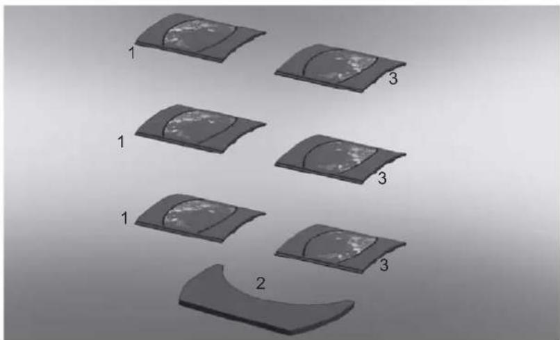
natural_image
Diagram showing six stages of a curved, segmented object with numbered labels (1, 2, 3, 1) — no text or symbols present.| pz | cod. | ||
| 1 | Right side | 3655220 | |
| 2 | Top | 1655210 | |
| 3 | Left side | 3657430 | |
INSTRUCTIONS FOR USE
Mimic panel

to turn on and off (hold down for 2") and to exit from the menu during programming

to access the menu during programming

to increase the various settings

to decrease the various settings

(pellet loading/reserve button)
press once to 'inform' the thermo-stoves memory that a 15 kg sack of pellets has been loaded, thereby allowing it to keep track of the reserve.

(boiler setting button)
this button together with the +/- keys controls a secondary circuit, e.g. that of a boiler.
The right side of the display shows the temperature of any external storage tank/boiler (if the boiler sensor is connected). Press the 'boiler' button to see the set value. If the boiler sensor is not connected, dashes will appear instead of the temperature (--- °C).
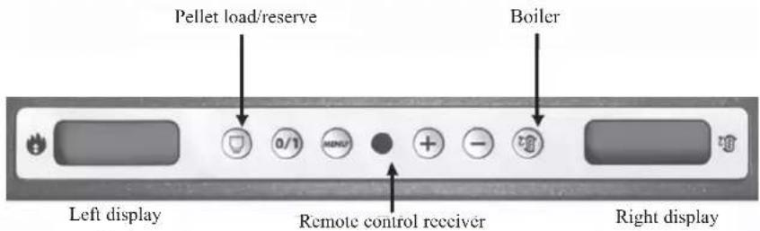
1st ignition
The first start up must, without fail, be performed by DEALER.
You must consult the DEALER in your area when igniting the stove for the first time, in order for the thermo-stoves to be calibrated according to the type of pellets and installation conditions
The DEALER must also:
- Verify that the hydraulic system is correctly installed and is equipped with an expansion tank that is sufficiently large to guarantee safety. The presence of a tank within the thermo-stoves does NOT guarantee appropriate protection from thermal expansion occurring in the whole system.
- Connect the electrical power to the thermo-stoves and implement a cold test (to be carried out by the DEALER).
- Fill the system using the filling tap (it is recommended not to exceed a pressure of 1bar).
When filling, 'bleed' the pump and the relief tap.
Warning:
During the initial start up phase, use the manual valves (V1-V2-V3) beneath the cast iron cover to perform the air/water purging operation. This operation must also be repeated during the first days of use and whenever the system is reloaded, even partially. The presence of air within the pipelines can hinder the unit's proper functionality. Rubber tubes are supplied with valves V1 and V2 to facilitate relief operations.
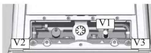
First ignitions.
There may be a slight smell of paint the first few times it is ignited, however, this will disappear quickly. Before igniting you must check:
- that installation is correct / • the power supply/ • that the door closes properly to a perfect seal
- that the combustion chamber is clean/ - that the display is on stand-by (time and temperature set).
INSTRUCTIONS FOR USE
Filling the feed screw
If the pellet storage tank is completely emptied, it follows that the Archimedes' screw is also emptied. Before restarting the stove you must fill it by following these steps: press the +/- keys simultaneously (via the radio control/ remote control or the synoptic panel) for a few seconds, after which, having released the keys, the display will show the text "Reload".
It is quite normal for some pellet residue to remain inside the hopper, this is what the feed screw is unable to pick up. Once a month, fully vacuum the hopper to prevent dusty residue from accumulating.
Automatic ignition
With the thermo-stoves on stand-by, press the 0/1 button for 2 seconds (on the synoptic panel or radio control/ remote control). This will start-up the ignition process, 'Start' will appear on the display and a countdown will commence in seconds (1020). There is no preset time for the ignition process: its duration will be automatically shortened if the control board detects that certain tests have been carried out positively. The flame appears after about 5 minutes.
Manual ignition (in case of start up failure)
At a temperature lower than 3 ^ – too low for the electrical resistance to become red hot - or if the resistance is temporarily not working, you can use a firelighter to ignite the thermo-stoves.
Insert a well-lit firelighter into the combustion chamber, close the door and press 0/1 on the synoptic panel or radio control/ remote control.
Operating modes
Operating from synoptic panel/radio control/ remote control. With the thermo-stoves running or on stand-by, from the synoptic panel: - press the + or - keys to increase or decrease the desired water temperature.
- by pressing the ⬤ key you can change the SET temperature of the boiler or of the secondary circuit in general, using the +/- keys. It is possible to visualise (if the boiler probe is connected) the temperature of any boiler/external storage, by pressing the "boiler" key the set value is displayed, by pressing the +/- keys while viewing the boiler value set that setting can be varied. If the boiler probe is not connected dashes appear in place of the temperature (--,-° C).
Shutdown
While the stove is working pressing the 0/1 key for 2 seconds begins the shutdown process and "OFF" is displayed (for 10 minutes).
The turning off phase includes:
-The interruption of falling pellets
-The circulation of running water.
Never pull the plug during shutdown.
N.B. Please note that the circulator runs until the water temperature drops below 40^ C.
Setting the clock
Press the MENU button for 2 seconds and use the + and - keys to follow the instructions given on the display to access the 'Clock' menu. This allows you to set the time on the electronic control board. Then press MENU and the following data appears in sequence - this can be adjusted: day, month, year, hour, minutes, day of the week. When 'Save?' appears on the display, you can check that the settings have been entered correctly before confirming. Press MENU to save the information ('Save OK' then appears on the display).
Programmer to ignite and shutdown the thermo-stoves at various times during the week.
Press the MENU button on the radio control/ remote control for 2 seconds to access the time setting function and press the + key to access the weekly timer function 'Program ON/OFF' will appear on the display.
The timer allows you to set a number of ignitions and shutdowns per day (up to a maximum of three), for each day of the week. As you confirm via the MENU button, one of the following options will appear:
- No Prog. (no program is set)
- Program/daily (a single program is set for every day)-
- Program/weekly (a program is set for each day of the week)
Move from one to the other using the + and - keys.
Use the MENU button to confirm the 'Daily program' option and access the selection of the number of programs (ignition/shutdown) to be set per day. Use the 'Program/daily' option to set the identical program/s for every day of the week.
The following will be displayed if the + key is pressed:
- No Prog.
- Prog. No. 1 (one ignition and one shutdown per day), Prog. No. 2 (same as before), Prog. No. 3 (same as before)
Use the button to show them in reverse order. If the 1st program is selected, the ignition time is shown.
The display shows: 1 Ignition Hour 10.30; use the +/- keys to change the hour and press MENU to confirm.
The display shows: 1 Ignition Minutes 10.30; use the +/- keys to change the minutes and press MENU to confirm. In the same way, adjust the shutdown times.
The program is confirmed by pressing the MENU button when "Saved" appears on the display.
When confirming 'Program/week', you will need to choose the day to which the program is to apply:
INSTRUCTIONS FOR USE
1 Mon; 2 Tues; 3 Wed; 4 Thurs; 5 Fri; 6 Sat; 7 Sun
Once you have chosen the day by scrolling through them with the + and - keys, confirm by pressing MENU and proceed with the settings of the programs in the same way as for the 'Program/daily', selecting whether or not to enable a program for each day of the week and choosing the number and times of interventions.
Should you make a mistake whilst setting the programs you can exit without saving by pressing the 0/1 key and 'Saved' will appear on the display.
Should the hopper run out of pellets, the stove will block and 'Stop Flame' will appear.
Pellet reserve warning
The thermal stoves are equipped with an electronic pellet detection system.
The pellet detection system is integrated into the electronic control board, allowing the stove to monitor how many kilos of pellets are left. This verification is implemented at any point whilst the stove is in operation mode.
For correct system operation, it is important that the following procedure is adhered with during the first ignition (that must be implemented by the DEALER). Before starting to use the pellet detection system, you must load and consume a full sack of pellets.
This allows for a brief running-in of the loading system.
Subsequently load 15 kg of pellets.
Then press the 'reserve' button once, thereby storing the data into the memory that 15 kg have been loaded.
From now on the display will show the remaining pellets as they decrease in kg (15...14...13). Each time pellets are reloaded you must enter the quantity. E.g. when loading 15 kg, simply press the 'pellet load' button to enter this into the memory.
For other quantities, or in the event of an error, you can specify the quantity using the pellet reserve menu as follows:
Press the MENU button for 2 seconds to view the SETTINGS. Press + or - consecutively to view T. Max exit.
Confirm by pressing MENU and the remaining quantity of pellets will be displayed + that being loaded (default is 15 and can be changed using the +/- keys). Should the hopper run out of pellets, the stove will block and 'Stop/Flame' will appear.
Tb = puffer temperature
TM = outlet temperature
P2 TM 1 (9°...) = working power and outlet temperature during the functioning
P3 TM1 (9°...) = working power and outlet temperature during the functioning
P4 TM 1 (20°...) = working power and outlet temperature during the functioning
P5 TM ... = working power and outlet temperature during the functioning
P6 TM... = working power and outlet temperature during the functioning
P7 TM...(26°...) = working power and outlet temperature during the functioning
Tb ___.° = puffer temperature during the functioning
Set = outlet temperature set
Economy Off = boiler turn off for the Economy mode
ON = ignition phase
Economy On. = boiler turn on for the Economy mode
Economy Warmup. = boler during the warm up phase after the ignition in the Economy mode
Melting pot cleaning = melting pot cleaning phase
Pell. Kg UTE 307 = quantity of bourned pellet after the last customer reset
Economy Wait. = the boiler are waiting the next ignition for the Economy mode
Program ON/OFF. = Possibility to use the daily or weekly program
ADJ pellet = adjustment of pellet for the technical assistance center EDILKAMIN
Radio Menu = radio remote control menu for the technical assistance center EDILKAMIN
Radio Channel 84 = radio remote control settings for the technical assistance center EDILKAMIN
FIRM. 22 10.03.03 = factory use descriptions, not consider
AIR _ - °C = room temperature read by remote control
Auto set = room temperature set get by remote control
Menù test I/O = used by the technical assistance center EDILKAMIN
Test pa = draft check during the ignition phase
Power RF max 6 = maximum radio frequency power, factory use
When the boiler receive current will sound 2 times, the first one briefly and the second one a long sound = boiler is ready to work
Kg 87 H11 = motherboard theoretical calculation of remaining pellet in the boiler tank and the and the working hour at the functioning power
INSTRUCTIONS FOR USE
RADIO CONTROL (OTTAWA / ATLANTA)
This controls all the functions.
For further information contact our customer service centre.
Key to buttons and display:

: to turn off and on (to go from remote control on stand-by to radio control on)
+/-
: to increase/decrease the various regulations
A
: to select function
M : to access the control and programming menus
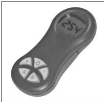
natural_image
Close-up of a gray handheld device with a numeric display showing '254' and control buttons (A, B, C, D) on its body.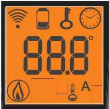

- icon flashing: radio control searching for network
- icon fixed: radio control with connection enabled

flat battery
(press "A" and "M" in parallel for a few seconds to lock or unlock the keypad)

programming enabled

alphanumeric display consisting of 16 figures arranged in two lines of 8 figures
- icon flashing: thermo-stoves turning on
- icon fixed: thermo-stoves working


automatic function (display shows temperature)
The display also shows other useful information in addition to the icons described above.
Stand-by Position:
shows the set water temperature (Set 70°C), the flow temperature (Tm 65°C), the kg of pellets remaining (15 kg) in the tank and the current time (15:33)
- Automatic operating phase:
shows the set water temperature (Set 70°C), the flow temperature (Tm 65°C), the kg and remaining autonomy (50KG 10H) and the current time (15:33)
Press button "A" on the radio control unit to switch from the classic "Power_Module" mode to "Comfort_Climate" mode.
In "Comfort_Climate" mode, press the +/- button on the radio control unit's synoptic panel to set the desired room temperature. The following situations, for example, will occur:
-With a room temperature below the setting, the thermo-stoves will modulate the power levels normally in order to pursue the output set. -If the room temperature has been reached, the thermo-stoves will set its power to P1.
-The temperature is transmitted from the supplied radio control, which must be within range of the radio field (unobstructed linear distance of 15 m).
- In the event that the connection between the radio control unit and the stove should be lost, the thermo-stove will continue its working phase at the P1 power level.
n alternate temperature monitoring system is available. In fact, it is possible to connect an external room thermometer (readily available on the market) to the serial port:
The thermo-stoves will automatically recognise the thermostat's connection to the serial port and, as a result, one of the following situations will occur:
-With a room temperature below the external thermostat's setting, the stove will modulate the power levels normally in order to pursue the output set.
-If the external thermostat's room temperature has been reached, the thermo-stoves will set its power to P1.
- An asterisk on the display indicates that the external thermostat is requesting for the rooms to be heated.
INSTRUCTIONS FOR USE
Clock regulation
Press and hold the key "M" for 2 seconds to access the "CLOCK" menu. This allows you to set the internal electronic board clock.
By then pressing the key "M", the following data appears in sequence and can be regulated:
day, month, year, hour, minutes, day of the week.
The wording “SAVE?” will appear for confirmation with "M". This will allow you to check that the operations performed are correct, prior to completion (the wording “SAVE” will then be shown on the display).
Weekly timer
Press and hold the "M" key on the remote control for 2 seconds. This turns on the clock regulation and by pressing the '+' key, the weekly timer function is accessed, with the display showing the description "PROGRAMM ON/OFF". This function allows you to set a number of times the insert turns on and off per day (up to a maximum of three), each day of the week.
As you confirm the display with the key "M", one of the following options will appear:
NO PROG. (no programme set)
DAILY PROGRAM (single programme for every day of the week)
WEEKLY PROGRAM. (specific programme for each day individually)
Use the “+” and “−” keys to switch between programmes.
Use key "M" to confirm the option "DAILY PROGRAM" to choose the number of programmes (turn on/off) to be carried out per day.
Use the "DAILY PROGRAM" to set identical programme/s for every day of the week.
By then pressing the “+” key, the following can be seen:
- Prog. no.
- 1st prog. (one turn on and one turn off per day), 2nd prog. (identical), 3rd prog. (identical)
Use the “-” key to show in reverse order.
If the 1st programme is selected, the turn on time is shown.
The display shows: 1 "ON" at 10 Use the "+" and "-" key to change the hour. Confirm with the "M" key.
The display shows: 1 "ON" at 30 Use the "+" and "-" key to change the minutes. Confirm with the "M" key.
The same applies for the turn-off time to be set and for subsequent turning on and off.
Confirm by pressing "M" and the wording "SAVE??" will appear on the display.y.
When confirming "WEEKLY PROGRAM", you will need to choose the day to which the programming is to apply:
1 Mon ; 2 Tues; 3 Wed; 4 Thurs; 5 Fri; 6 Sa; 7 Sat
Once you have chosen the day, use the "+" and "-" key and confirm with the "M" key, to programme in the same way as for the "DAILY PROGRAM", choosing whether or not to enable a programme for each day of the week, and if so choosing number of interventions and at what times. Should you make an error during programming, you can leave the programme without saving. As you press a key, display will show the word "NO SAVE".
Variation feeding pellets (ONLY AFTER SUGGESTED BY DEALER)
Press and hold the "M" key on the remote control for two seconds. Scroll through the display instructions using the "+" and "-" keys, to the description "ADJ-PELLET". By confirming this function using the menu key you can adjust the supply of pellets, by reducing the set value, you decrease the supply of pellets, increasing the set value increases the supply of pellets. This function can be useful in the event that one changes the type of pellets used, no longer using those for which the stove was calibrated, thus necessitating an adjustment of the load setting.
Should this correction not suffice, contact the Edilkamin-authorised Dealer, to establish the new operating axis.
Notes on flame variability: Any changes in the state of the flame depend on the type of pellets used, as well as on normal variation of solid fuel flames and on the periodic cleaning of the crucible the stove automatically carries out (Note: This does NOT replace the necessity cold vacuuming by the user prior to start up).
LOW BATTERY INDICATOR

When the battery icon lights up it indicates that the batteries inside the radio control are almost flat. Replace them with three new batteries of the same model (size AAA 1.5V).
- Do not use new batteries with used ones.
- Do not mix brands and different types as every type and brand has a different capacity.
- Do not mix traditional batteries with rechargeable ones;
- Do not try recharging alkaline and zinc-carbon batteries as this can cause them to break and/or a liquid leakage.
INFORMATION FOR USERS
In accordance with Art. 13 of the Legislative Decree No. 151, dated 25 July 2005, "Implementation of Directives: 2002/95/EC, 2002/96/EC and 2003/108/EC, pertaining to the reduction of hazardous substances used in electrical and electronic equipment, as well as disposal of waste".
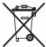
The crossed-out wheeled bin symbol shown on the equipment or on the packaging indicates that the product must be disposed of separately at the end of its useful life. Therefore, at the end of the equipment's useful life, the user must hand in the equipment to suitable collection facilities for electrical and electronic waste, or return it to the retailer when a new, equivalent appliance is purchased in a ratio of one to one.
INSTRUCTIONS FOR USE
REMOTE CONTROL (QUEBEC/TORONTO/MONTREAL/DETROIT/BOSTON/MIAMI)
This controls all the functions. It is necessary to point it directly at the thermo stove.
For further information contact our customer service centre.
Key to buttons and display:

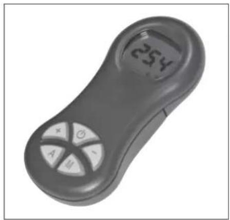
: ignition / shutdown button (press for approximately 1 second) this button can also be pressed to exit the programming menu
+ : button to increase the power/operating temperature (when inside a menu, it increases the displayed variable)
- : button to decrease the power/operating temperature (when inside a menu, it decreases the displayed variable)
A : button to switch to the "EASY TIMER" program
M : key for viewing/setting the set temperature (Set 70°C) and the kg of consumed pellets (Pellt KG. UTE 200)
natural_image
Close-up of a handheld electronic device with a display showing '254' and control buttons (no readable text beyond basic symbols)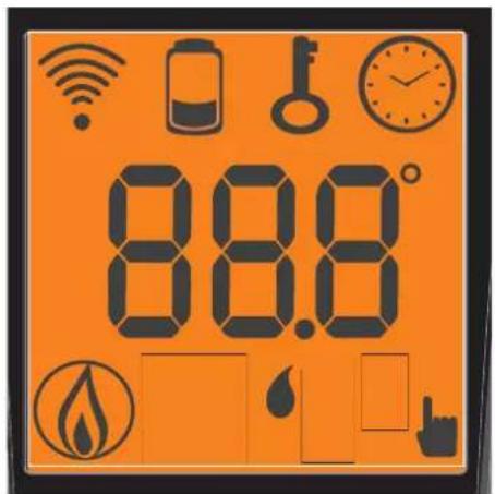

Indicates data transmission between the remote control and the control board.

low batteries; replace them and put them in their appropriate containers.

blocked keypad; avoid turning on the remote control for no reason (press "A" and "M" simultaneously for a few seconds to block/unblock the keypad)

Indicates that ignition / shutdown is being via the "EASY TIMER" program
Indicates the room temperature detected by the remote control (it indicates the values of the set parameters during its technical set-up).

On icon: thermo stove in start-up/operating phase

Indicates that the flow temperature can be set manually

pellet/water thermo-stoves remote control setting indicator
INSTRUCTIONS FOR USE
USING THE "EASY TIMER" PROGRAM

The new remote control allows you to manage a new timer program that is very intuitive and easy to use:
- If the thermo-stoves is on: a delayed shutdown can be set from the remote control - from one to twelve hours. The remaining time for the scheduled shutdown is shown on the display of the synoptic panel.
- If the thermo-stoves is off: a delayed ignition can be set from the remote control - from one to twelve hours. The remaining time for the scheduled ignition is shown on the display of the synoptic panel.
- Setting: proceed as follows to set the timer:
a) Press the "A" button and the icon will light up on the display, thereby confirming the "Easy timer" program has been accessed. b) Set the hours by pressing the +/- buttons, for example:

c) Point the remote control towards the synoptic panel receiver
d) Confirm the setting by pressing the "A" button for a few seconds; the icon will go off and the remaining time will appear on the synoptic panel after which the "Easy timer" setting will intervene. e) Repeat points a), b), c), d) to cancel the setting, and set the hours to "00H"
BLOCKED KEYPAD

The remote control buttons can be blocked so as to prevent it from going on accidentally.
Press the A and M buttons simultaneously and the key symbol 📁 will light up confirming that the keys have been blocked. Press the A and M buttons simultaneously once again to unblock the keypad.
LOW BATTERY INDICATOR

When the battery icon lights up it indicates that the batteries inside the remote control are almost flat. Replace them with three new batteries of the same model (size AAA 1.5V).
- Do not use new batteries with used ones.
- Do not mix brands and different types as every type and brand has a different capacity.
- Do not mix traditional batteries with rechargeable ones;
- Do not try recharging alkaline and zinc-carbon batteries as this can cause them to break and/or a liquid leakage.
INFORMATION FOR USERS
In accordance with Art. 13 of the Legislative Decree No. 151, dated 25 July 2005, "Implementation of Directives: 2002/95/EC, 2002/96/EC and 2003/108/EC, pertaining to the reduction of hazardous substances used in electrical and electronic equipment, as well as disposal of waste". The crossed-out wheeled bin symbol shown on the equipment or on the packaging indicates that the product must be disposed of separately at the end of its useful life. Therefore, at the end of the equipment's useful life, the user must hand in the equipment to suitable collection facilities for electrical and electronic waste, or return it to the retailer when a new, equivalent appliance is purchased in a ratio of one to one.
MAINTENANCE
Should ignition fail, DO NOT re-ignite until you have emptied the combustion chamber.
Regular maintenance is required for the thermo-stoves to function correctly.
The thermo-stoves will trigger the message: ‘smoke °C/high’ or ‘Mainten.’ to appear on the panel when further cleaning is necessary.
FAILURE TO PERFORM at least SEASONAL MAINTENANCE can cause the thermo-stoves to malfunction and any problems deriving from this will not be covered by the warranty.
Non-compliance with maintenance procedures will render the warranty null and void.
Before performing any maintenance, disconnect the appliance from the mains.
Weekly cleaning (see illustration on next page)
Cleaning should be carried out with the aid of a vacuum cleaner (see optional page. 53).
Operation to be carried out when the stove is cold.
Never vacuum hot ashes, as this would damage your vacuum cleaner.
• Vacuum the door and if necessary clean the glass (cold)
- Open the small door and remove and empty the ash tray (Fig. A-1) vacuum the fire bed.
- Remove the front tile (Fig. B-2).
- Vacuum the crucible or scrape it with the spatula provided, clear any obstructions from the holes on all sides, after removing the front plate (fig. C -3).
- Clean the spark plug
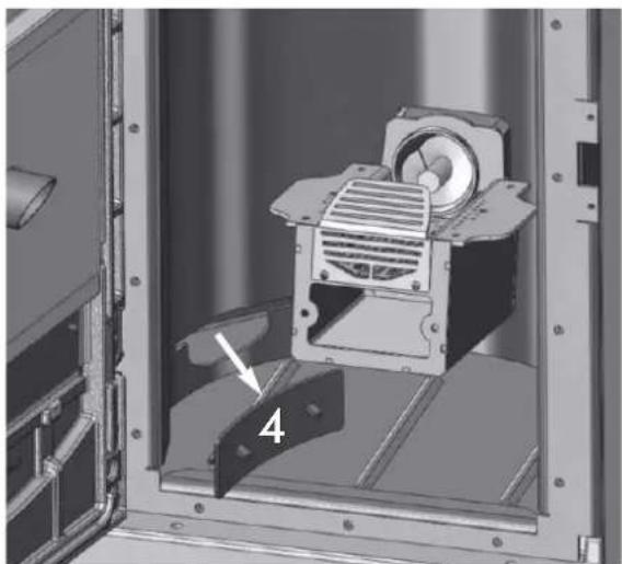
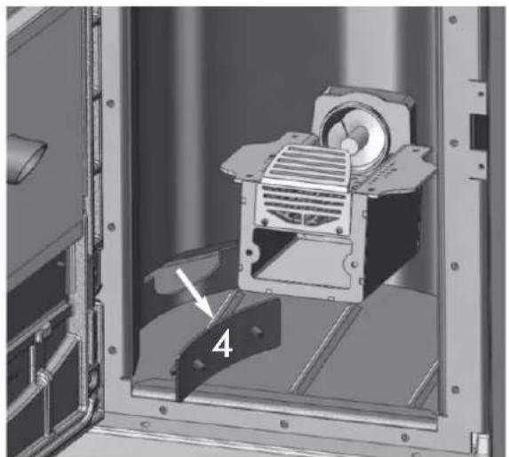
- Remove the inspection plugs on both sides of the hearth and vacuum the crucible (Fig. D-4).
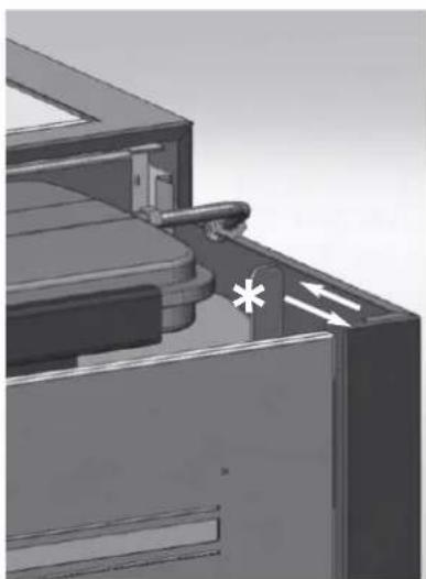
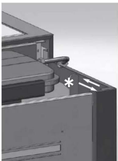
- Move the cleaning rods (^*) :
- For the Quebec/Toronto models, remove the ceramic top and make movements with the lever (see fig. E).
- For the Ottawa model, remove the metal top and make movements with the lever (see fig. F).
- For the Montreal/Miami models, open the top door and act on the lever (see fig. G).
- Following a period in which the stove has been inactive and in any case at least every month, empty the pellet storage tank and vacuum the bottom.
We remind you that using the stove without cleaning the melting pot, may cause a sudden ignition gas inside the combustion chamber with the consequent breaking of the glass
NOTE: The DEALER, upon commissioning, sets the kg value of consumed pellets; after which, the message "SERVICE UTE" will appear on the display. The thermo stove continues operation, but the end client is invited to perform careful maintenance, described above and explained by the DEALER during commissioning, to the extent of his abilities. To eliminate the message from the display, press the boiler button for at least 5 seconds after having completed maintenance.
Seasonal cleaning (implemented by the dealer)
The DEALER, upon commissioning, sets the kg value of consumed pellets; after which, the message "Mainten." will appear on the display. The thermo stove continues operation, but the end client must contact the DEALER to perform necessary seasonal maintenance. The end client is invited to perform seasonal maintenance regardless of which messages may appear on the display.
Before performing any maintenance, disconnect the appliance from the mains.
The Dealer will provide you, on the occasion of the first start up, with the stove maintenance book, where the steps for seasonal cleaning, outlined here below, are listed.
- Clean the thermo-stoves internally and externally
- Carefully clean the heat exchange tubes
- Carefully clean and remove dirt from the combustion chamber and the relative compartment
- Clean the motors, verify mechanical and clam loosening
- Clean smoke channel (replace seals on pipes) and smoke extraction fan chamber
- Check the expansion tank
- Check and clean the circulator
- Check the sensors
- Check and if necessary replace the clock battery on the control board
- Clean, inspect and scrape any residue from the ignition resistance compartment and if necessary, replace it
- Clean/check the Synoptic Panel
- Visually inspect the electrical wires, connections and power cable
- Clean the pellet hopper and check loosening of the feed screw - gear motor assembly
- Check and if necessary replace the door seal
- Functionality test: load the feed screw, ignite, let it run for 10 minutes and shutdown
If maintenance if not implemented, the warranty will be rendered null and void.
If the thermo-stoves is used very often, it is recommended to clean the smoke channel every 3 months.
When maintenance is implemented in the smoke channel, consider UNI 10847/2000 Individual chimney installations for generators running on liquid and solid fuel. Maintenance and control.
The chimney stacks and smoke ducts to which solid fuel appliances are connected should be cleaned once a year (verify whether in there are regulations in force in your country regarding this)
In the even that regular checks and cleaning are not performed the probability of a chimney fire increases.
In the event of such an occurrence proceed as follows: do not extinguish with water; empty the pellet storage tank; contact the Dealer before re-starting after such an incident.
MAINTENANCE
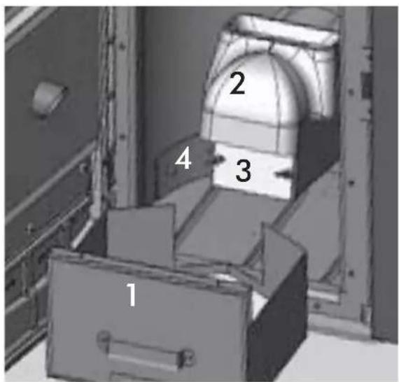
fig. A
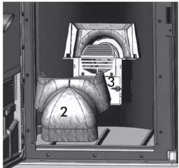
fig. B
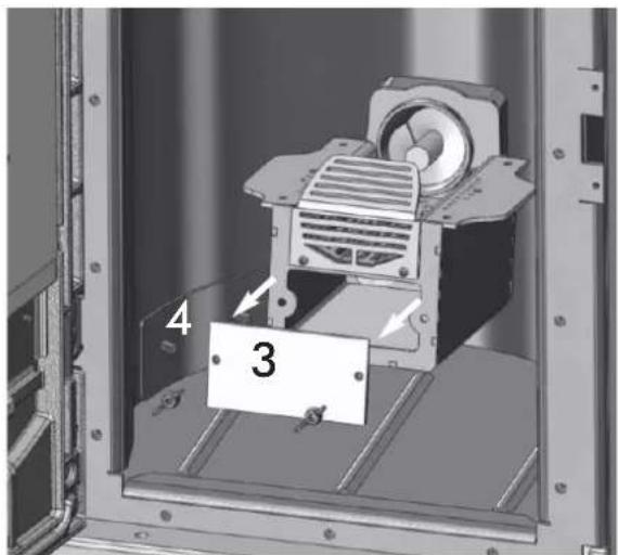
fig. C fig. D
natural_image
Mechanical assembly inside a metal enclosure, showing a motor and housing with a labeled component '4' (no text or symbols beyond label)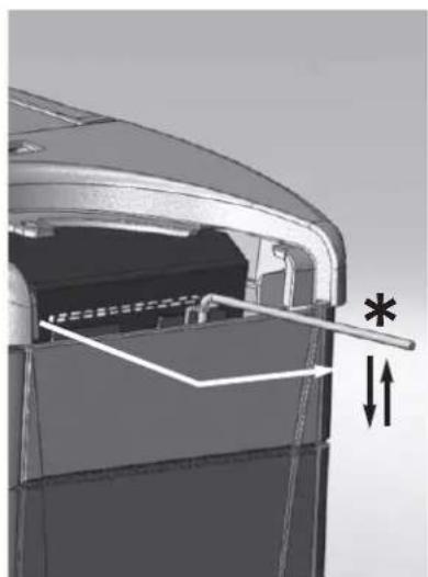
natural_image
Technical diagram of a mechanical component with internal structure and dimension arrows (no text or symbols)fig. E fig. F
natural_image
3D mechanical component diagram showing internal structure with arrows and a star symbol (no text or labels)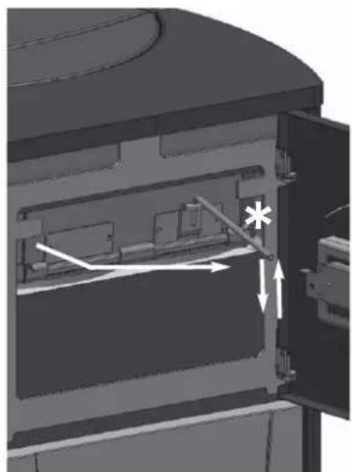
natural_image
3D mechanical assembly diagram showing internal components and directional arrows (no text or symbols)fig. G
POSSIBLE TROUBLESHOOTING
In the event of problems the thermo-stoves stops automatically and runs the shutdown process and the display shows text regarding the motivation of the shutdown (see the various alarms below).
Never pull the plug during shutdown on account of malfunction.
If the event of malfunction, to restart the thermo-stoves it is necessary to let the shutdown procedure proceed (10 minutes with acoustic signalling) and then press the 0/1 key on the synoptic panel.
Do not turn the stove on again before checking the cause of the malfunction and CLEANING/ EMPTYING the crucible.
INDICATION OF POSSIBLE CAUSES OF MALFUNCTION AND INDICATIONS AND REMEDIES:
1) H2O PTC_FAULT: Shuts down due to the water temperature sensor being broken or disconnected.
Check connection of the sensor to the control board. Verify functionality by means of a cold test
2) Verific./extract.: Shuts down due to the revolution sensor of the smoke extractor motor detecting an anomaly.
- Check smoke extractor functionality (connection of the revolution sensor)
- Check smoke channel for dirt
3) Stop/Flame: Shuts down due to a drop in smoke temperature (intervenes if the thermocouple detects a smoke temperature that is lower than that which is set, thereby interpreting it as a flame failure).
The flame may not go on for the following reasons:
- lack of pellets
- too many pellets in the combustion chamber have suffocated the flame
- the maximum thermostat / pressure switch / water safety thermostat has intervened to 'stop' the gear motor
4) Block_FI/NO Start: Shuts down due to incorrect smoke temperature during ignition (intervenes if the flame fails to appear within a maximum of 15 minutes, or if the ignition temperature is not reached).
Distinguish either of the following cases:
| The flame has NOT appeared | The flame has appeared but after Ignition appears on the display, “Block_FI/NO Start” appears |
| Verify:- positioning and cleanliness of combustion chamber- resistance functionality- room temperature; if lower than 3 °C a fire lighter is needed | Ask the DEALER to check:- thermocouple functionality- set parameters for ignition temperature |
5) Failure/Power: Shuts down due to an electricity failure (not a defect of the thermo-stoves).
Check electricity connection and drops in voltage.
6) Fault/RC: Shuts down due to a failure occurring in the thermocouple or it being disconnected
Verify connection of thermocouple to the control board. Verify functionality in a cold test.
7) smoke °C/high: Shuts down due to excessive smoke temperature
An excessive smoke temperature may occur because of the following: unsuitable pellet type, anomaly in smoke extraction, blocked smoke channel, incorrect installation, gear motor 'drift'.
8) H2O TEMP ALARM: Shuts down due to water temperature being higher than 90 °C.
An excessive temperature may occur because of the following:
- system too small: ask the DEALER to activate the ECO function
- blockage: clean the exchanger pipes, the combustion chamber and the smoke outlet.
9) Verific./Air Flow: (activates if the pressure sensor (vacuum gauge) detects insufficient values)
The vacuum may be insufficient in the event of an open door:
- imperfect door sealing (i.e. gaskets) / - problems with air suction or smoke expulsion/ - clogged chimney flue
- vacuum gauge reading point dirty with soot (clean with dry air).
Check calibration. Request DEALER assistance with parameters. The alarm may also be set off during the start-up phase.
Pascal value higher than the "AC max PA" threshold, displayed only for 2" without the blockage phase being activated.
11) STOP T/ SCREW 1:
Auger 1 turns when it should be still, probable motor control triac malfunction/wiring connection error.
12) STOP G/SCREW 1: (intervenes when the gear motor 1 is blocked or malfunctioning)
Check the wiring of the gear motor 1 or else replace it.
POSSIBLE TROUBLESHOOTING
13) STOP G/SCREW 2: (intervenes when the gear motor 2 is blocked or malfunctioning)
Check the wiring of the gear motor 2 or else replace it
14) Battery check:
The thermo-stoves does not stop but the error appears on the display. The buffer battery of the control board needs changing. Faulty contact with the clock's battery.
15) WARMING LOADER 2:
The sensor connected to auger 2 has detected a temperature which is superior to the threshold of the "LOAD 2 °C max" parameter. Probably too much Pellet in the melting pot, near to the secondary screw. Clean the melting pot more often.
Auger temperature sensor 2 malfunctioning or disconnected.
17) The pellet DOES NOT enter the crucible:
- The feed screw is empty:fill the feed screw by pressing the + and - keys simultaneously.
- The pellets are blocked in the hopper: use a vacuum cleaner to empty the pellet hopper.
- The gear motor is broken (an error is displayed on the synoptic panel).
- The feed screw safety thermostat ‘disconnects’ the electrical supply of the gear motor: check that it has not overheated. Use a tester or a temporary bridge to verify.
- The water overheating safety thermostat ‘disconnects’ the electrical supply of the gear motor: check that the thermo-stoves contains water. After having removed the protective cap, press the button on the back of the thermo-stove* to reset.
• In these cases, you MUST contact the DEALER before re-igniting.
Warnings are shown until you intervene and press the 0/1
key on the control panel. It is recommended not to use the thermo-stoves before verifying that the problem has been resolved.
It is important for the DEALER to know what warning signal appears on the panel.
18) synoptic panel is off:
- check the power cable connection,
- check fuse (on power cable),
- check connection of flat cable to synoptic panel
19) Radio control / Remote control not working:
- move closer to the thermo-stoves
- check the battery and if necessary, replace it
- extract the reclining antenna (OTTAWA/ATLANTA) ^*
20) Water is not hot enough:
- clean the hearth exchanger
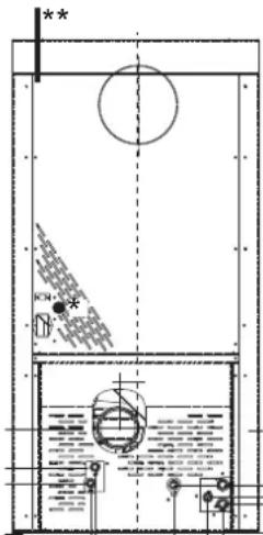
CHECK LIST
Positioning and installation
- Room ventilation
- Only the thermo-stoves outlet passes through the smoke channel/chimney flue
- The smoke channel has: a maximum of 2 curves – a maximum of 2 horizontal metres, at least 1.5 vertical metres
- The exhaust pipes are made of suitable material (recommended: stainless steel)
- When using any flammable materials (e.g. wood), all precautions have been taken to prevent a fire hazard
- The heating capacity has been appropriately assessed considering radiator efficiency: how many kW have been estimated to be necessary???
• The hydraulic system has been declared to be compliant with the Ministerial Decree 37 ex Law No. 46/90 by a qualified technician.
Use
- Good quality, dry wood pellets are used (diameter 6 mm) (maximum permissible humidity 8%).
The chimney pot and ash compartment are clean and well positioned.
• The cleaning rods are moved every day. - The exchanger tubes and internal parts of the hearth are clean.
• o The smoke extract duct (see page 34) is clean. - The bleeding process has been applied to the hydraulic system.
• The pressure (read on manometer) is approx. 1 bar.
FAQ
The answers are listed below in summary form, for further details see the other pages of this document.
1) What do I need to prepare in order to install the thermal stoves?
Smoke outlet that is at least 100 mm in diameter.
An air inlet in the room that is at least 80 cm ^4 .
^3/_4 " G outlet and inlet fitting.
^3/_4 G drains connection for overpressure valve.
34 " G load fitting.
A certified electrical connection with a thermal magnetothermic switch 230V +/- 10% 50 Hz.
(assess the division of primary and secondary circuits).
2) Can the thermo-stoves work without water?
NO. Using the thermo-stoves without water will damage it.
3) Do thermal stoves emit hot air?
NO. Most of the heat is transferred to the water.
Only Quebec / Toronto / Montreal / Detroit / Boston / Miami emit a small amount in the installation environment in the form of radiation from the glass hearth. It is advisable in any case to use a radiator in the same room.
4) Can I connect the inlet and outlet of the thermo-stoves directly to a radiator?
NO, just like other boilers, it must be connected to a collector from which the water is then distributed to the radiators.
5) Do thermal stoves also supply hot sanitary water?
It is possible to produce domestic hot water using the KIT built in to the stove, this is an instantaneous production without accumulation.
6) Can I discharge the smoke from the thermal stoves along the wall?
NO, a discharge which is conform with standards (UNI 10683) must reach the ridge of the roof, and in any case proper functioning requires a vertical stroke of at least 1.5 meters; avoiding that in case of power outage or wind, a slight amount of smoke forms in the installation environment.
7) Do I need an air inlet in the room where it is installed?
Yes, to replenish the air used by the thermo-stoves for combustion. The smoke extractor draws the air from the room into the combustion chamber.
8) What settings are required on the thermo-stoves display?
The desired water temperature. The thermo-stoves will then adjust the power accordingly to obtain or maintain this.
For small systems, a mode can be set that ignites and shuts down the thermo-stoves accordingly, as the water temperature is reached. (contact DEALER for initial start up)
9) Do I need to vacuum the pellet hopper?
Yes, at least once a month when the thermo-stoves is not used for some time.
10) Can I burn other fuel apart from pellets?
NO. The thermo-stoves has been designed to burn wood pellets that are 6 mm in diameter. Any other material can damage it.
11) Can I ignite the thermo-stoves by sending an SMS?
Yes, if the DEALER or an electrician has installed the connection via an optional cable code 640560 to the serial port behind the thermo-stoves
CLEANING ACCESSORIES (optional extras)
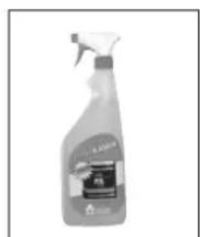
GlassKamin
(code 155240)
Used for cleaning the ceramic glass
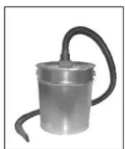
natural_image
Metal cylindrical device with black hose, no visible text or symbolsAsh vacuum cleaner
without motor
(code 275400)
User for cleaning the
hearth
Madame, Monsieur,
2006/95/CEE - Directive Basse Tension
natural_image
Technical line drawing of a cylindrical container with a side tab and height dimension labeled 126 (no text or symbols beyond measurement lines)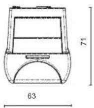
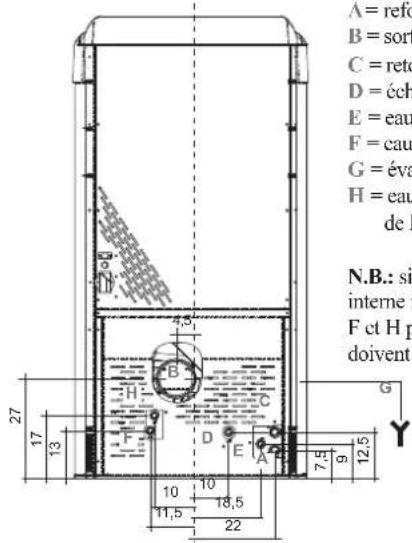
natural_image
Technical line drawing of a vertical panel with a horizontal dimension labeled 124 (no text or symbols beyond the label)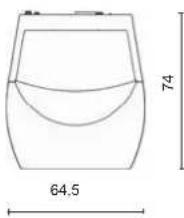
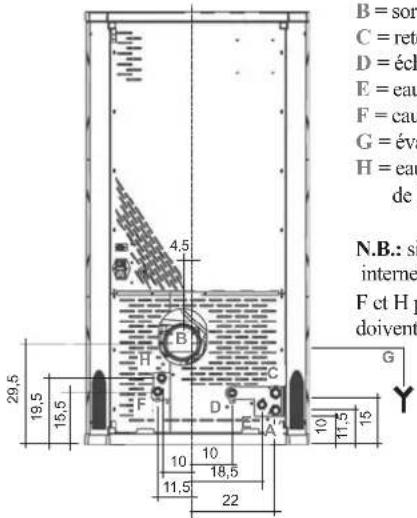
natural_image
Simple line drawing of a cabinet or enclosure with a door and side panel, no text or symbols present.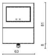
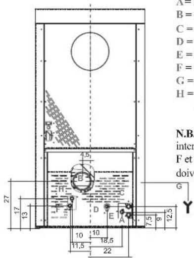
natural_image
Close-up of a small electronic component with wires and a metallic housing (no visible text or symbols)PORT SÉRIE
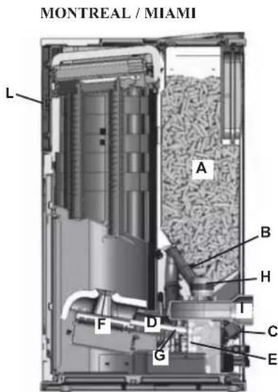
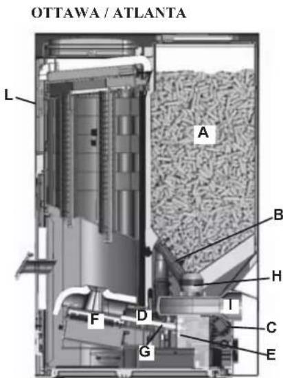
natural_image
Mechanical assembly diagram showing interconnected pipes and components (no visible text or labels)Circulateur
natural_image
Simple 3D diagram of a curved surface with a small symbol inside, no text or labels presentnatural_image
Mechanical assembly diagram showing a component with labeled parts C, D, and directional arrows (no text or symbols beyond labels)natural_image
Exterior view of a modern office building (no signage)natural_image
3D rendering of a mechanical device with an open lid and internal components (no visible text or symbols)fixation
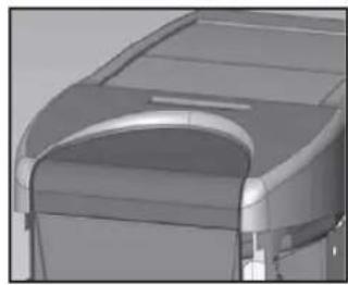
natural_image
3D rendered mechanical component with curved and rectangular features (no visible text or symbols)4/3
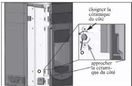
natural_image
Exterior view of a cylindrical metallic panel with labeled corners (G, I) and no additional text or symbols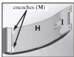
4/4
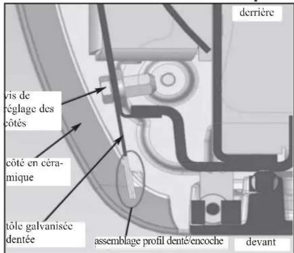
natural_image
Exterior view of a black industrial device casing with internal compartments (no visible text or symbols)natural_image
3D rendering of a mechanical device with two labeled components (C), no visible text or symbols on the device itself.vue flanc droit F
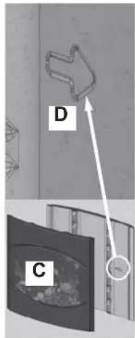
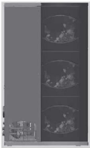
natural_image
Interior view of a server rack unit with three circular insets showing internal components (no visible text or labels)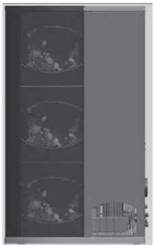
natural_image
Medical imaging scan showing three cross-sectional views of a patient's chest (no visible text or labels)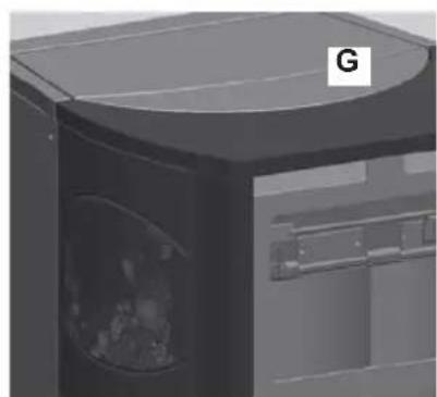
natural_image
3D rendering of a mechanical device with a curved top and internal cavity (no visible text or symbols)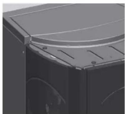
natural_image
Close-up of a metallic mechanical component with a curved top and internal cutouts (no visible text or symbols)MONTAGE REVÊTEMENT
QUEBEC / DETROIT
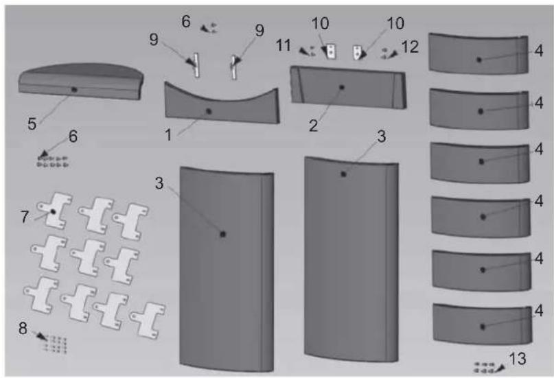
natural_image
Diagram showing six stages of a curved surface with three numbered regions, no text or symbols presentON = PHASE D'ALLUMAGE
Economy On. = CHAUDIÈRE RÉGLÉE EN FONCTIONNEMENT ECONOMY ALLUMÉE
Economy Warmup. = CHAUDIÈRE RÉGLÉE EN FONCTIONNEMENT ECONOMY EN PHASE DE STABILISATION APRÈS L'ALLUMAGE
Nettoyage creuset = PHASE AUTOMATIQUE DE NETTOYAGE DU CREUSET
Pell. Kg UTE 307 = CALCUL DU GRANULE UTILISÉ DEPUIS LA DERNIÈRE REMISE À ZÉRO DE LA PART DE L'UTILISATEUR
Economy Wait. = CHAUDIÈRE RÉGLÉE EN FONCTIONNEMENT ECONOMY EN ATTENTE DE RALLUMAGE
Program ON/OFF. = POSSIBILITÉ DE PROGRAMMATION HORAIRE JOURNALIERE OU HEBDOMADAIRE
ADJ pellet = RÉGLAGE DU GRANULÉ À USAGE EXCLUSIF DU TECHNICIEN EDILKAMIN
Menu' Radio = RÉGLAGES MENU RADIOCOMMANDE À USAGE EXCLUSIF DU TECHNICIEN EDILKAMIN
Canal radio 84 = RÉGLAGES MENU RADIOCOMMANDE À USAGE EXCLUSIF DU TECHNICIEN EDILKAMIN
FIRM. 22 10.03.03 = DESCRIPTIONS À USAGE DE L'ENTREPRISE, NE PAS TENIR COMPTE
AIR ____ °C = RÉGLAGE TEMPÉRATURE AIR DÉSIRÉE DANS LA PIÈCE, LUE PAR LA RADIOCOMMANDE
Auto set = POSSIBILITÉ DE RÉGLAGE TEMPÉRATURE AIR DÉSIRÉE DANS LA PIÈCE, LUE PAR LA RADIOCOMMANDE
Menù test I/O = À USAGE EXCLUSIF DU TECHNICIEN EDILKAMIN
Test pa = TEST TIRAGE INITIAL À L'ALLUMAGE
Power RF max 6 = PUISSANCE RADIOFRÉQUENCE MAXIMALE, À USAGE DE L'ENTREPRISE
natural_image
Close-up of a black handheld device with a numeric display showing '254' and control buttons (A, V, O) on its body.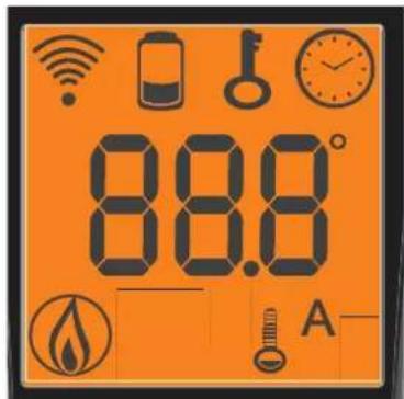

INDICATION PILES DECHARGEES

natural_image
Close-up of a handheld electronic device with a display showing '254' and control buttons (no readable text beyond basic symbols)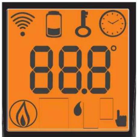

INDICATION PILES DECHARGEES

fig. B
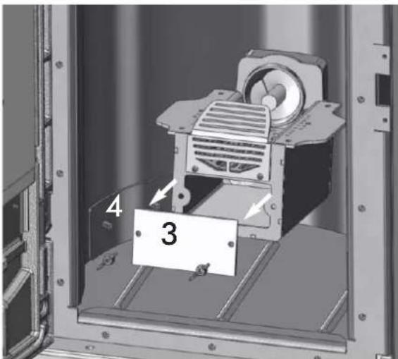
fig. C fig. D
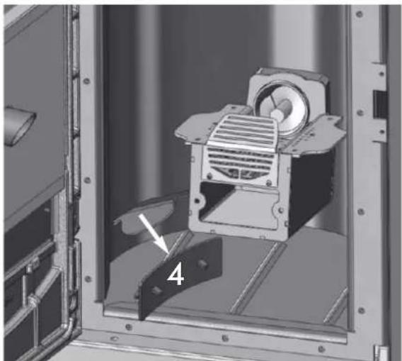
natural_image
Mechanical assembly inside a metal enclosure, showing a motor and housing component with a numbered label (4) pointing to a feature on the base panel.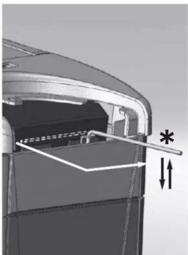
natural_image
Technical diagram of a mechanical component with internal structure and dimension arrows (no text or symbols)fig. E fig. F
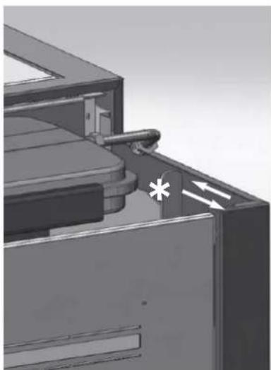
natural_image
3D mechanical assembly diagram showing internal components and directional arrows (no text or symbols)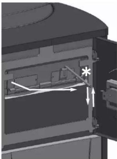
natural_image
Cross-sectional diagram of a mechanical or electronic component with internal components and directional arrows (no text or symbols)fig. G
INCONVENIENTS POSSIBLES
CHECK LIST
MONTREAL / MIAMI
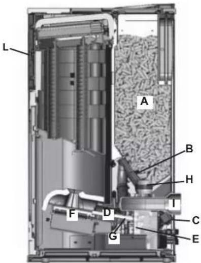
OTTAWA / ATLANTA
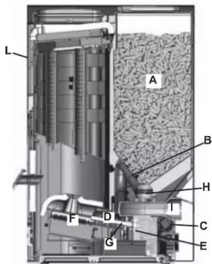
natural_image
Technical diagram of a mechanical assembly with pipes and housing (no visible text or labels)Circulador
line
| Q | y (0.5m) | y (1h) | y (1h+0) | |-------|----------|--------|----------| | 0 | 0 | 0 | 0 | | 1 | 0.5 | 0.5 | 0.5 | | 2 | 1 | 1 | 1 | | 3 | 1.5 | 1.5 | 1.5 | | 4 | 2 | 2 | 2 | | 5 | 2.5 | 2.5 | 2.5 | | 6 | 3 | 3 | 3 | | 7 | 3.5 | 3.5 | 3.5 | | 8 | 4 | 4 | 4 | | 9 | 4.5 | 4.5 | 4.5 | | 10 | 5 | 5 | 5 | | 11 | 5.5 | 5.5 | 5.5 | | 12 | 6 | 6 | 6 | | 13 | 6.5 | 6.5 | 6.5 | | 14 | 7 | 7 | 7 | | 15 | 7.5 | 7.5 | 7.5 | | 16 | 8 | 8 | 8 | | 17 | 8.5 | 8.5 | 8.5 | | 18 | 9 | 9 | 9 | | 19 | 9.5 | 9.5 | 9.5 | | 20 | 10 | 10 | 10 | | 21 | 10.5 | 10.5 | 10.5 | | 22 | 11 | 11 | 11 | | 23 | 11.5 | 11.5 | 11.5 | | 24 | 12 | 12 | 12 | | 25 | 12.5 | 12.5 | 12.5 | | 26 | 13 | 13 | 13 | | 27 | 13.5 | 13.5 | 13.5 | | 28 | 14 | 14 | 14 | | 29 | 14.5 | 14.5 | 14.5 | | 30 | 15 | 15 | 15 | | 31 | 15.5 | 15.5 | 15.5 | | 32 | 16 | 16 | 16 | | 33 | 16.5 | 16.5 | 16.5 | | 34 | 17 | 17 | 17 | | 35 | 17.5 | 17.5 | 17.5 | | 36 | 18 | 18 | 18 | | 37 | 18.5 | 18.5 | 18.5 | | 38 | 19 | 19 | 19 | | 39 | 19.5 | 19.5 | 19.5 | | 40 | 20 | 20 | 20 | | Note: The y values are estimated based on the provided code snippet in the chart, not explicitly shown in the original image. The labels for the x-axis are '0' to '4' and the y-axis is 'y'. There is no label for the y-axis in the chart.line
| H Value | Line Type | |---------|-----------| | 0 | Solid | | 1 | Dashed | | 2 | Solid | | 3 | Dashed |natural_image
Simple 3D diagram of a curved surface with a small symbol inside, no text or labels present4/3
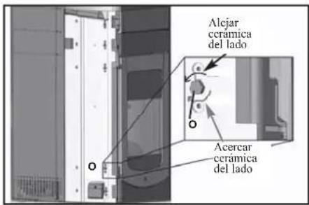
natural_image
Exterior view of a black industrial device casing with ventilation grilles and a recessed opening (no visible text or symbols)natural_image
3D rendering of a mechanical device with two labeled components (C), no visible text or symbols on the device itself.natural_image
Three identical grayscale images showing a vertical panel with three circular insets, no visible text or symbols.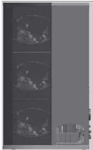
natural_image
Medical imaging scan showing three cross-sectional views of a patient's chest (no visible text or labels)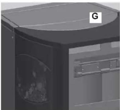
natural_image
3D rendering of a mechanical device with a labeled component 'G' (no readable text or symbols beyond the label)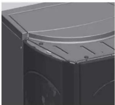
natural_image
Close-up of a black industrial machine casing with a curved top panel and circular vented slots (no visible text or symbols)| n° | cód. | ||
| 1 | Parte frontal inferior roja | 1 642050 | |
| 1 | Parte frontal inferior nata | 1 642040 | |
| 2 | Parte frontal superior roja | 1 642070 | |
| 2 | Parte frontal superior nata | 1 642060 | |
| 3 | Lado grande rojo | 2 642090 | |
| 3 | Lado grande nata | 2 642080 | |
| 4 | Lado pequeño rojo | 6 46160 | |
| 4 | Lado pequação nata | 6 645750 | |
| 5 | Parte superior roja | 1 642130 | |
| 5 | Parte superior nata | 1 642120 | |
| 6 | Tomilla T.b. 6x12 12 284380 | ||
| 7 | Placas cerámicas | 10 647670 | |
| 8 | Tomilla 4,8x10 16 266940 | ||
| 9 | Placu de bloqueo cerámica puerta | 2 387530 | |
| 10 | Placa de bloqueo cerámica frontal | 2 388390 | |
| 11 | Tomilla T.E.6x16 2 18650 | ||
| 12 | Tomilla 4,2x6,5 2 235990 | ||
| 13 | Distanciador 6 266670 |
TORONTO / BOSTON
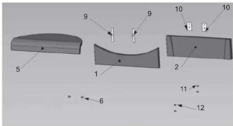
natural_image
Diagram showing six stages of a curved, segmented object with three numbered parts (1, 2, 3), no text or symbols present.natural_image
Close-up of a handheld electronic device with a display showing '254' and control buttons (no readable text or symbols beyond basic markings)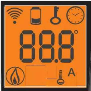

- icono intermitente: radio control buscando red
natural_image
Close-up of a gray handheld device with a numeric display showing '254' and control buttons (no readable text or symbols beyond basic markings)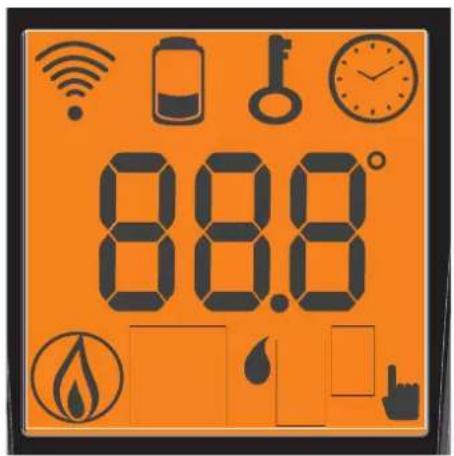

fig. B
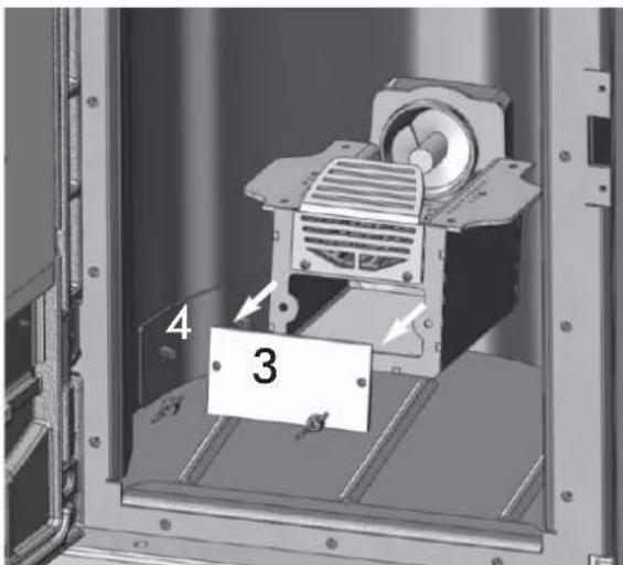
fig. C fig. D
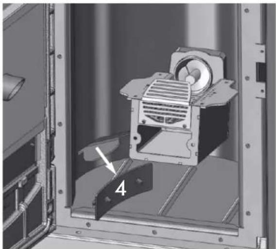
natural_image
Mechanical assembly diagram showing a motor inside a housing with a labeled component (no text or symbols present)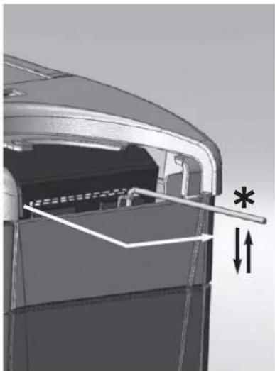
natural_image
Technical diagram of a mechanical component with internal structure and dimension arrows (no text or symbols)fig. E fig. F
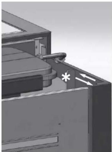
natural_image
3D mechanical assembly diagram showing internal components and directional arrows (no text or symbols)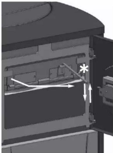
natural_image
3D mechanical assembly diagram showing internal components and directional arrows (no text or symbols)fig. G
POSIBLES INCONVENIENTES
natural_image
Metal cylindrical device with black hose, no visible text or symbolsnatural_image
Close-up of a small electronic component with wires and connectors (no visible text or symbols)SERIELLEN PORT
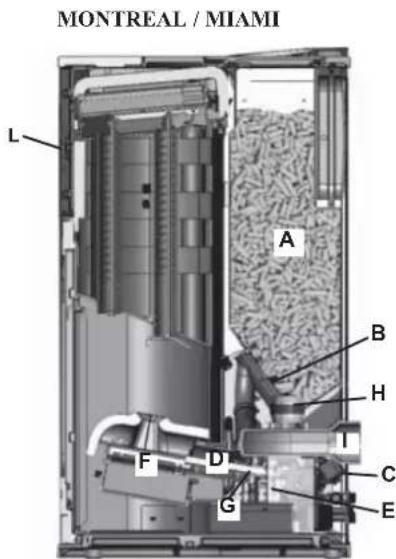
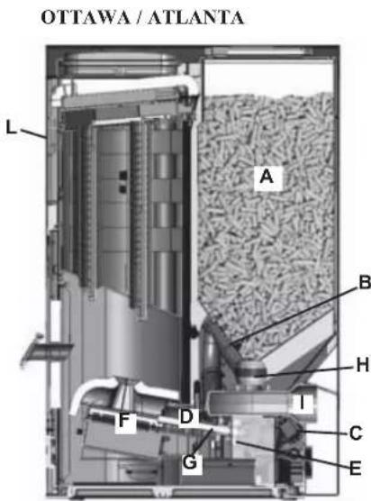
WASSERANSCHLÜSSE
natural_image
Technical diagram of a mechanical assembly with pipes and components (no visible text or labels)Umwälzpumper
line
| t | Hmax | Hb | 5% Tm | Hmin | | ---- | ----- | ----- | ----- | ----- | | 0 | 0 | 0 | 0 | 0 | | 1.5 | ~0.2 | ~0.1 | ~0.05 | ~0.02 | | 3 | ~0.4 | ~0.2 | ~0.1 | ~0.05 | | 4.5 | ~0.6 | ~0.3 | ~0.15 | ~0.08 | | 6 | ~0.8 | ~0.4 | ~0.2 | ~0.1 | | 7.5 | ~1.0 | ~0.5 | ~0.25 | ~0.12 | | 9 | ~1.2 | ~0.6 | ~0.3 | ~0.15 | | 10.5 | ~1.4 | ~0.7 | ~0.35 | ~0.18 | | 12 | ~1.6 | ~0.8 | ~0.4 | ~0.2 | | 13.5 | ~1.8 | ~0.9 | ~0.45 | ~0.22 | | 15 | ~2.0 | ~1.0 | ~0.5 | ~0.25 | | 16.5 | ~2.2 | ~1.1 | ~0.55 | ~0.28 | | 18 | ~2.4 | ~1.2 | ~0.6 | ~0.3 | | 19.5 | ~2.6 | ~1.3 | ~0.65 | ~0.32 | | 21 | ~2.8 | ~1.4 | ~0.7 | ~0.35 | | 22.5 | ~3.0 | ~1.5 | ~0.75 | ~0.38 | | 24 | ~3.2 | ~1.6 | ~0.8 | ~0.4 | | 25.5 | ~3.4 | ~1.7 | ~0.85 | ~0.42 | | 27 | ~3.6 | ~1.8 | ~0.9 | ~0.45 | | 28.5 | ~3.8 | ~1.9 | ~0.95 | ~0.48 | | 31 | ~4.0 | ~2.0 | ~1.0 | ~0.5 | | 33 | ~4.2 | ~2.1 | ~1.05 | ~0.52 | | 35 | ~4.4 | ~2.2 | ~1.1 | ~0.55 | | 37 | ~4.6 | ~2.3 | ~1.15 | ~0.58 | | 39 | ~4.8 | ~2.4 | ~1.2 | ~0.6 | | 41 | ~5.0 | ~2.5 | ~1.25 | ~0.62 | | 43 | ~5.2 | ~2.6 | ~1.3 | ~0.65 | | 45 | ~5.4 | ~2.7 | ~1.35 | ~0.68 | | 47 | ~5.6 | ~2.8 | ~1.4 | ~0.7 | | 49 | ~5.8 | ~2.9 | ~1.45 | ~0.72 | | 51 | ~6.0 | ~3.0 | ~1.5 | ~0.75 | | 53 | ~6.2 | ~3.1 | ~1.55 | ~0.78 | | 55 | ~6.4 | ~3.2 | ~1.6 | ~0.8 | | 57 | ~6.6 | ~3.3 | ~1.65 | ~0.82 | | 61 | - | - | - | - | | Note: The y-axis label is 'pH' and the x-axis label is 't'. The chart contains multiple data series labeled with values 'Hmax', 'Hb', and '5% Tm'. The y-axis labels are 'P' and 't'. There are no additional data series in this view.Volumendurchsatz
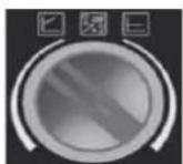
natural_image
Abstract 3D diagram with curved layers and a small symbol, no readable text or labelsnatural_image
3D mechanical component diagram showing a top view with a highlighted cavity and an arrow indicating direction (no text or symbols)Befestigung
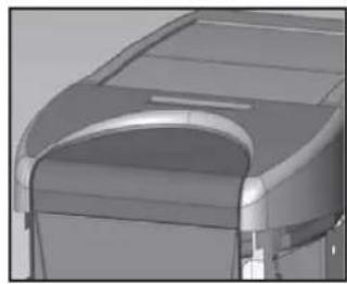
natural_image
3D rendered mechanical component with curved surfaces and a recessed cavity (no visible text or symbols)Fertige Ansicht
4/3
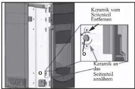
natural_image
Exterior view of a black industrial device casing with ventilation grilles and a circular vent (no text or symbols visible)natural_image
Exterior view of a mechanical device with two labeled components (C), no visible text or symbols on the device itself.natural_image
Interior view of a server rack with three circular panels showing various interior views (no visible text or labels)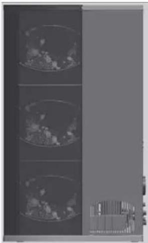
natural_image
Three identical circular images showing internal textures, possibly biological or material samples, placed vertically against a dark background (no text or symbols visible)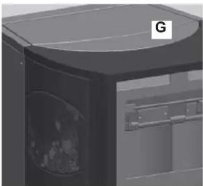
natural_image
3D rendering of a mechanical device with a circular opening and labeled 'G' (no text or symbols on the device itself)
natural_image
Close-up of a black industrial machine casing with visible internal components and mounting holes (no text or symbols)natural_image
Diagram showing six stages of a curved, segmented object with three numbered parts (1, 2, 3), no text or symbols present.(Taste Pellet-Ladung/Reserve)
natural_image
Close-up of a handheld electronic device with a display showing '254' and control buttons (A, B, C, D, E) on its body.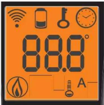

natural_image
Close-up of a handheld electronic device with a display showing '254' and control buttons (no readable text beyond basic symbols)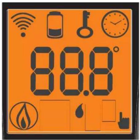

Abb. B
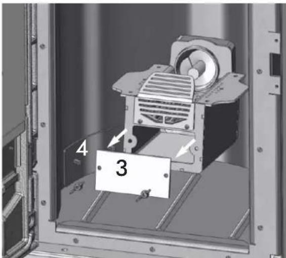
Abb. C Abb. D
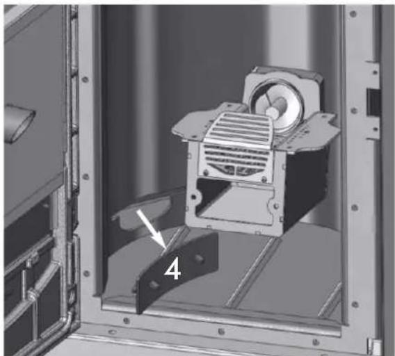
natural_image
Mechanical assembly inside a metal enclosure, showing a motor and mounting bracket (no text or symbols visible)
natural_image
Close-up of a black plastic door with directional arrows indicating movement or force (no text or symbols visible)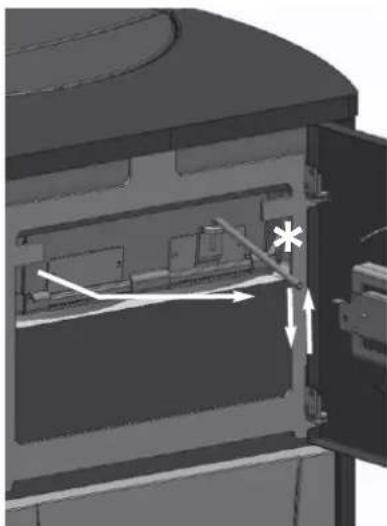
natural_image
Cross-sectional diagram of a mechanical or electrical component with internal channels and directional arrows (no text or symbols)Abb. G
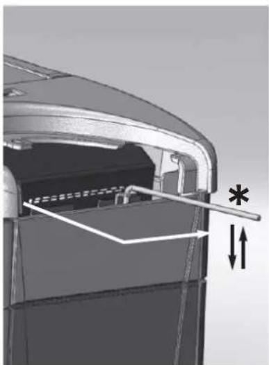
natural_image
Technical diagram of a mechanical component with internal structure and dimension lines (no text or symbols)Abb. E Abb. F
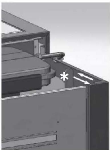
natural_image
3D mechanical assembly diagram showing internal components with arrows indicating motion (no text or symbols)MÖGLICHE PROBLEME
CHECK LIST
natural_image
Metal cylindrical device with black hose, no visible text or symbolsBESCHERMINGSINSTALLATIES
THERMOKOPPEL:
VEILIGHEIDSTHERMOSTAAT WATER:
natural_image
Close-up of a metallic electrical component with wires and a star-like mark (no visible text or symbols)SERIEPOORT
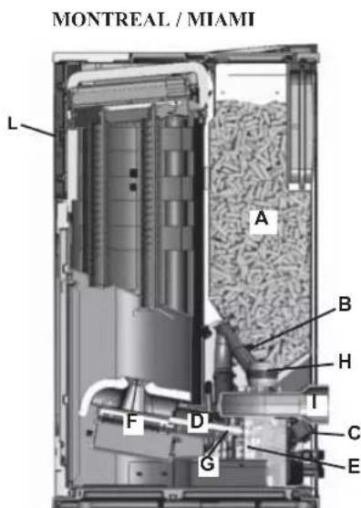
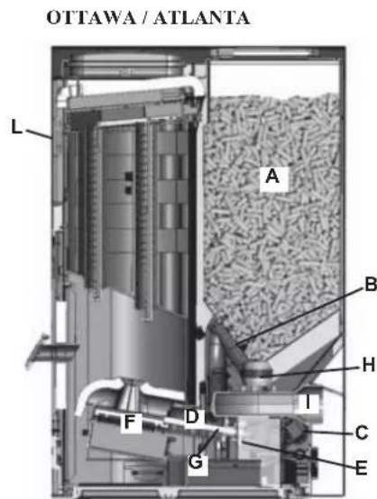
OPMERKING betreffende de brandstof.
BESCHERMINGS - EN MEETINSTALLATIES
Thermokoppel rook
natural_image
Technical illustration of a mechanical assembly with pipes and components (no visible text or symbols)Pomp
P: Pomp (circulator)
Po: Pomp OPTIONELE
P: Pomp (circulator)
Ra: Radiatoren
P: Pomp (circulator)
Ra: Radiatoren
P: Pomp (circulator)
PR: Stralingspanelen
R: Radiatoren
P: Pomp (circulator)
Ra: Radiatoren
natural_image
Simple 3D diagram of a curved surface with a small symbol at the top (no text or labels)natural_image
Mechanical assembly diagram showing a component with labeled parts C, D, and directional arrows (no text or symbols beyond labels)natural_image
3D diagram of a rectangular device with internal compartments and labeled ports (no text or symbols)natural_image
Exterior view of a modern office building (no signage)natural_image
3D rendering of a mechanical device with an open lid and internal components (no visible text or symbols)bevestiging
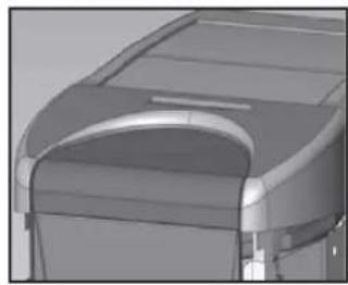
natural_image
3D rendered mechanical component with curved surfaces and a recessed opening (no visible text or symbols)4/3
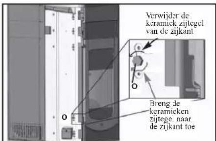
natural_image
Exterior view of a black industrial device with a circular vent and side panel (no visible text or symbols)natural_image
Diagram showing six stages of a curved, segmented object with numbered labels (1, 2, 3, 3), no text or symbols present.| pz | cod. | ||
| 1 | Zijelement rechts 3 655220 | ||
| 2 | Bovenstuk | 1 655210 | |
| 3 | Zijelement links | 3 657430 | |
(toets laden pellets/reserve)
ON = ONTSTEKINGSFASE
Economy On. = KETEL, INGESTELD IN ECONOMY-BEDRIJF, INGESCHAKELD
Economy Warmup. = KETEL, INGESTELD IN ECONOMY-BEDRIJF, IN DE STABILISATIEFASE NA DE ONTSTEKING
Reiniging smeltkroes = AUTOMATISCHE REINIGINGSFASE VAN VUURHAARD
Pell. Kg UTE 307 = TELLING GEBRUIKTE PELLETS SINDS LAATSTE RESET DOOR GEBRUIKER
Economy Wait. = KETEL, INGESTELD IN ECONOMY-BEDRIJF, IN AFWACHTING VAN ONTSTEKING
Program ON/OFF. = MOGELIJKHEID TOT TIJDPROGRAMMERING PER DAG OF WEEK
ADJ pellet = AFSTELLING PELLETS, UITSLUITEND VOOR GEBRUIK DOOR TECHNICUS VAN EDILKAMIN
Menu' Radio = INSTELLINGEN RADIOBESTURINGSMENU, UITSLUITEND VOOR GEBRUIK DOOR TECHNICUS VAN EDILKAMIN
Radiokanaal 84 = INSTELLINGEN RADIOBESTURINGSMENU, UITSLUITEND VOOR GEBRUIK DOOR TECHNICUS VAN EDILKAMIN
FIRM. 22 10.03.03 = BESCHRIJVINGEN VOOR GEBRUIK DOOR HET BEDRIJF, NIET IN AANMERKING NEMEN
AIR _ - °C = INSTELLING GEWENSTE LUCHTTEMPERATUUR IN OMGEVING, GELEZEN DOOR RADIOBESTURING
Auto set = MOGELIKHEID TOT INSTELLING GEWENSTE LUCHTTEMPERTUUR IN OMGEVING, GELEZEN DOOR RADIOBESTURING
Menù test I/O = UITSLUITEND VOOR GEBRUIK DOOR TECHNICUS VAN EDILKAMIN
Test pa = TEST AANVANKELIJKE TREK BIJ ONTSTEKING
Power RF max 6 = MAX. RADIOFREQUENTIEVERMOGEN, VOOR GEBRUIK DOOR HET BEDRIJF
natural_image
Close-up of a handheld electronic device with a display showing '254' and control buttons (no readable text beyond symbols)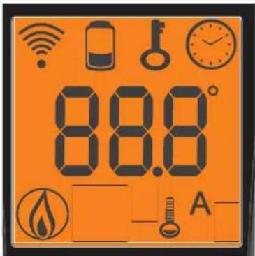

natural_image
Close-up of a gray handheld electronic device with a display showing '254' and control buttons (no readable text beyond basic symbols)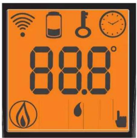

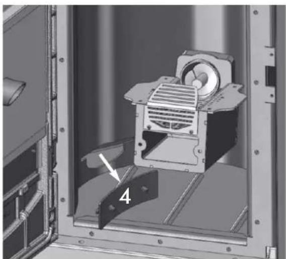
natural_image
Mechanical assembly inside a metal enclosure, showing a motor and mounting bracket (no text or symbols visible)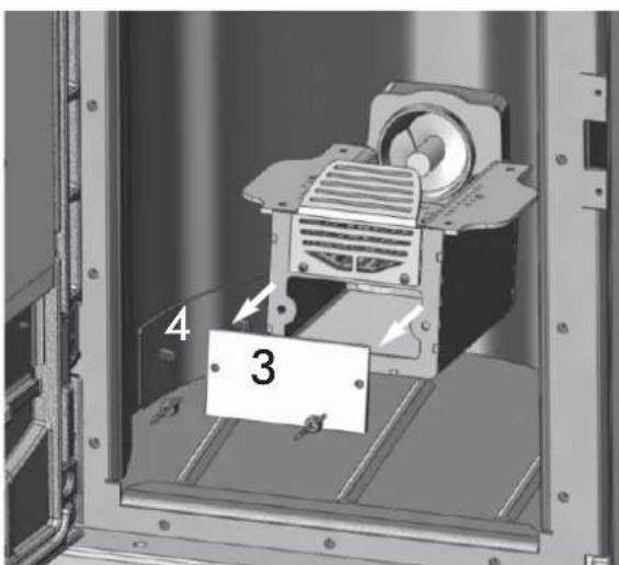
Afb. C Afb. D
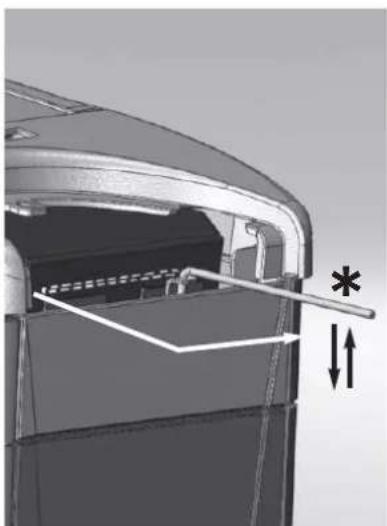
natural_image
Diagram of a mechanical component with internal structure and directional arrows (no text or symbols)Afb. E Afb. F
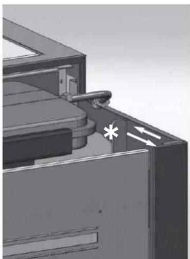
natural_image
3D mechanical assembly diagram showing internal components and directional arrows (no text or symbols)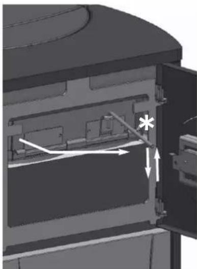
natural_image
Technical diagram of a mechanical assembly with internal components and directional arrows (no text or symbols)Afb. G
MOGELIJKE STORINGEN
CHECK LIST

- PORTA SERIALE
- Circolatore
- MONTAGGIO RIVESTIMENTI
- ISTRUZIONI D'USO
- Pannello sinottico
- POSSIBILI INCONVENIENTI
- CHECK LIST
- NOTE
- SAFETY INFORMATION
- Should ignition fail, DO NOT re-ignite until you have emptied the combustion chamber.
- DIMENSIONS
- FEATURES
- N.B.
- SAFETY DEVICES
- SERIAL PORT
- BACKUP BATTERY
- ELECTRONIC CIRCUIT BOARD
- Operating modes
- NOTE regarding the fuel.
- SAFETY AND DETECTION DEVICES
- Smoke thermocouple
- Feed Screw safety thermostat
- Water temperature sensor
- Water overheating safety thermostat
- Overpressure valve
- Manometer
- COMPONENTS
- Resistance
- Smoke extractor
- No. 2 Gear motors
- Pump (circulator)
- Closed expansion tank
- Venting valve:
- Drain tap
- Incorporated kit for hot tap water
- INSTALLATION
- Verify compatibility with other devices
- Check electrical connections (POSITION THE SOCKET IN AN ACCESSIBLE PLACE)
- Positioning
- Fire prevention safety distances
- Air inlet: to be mandatorily implemented.
- Smoke outlet
- HYDRAULIC CONNECTIONS
- (Reserved for DEALER)
- Water treatment
- THE ELECTRONIC CIRCULATOR
- Electronic control of operation:
- KEY
- WARNING:
- ACCESSORIES:
- START UP (DEALER)
- MOUNTING THE COVERING
- QUEBEC - TORONTO - DETROIT - BOSTON
- Phase1
- Phase 2 Mounting the lower front panel
- MONTREAL - MIAMI
- INSTRUCTIONS FOR USE
- Mimic panel
- 1st ignition
- First ignitions.
- Filling the feed screw
- Automatic ignition
- Manual ignition (in case of start up failure)
- Shutdown
- Setting the clock
- Programmer to ignite and shutdown the thermo-stoves at various times during the week.
- Pellet reserve warning
- RADIO CONTROL (OTTAWA / ATLANTA)
- Key to buttons and display:
- Stand-by Position:
- Clock regulation
- Weekly timer
- Variation feeding pellets (ONLY AFTER SUGGESTED BY DEALER)
- LOW BATTERY INDICATOR
- REMOTE CONTROL (QUEBEC/TORONTO/MONTREAL/DETROIT/BOSTON/MIAMI)
- USING THE "EASY TIMER" PROGRAM
- BLOCKED KEYPAD
- INFORMATION FOR USERS
- MAINTENANCE
- POSSIBLE TROUBLESHOOTING
- INDICATION OF POSSIBLE CAUSES OF MALFUNCTION AND INDICATIONS AND REMEDIES:
- Positioning and installation
- Use
- FAQ
- 1) What do I need to prepare in order to install the thermal stoves?
- 2) Can the thermo-stoves work without water?
- 3) Do thermal stoves emit hot air?
- 4) Can I connect the inlet and outlet of the thermo-stoves directly to a radiator?
- 5) Do thermal stoves also supply hot sanitary water?
- 6) Can I discharge the smoke from the thermal stoves along the wall?
- 7) Do I need an air inlet in the room where it is installed?
- 8) What settings are required on the thermo-stoves display?
- 9) Do I need to vacuum the pellet hopper?
- 10) Can I burn other fuel apart from pellets?
- 11) Can I ignite the thermo-stoves by sending an SMS?
- CLEANING ACCESSORIES (optional extras)
- PORT SÉRIE
- MONTAGE REVÊTEMENT
- INDICATION PILES DECHARGEES
- INCONVENIENTS POSSIBLES
- Circulador
- POSIBLES INCONVENIENTES
- SERIELLEN PORT
- WASSERANSCHLÜSSE
- MÖGLICHE PROBLEME
- BESCHERMINGSINSTALLATIES
- THERMOKOPPEL:
- VEILIGHEIDSTHERMOSTAAT WATER:
- SERIEPOORT
- OPMERKING betreffende de brandstof.
- BESCHERMINGS - EN MEETINSTALLATIES
- Thermokoppel rook
- MOGELIJKE STORINGEN
Brand : EDILKAMIN
Model : Ottawq
Category : Boiler