TV 230 - Measuring equipment Testboy - Free user manual and instructions
Find the device manual for free TV 230 Testboy in PDF.
| Product type | Bipolar voltage tester with clamp ammeter |
| Brand | Testboy |
| Model | TV 230 |
| Category | Measuring equipment |
| Power supply | 2 AAA 1.5 V batteries |
| AC voltage range | 1 ... 1000 V (TRMS) |
| DC voltage range | 1 ... 1500 V |
| AC/DC current measurement | 0.1 ... 200 A, 45 ... 65 Hz |
| Continuity test | 0.1 ... 500 kΩ |
| Frequency measurement | 1 ... 800 Hz |
| Protection rating | IP64 |
| Overvoltage category | CAT IV 600 V, CAT III 1000 V |
| Operating temperature | -15 °C to +55 °C |
| Display | Backlit LCD, LEDs |
| Main functions | AC/DC voltage test, current test, continuity test, diode test, resistance test, phase detection, rotating field test, NCV, Data Hold, work area lighting |
| Compliance | EN 61243-3:2014, IEC 61010-1:2010 |
| Maintenance | Cleaning with a damp cloth and mild detergent |
| Safety | Use only by qualified electricians; observe the five safety rules; do not use in humid environment; replace batteries immediately if discharged |
Frequently Asked Questions - TV 230 Testboy
User questions about TV 230 Testboy
0 question about this device. Answer the ones you know or ask your own.
Ask a new question about this device
Download the instructions for your Measuring equipment in PDF format for free! Find your manual TV 230 - Testboy and take your electronic device back in hand. On this page are published all the documents necessary for the use of your device. TV 230 by Testboy.
USER MANUAL TV 230 Testboy
text_image
BAT M BODY CAT Ⅲ 1000VTestboy® TV 230
Version 1.3

Testboy® TV 230 3
Bedienungsanleitung

Testboy® TV 230 11
Operating instructions

Testboy® TV 230 19
Cd = Cadmium, Hg = Quecksilber, Pb = Blei, Mn = Mangan, Li = Lithium.
Safety instructions 14
General 15
Function 15
Self test / Auto Power-Off 15
Check voltage 15
Low voltage display 16
Current test 16
Zero 16
Continuity check 16
Diode test 16
Resistance test 16
NCV function 16
DATA HOLD function 16
Phase check 16
Rotary field test (> 170 V AC) 17
One-hand test (e.g. earthed socket) 17
Test location lighting 17
Backlight 17
Frequency display 17
Cleaning 17
Maintenance 17
Battery change 18
Technical data 18
Safety information

WARNING

Before using, carefully read these instructions. If the instrument is not used as intended by the manufacturer, the protection already provided can be influenced.
WARNING
Sources of danger are, for example, mechanical parts, which may cause serious personal injury. Objects are also at risk (e.g. damage to the instrument).
WARNING
An electric shock can result in death or serious personal injury and endanger the function of objects (e.g. damage to the instrument).

WARNING
Unauthorised modification and / or changes to the instrument are not permitted, for reasons of safety and approval (CE). In order to ensure safe and reliable operation using the instrument, you must always comply with the safety instructions, warnings and the information contained in the section "Intended use".
WARNING
Comply with the following specifications before using the instrument:
Do not operate the instrument anywhere near electric welding equipment, induction heaters or other electromagnetic fields.
After abrupt changes in temperature, in order to stabilise the IR sensor, the instrument must be allowed to adjust to the new ambient temperature for approx. 30 minutes before using it.
At lower temperatures of less than 5 °C, the readiness of the voltage tester can be impaired. Please provide sufficient power supply by using suitable batteries which are also specified for the appointed temperature range!
Do not expose the instrument to high temperatures for a long period of time.
Avoid dusty and humid environments.
The voltage tester and accessories are not toys, and must be kept out of the reach of children!
When working in industrial facilities, comply at all times with the specifications of the accident prevention regulations for electrical systems and equipment as established by the employer's liability insurance association.

Comply with the five safety rules:
1 Disconnect
2 Ensure that the instrument cannot be switched back on again
3 Ensure isolation from the power supply (check that there is no voltage on both poles)
4 Earth and short-circuit
5 Cover adjacent live parts

WARNING
In comparison to the reference value of 100 kΩ, a voltage tester with relatively low impedance does not indicate all interference voltages with an original value above the ELV. On contact with the parts of the system to be tested, due to discharge, the voltage tester can temporarily diminish the interference voltages up to a level less than the ELV; however, after removing the voltage tester, the interference voltage returns to its original value.
In comparison to the reference value of 100 kΩ, a voltage tester with relatively high internal impedance at the existing interference voltage cannot clearly indicate "operating voltage not present".
If the indication "Voltage present" does not appear, before starting work, it is strongly recommended to insert the earthing device.
If the indication "Voltage present" appears for a part that is considered to be separate from the system, it is strongly recommended to take additional action (e.g.: Use a suitable voltage tester, visual check of the separating point in the electrical circuit etc.) to verify and determine the condition of the "Operating voltage not present" of the part of the system to be tested and that the voltage indicated by the voltage tester is an interference voltage.
It is not allowed to use the delivered exchangeable test lead in combination with other devices which are not explained in this manual.
Intended use
Only intended for use by qualified electricians and specialized personnel.
The instrument is only intended for the applications described in the operating instructions, such as AC, DC and continuity checks, phase and rotating field tests. Any other usage is forbidden, and may result in accidents or destruction of the instrument. Any such misapplication will result in the immediate expiry of all guarantee and warranty claims on the part of the operator against the manufacturer.
Everybody who uses this test instrument should be appropriately trained and be familiar with the required safety precautions and the procedure for checking the correct function of the instrument, before and after using each time, particularly for hazards occurring during voltage testing.

In order to protect the instrument from damage, remove the batteries if the instrument is not in use for a long period of time.

We assume no liability for damage to property or personal injury resulting from improper handling or non-compliance with the safety instructions. In such cases, any warranty claim becomes invalid. An exclamation mark in a triangle indicates safety instructions in the operating instructions. Read the instructions through before beginning initial commissioning. This instrument is CE-approved and thus fulfils the required guidelines.
We reserve the right to change specifications without prior notice © 2023 Testboy GmbH, Germany.
Disclaimer

The warranty claim expires in cases of damage caused by failure to comply with the instructions! We assume no liability for any resulting damage!
Testboy is not responsible for damage resulting from
failure to observe the instructions
changes to the product that have not been approved by Testboy or
the use of spare parts that have not been manufactured or approved by Testboy
The use of alcohol, drugs or medication.
Accuracy of the operating instructions
These operating instructions have been compiled with due care and attention. No guarantee is given that the data, illustrations and drawings are complete or correct. All rights reserved with regard to changes, printing mistakes and errors.
Disposal
Dear Testboy customer: purchasing our product gives you the option of returning the instrument to suitable collection points for waste electrical equipment at the end of its lifespan.

The WEEE directive regulates the return and recycling of electrical appliances. Manufacturers of electrical appliances are obliged to take back and recycle all electrical appliances free of charge. Electrical devices may then no longer be disposed of through conventional waste disposal channels. Electrical appliances must be recycled and disposed of separately. All equipment subject to this directive is marked with this logo.
Disposal of used batteries
As end user, you are legally obliged (battery law) to return all used batteries; disposal by the household waste is forbidden!
Batteries containing contaminant material are labelled with this symbol indicating that they may not be disposed of in normal domestic waste.
The designations for the essential heavy metals are, amongst others:
Cd = Cadmium, Hg = Mercury, Pb = Lead, Mn = Manganese, Li = Lithium.
You can return your used batteries to collection points in your community or anywhere where batteries are sold free-of-charge.
Certificate of quality
All activities and processes carried out within Testboy GmbH relating to quality are subject to ongoing monitoring within the framework of a Quality Management System. Furthermore, Testboy GmbH confirms that the testing equipment and instruments used during the calibration process are subject to an ongoing inspection process.
Declaration of conformity
The product conforms to the most recent directives. For more information, go to www.testboy.de
Operation
Thank you for choosing the Testboy ^® TV 230, a forked current clamp including a two-pole voltage tester with LCD display. DC voltages (1 V to 1500 V) and AC voltages (1 V to 1000 V) against earth, polarity, rotating field direction and continuity tests up to 500 kΩ can be performed.
The Testboy ^® TV 230 can also be used in harsh environments due to its high degree of protection (IP64).
The display of the Testboy TV 230 is intended as a guide value for two-pole voltage testing, not as a measured value.
Please use suitable measuring equipment for this purpose!
Safety instructions
You have chosen a device that offers you a high level of safety. To ensure safe and correct use, it is essential that you read these operating instructions completely before using the device for the first time.
The following safety precautions apply:
The device must be checked for function shortly before use (VDE regulation 0105, part 1). Make sure that the test line and the device are in perfect condition. Check the device at a known voltage source, e.g. 230 V socket.
If the display of one or more functions fails, the device must no longer be used and must be checked by qualified personnel.
Only touch the device by the handles below the mechanical marking, avoid touching the test prods!
Only perform tests for freedom from voltage on two poles!
The device must not be operated in a damp environment!
Do not use with the battery compartment open! The test probes must be removed from the test circuit during a battery change.
A perfect display is ensured in the temperature range from -15 °C to +55 °C.
Always keep the device dry and clean. The housing may only be cleaned with a damp cloth.
The additionally indicating sound signal and vibration at voltages > 50 V AC / 120 V DC are only for warning of life-threatening voltages, not for testing purposes!
Replace the batteries immediately if the device switches off again shortly after or as soon as it is switched on.
The various indicating signals of the voltage tester (including the ELV limit value) must not be used for measuring purposes.
Do not use any test leads on this unit other than the test leads supplied with the unit.
It is not allowed to use the delivered exchangeable test lead in combination with other devices which are not explained in this manual.
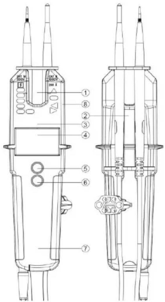
- Opening for current measurement
- Test leads
- LED display
- LCD display
- On/Off and function key
- Flashlight and function key
- Battery compartment
- Cable break sensor area
text_image
DCT N 500V CAT B 800 V 200 A ① ⑧ ② ③ ④ ⑤ ⑥ ⑦General
Voltages have priority. If no voltage is applied to the test probes ( ≥ 1 V), the device is in continuity test mode.
Function
To switch on the device, press the On/Off key.
The device switches off automatically after about 10 seconds if no signal is detected at the test probes. The measuring point illumination switches off after about 30 seconds.
Screwing or unscrewing the test probe adapters makes testing at sockets more convenient.
The nominal current In is a maximum of 3.5 mA.
Self test / Auto Power-Off
When the instrument is switched on for the first time, either when new batteries are inserted, when the test probes are held together or by pressing the power button when the instrument is off, all the indicators in the LCD display light up briefly. Shortly thereafter, the instrument switches to voltage mode. If the display of one or more functions fails, the device may no longer be used and must be checked by qualified personnel. Hold the test probes together for testing; this should be done shortly before and after use to ensure that the device is ready for operation. If the LCD does not light up or only lights up weakly, the batteries must be replaced. If the instrument does not work even with new batteries, it must be protected from misuse. After some time without use, the device will automatically switch off by the "Auto Power Off" function.
Check voltage
Contact the object to be measured with the test probes. The test probes can be held in the hand or plugged in at the top of the housing. When the test probes are plugged in, they have a distance of 19 mm to be plugged into sockets with one hand. The applied voltage is indicated with the LEDs and on the LCD. The sound generator and vibration function turn on above a voltage of 50V AC or 120V DC.
The polarity is shown on the LCD display as follows:
AC: AC symbol lights up
+DC: DC symbol lights up
-DC: - and DC symbol light up
The polarity is indicated with the LEDs as follows (above 120V).
AC: + and - 120V LED are on
+DC: +120V LED is on
-DC: -120V LED is on
If the test probe L2 is applied to a positive potential (negative potential), +DC (-DC) is displayed. The L or R LED may light up during the voltage test.
When the batteries are empty, only the "dangerous voltage" LED lights up at > 50V AC/DC.
Low voltage display
To enter the low-voltage mode, the on/off function key must be pressed several times until "<10V" appears on the display. In this mode, voltages from 1 V AC or DC can be measured. The continuity test is not available in this operating mode.
Current test
The On/Off function key is used to enter the current test mode. The A symbol appears in the display. In this mode, alternating currents between 0.1 A and 200 A can be tested. The current-carrying cable must be placed in the middle of the current clamp opening at the level of the left and right markings. Only double-insulated cables may be tested. The test probes must be stowed safely. If a voltage of 6 V is detected between the measuring tips, the unit switches to voltage change mode.
Zero
In current measurement mode, move the tester out of reach of live conductors, press both buttons until the LCD displays "Zero" and hold until the beeper beeps 3 times.
Continuity check
(Hold test probes together to switch on)
Select the "L Rx" mode with the on/off function key. Place the test probes on the line, fuse or similar to be tested. An acoustic signal sounds if the resistance is below 20 Ω. The continuity test is carried out in all operating modes except the mode for measuring small voltages. For resistances up to <500 kΩ, switch to the diode test. An acoustic signal sounds for continuity up to <500 kΩ. When a voltage of 6 V is detected, the unit automatically switches to voltage mode.
Diode test
If the diode test is selected with the On/Off function key, the "▶" symbol appears on the display. You can test the diode to be tested with the two test probes. The continuity indicator lights up and the beeper sounds when L1 is connected to the anode and L2 to the cathode. If the cathode and anode are connected in reverse, no continuity is indicated. If a voltage of about 6V is detected, the unit switches to voltage mode.
Resistance test
To enter the resistance test mode, press the on/off function key several times until the " " symbol is displayed. Connect the test probes to the test object. Resistance readings up to 100 k are shown on the display. For resistances below 20 , continuity is indicated by means of an acoustic signal. If a voltage of around 15 V is detected, the unit switches to voltage mode.
NCV function
If the On/Off function key is pressed several times, the NCV mode is entered. In this mode, the detection of the E-field can be used to search for a cable break, for example. The device is held with the sensor against the cable or line. The signal strength is displayed on the LCD. The test probes are to be stowed away.
DATA HOLD function
A long press (2 seconds) on the illumination/HOLD key activates the HOLD function and freezes the value. A short beep of the bee-per indicates the activation of this function. A short press on the "Flashlight/Function" key releases the frozen display. When the HOLD function is activated, the symbol is displayed on the LCD.
Phase check
Protective clothing and insulating locations can influence the function!
Touch a conductor with the test probe "L2" of the large handle. When a phase (pole >100 V AC), min. 100 V\~, is applied, the display "<L" shows the warning triangle and the red flashing LED as well as a vibration.

For the determination of the phase conductors, the perceptibility of the indication can be impaired, e.g. by insulating devices to protect against direct contact, in unfavorable positions, for example on wooden ladders or insulating floor coverings, a non-grounded voltage or also in unfavorable lighting conditions. For safety, perform a two-pole check to ensure that no voltage is present.
You can also determine the phase by checking the phase conductor against the protective earth conductor. For the phase conductor, the applied voltage should be displayed.

Make sure that an additional current flows via the protective conductor during this test. This adds to the current already present and could trigger the circuit breaker (F1)!
Rotary field test (> 170 V AC)
Protective clothing and insulating locations can affect the function.
Fully enclose handles L1 and L2 (see picture on page 7) below the mechanical mark.
Place the test probes L1 and L2 on two outer conductors (phases) and check whether the outer conductor voltage of e.g. 400 V is present.
A clockwise rotation sequence (phase L1 before phase L2) is given when the letter "R" appears in the display
A counterclockwise rotation sequence (phase L2 before phase L1) is given when the letter "L" appears in the display.
The rotating field determination must always be performed with the test probes reversed. The direction of rotation must change.
Notice:
The rotating field test is possible from 170 V, 50/60 Hz (phase against phase) in the grounded three-phase network.
The "third" phase (L3) is simulated by grasping the hand parts with the aid of a sensor in the device.
One-hand test (e.g. earthed socket)
The test leads can be plugged into the top of the TV 230 by means of the hook located on the collar of the test lead. The distance between the test probes is 19 mm, which is ideal for testing conventional sockets with one hand.
Test location lighting
The test location illumination is switched on or off again by pressing the light key for a longer time. Use them carefully, as the additional load will drain the batteries prematurely.
Backlight
The display backlight turns off automatically after a few seconds to save battery power and turns on again when the key is pressed.
Frequency display
The On/Off function key can be used to switch through to the frequency display. In the frequency display, the unit of measurement Hz is displayed on the LCD. If both test probes are connected to the test object, the device displays frequencies between 1 and 800 Hz. A frequency is only displayed if a voltage of at least 10 V is applied. The voltage is additionally displayed via the LEDs from a value of 120 V and the ELV LED indicates voltages >50VAC or >120VDC.
Cleaning
If the device has become dirty through daily use, the device can be cleaned with a damp cloth and some mild household cleaner. Never use harsh cleaners or solvents for cleaning.

To avoid electrical shock, do not allow moisture to enter the housing.
Maintenance
The device does not require any special maintenance except for the batteries when operated according to the operating instructions.
Battery change
If the batteries have run down, the battery symbol appears in the display and the device switches off if necessary. Please change the batteries immediately to ensure the accuracy of the test values.
Disconnect the test probes from the test circuit before opening the battery compartment!
To change the batteries, open the battery compartment on the main housing. To do this, loosen the screws alternately using a suitable screwdriver. Make sure that the polarity is correct when using the new batteries. Carefully close and screw the battery compartment back shut.
Without batteries, the device indicates an applied voltage above the ELV value by means of an LED.
At lower temperatures below 5^ C, the readiness of the voltage tester may be impaired. Please ensure sufficient power supply by using suitable batteries which are also specified for the temperature range used!

Batteries do not belong in the household waste. There is also a collection point near you!
Technical data
| Display | Backlit LC display / LEDs |
| Nominal voltage range | 1...1000 V AC (TRMS)1...1500 V DC |
| Current measurement | 0.1...200 A AC/DC, 45...65 Hz |
| Rotary field display | Yes |
| Frequency display | 1...800 Hz ±5% +5 digits |
| Nominal current In | < 3.5 mA |
| Phase testing pole | >100 V AC |
| Continuity check | 0,1...500 kΩ |
| Operating temperature | -15 to +55 °C, at >85% RH |
| Protection class | IP 64 |
| Overvoltage category | CAT IV 600 V, CAT III 1000 V |
| Test standard | EN 61243-3:2014, IEC 61010-1:2010 |
| Power supply | 2x 1.5 V type AAA Micro |
Table des matières
Cd = cadmium, Hg = kwikzilver, Pb = lood, Mn = mangaan, Li = lithium.
Germany info@testboy.de