SWK-100 - Boiler KOSPEL - Free user manual and instructions
Find the device manual for free SWK-100 KOSPEL in PDF.

| Product type | DHW storage tank (boiler) |
| Brand | Kospel |
| Model | SWK-100 |
| Capacity | 100 L |
| Nominal tank pressure | 0.6 MPa |
| Nominal temperature | 95 °C |
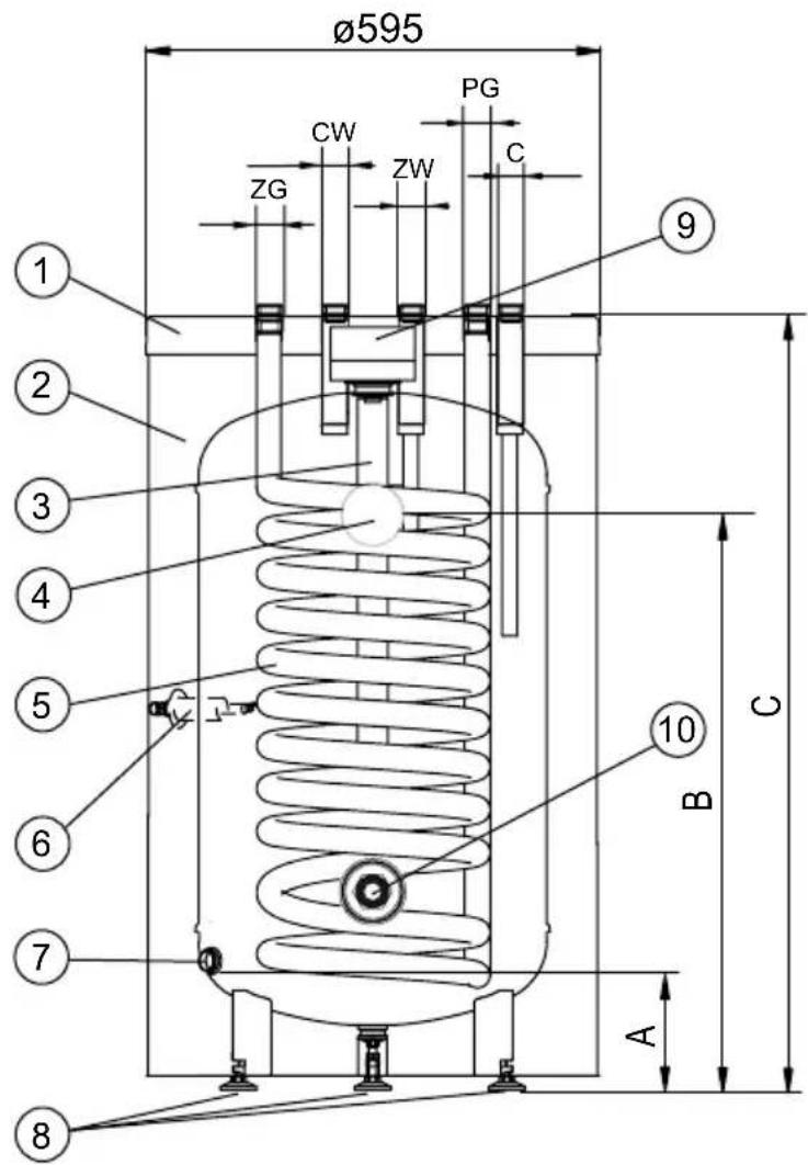
| Diameter | 595 mm |
| Height (C) | 906 mm |
| Empty weight | 58 kg |
| Corrosion protection | Magnesium anode |
| Magnesium anode (service code) | 01448 |
| Coil surface area | 0.82 m² |
| Coil volume | 5.3 dm³ |
| Coil power (80/10/45°C) | 25 kW |
| Coil power (55/10/45°C) | 7.5 kW |
| Safety valve | 6 bar (0.6 MPa) |
| Optional electrical supply | Electric heating element with thermostat (GRW-1.4/230; GRW-2.0/230; GRW-3.0/230; GRW-4.5/400) |
| Installation | By a certified professional, in vertical position, in a frost-free room |
| Maintenance | Annual anode inspection, replacement every 18 months; periodic cleaning by a professional; heat to 70°C periodically for hygiene |
| Warranty | Void if installation or use is not compliant |
Frequently Asked Questions - SWK-100 KOSPEL
User questions about SWK-100 KOSPEL
0 question about this device. Answer the ones you know or ask your own.
Ask a new question about this device
Download the instructions for your Boiler in PDF format for free! Find your manual SWK-100 - KOSPEL and take your electronic device back in hand. On this page are published all the documents necessary for the use of your device. SWK-100 by KOSPEL.
USER MANUAL SWK-100 KOSPEL
natural_image
Line drawing of a cylindrical container with circular and rectangular features, no text or symbols presenttext_image
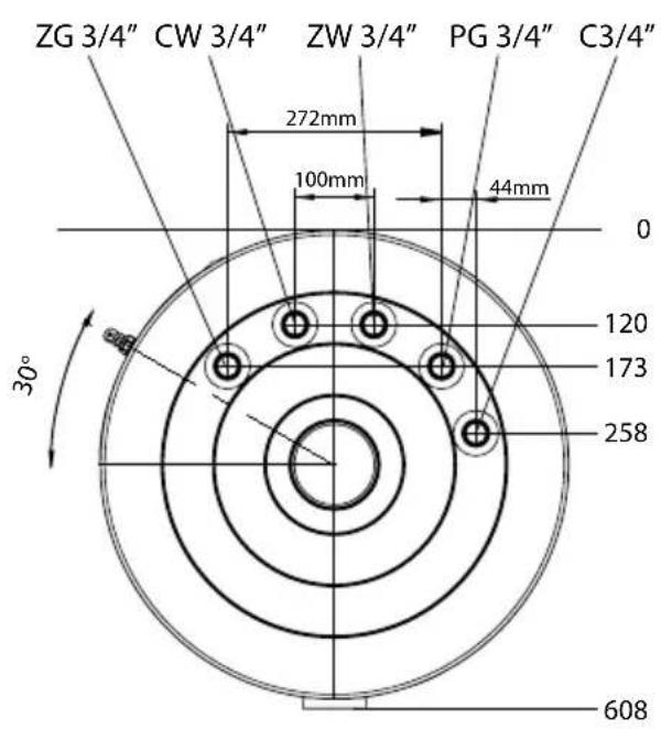
ZG 3/4" CW 3/4" ZW 3/4" PG 3/4" C3/4" 272mm 100mm 44mm 0 120 173 258 30° 608[1] - pokrywa górna
text_image
ZG 3/4" CW 3/4" ZW 3/4" PG 3/4" C3/4" 272mm 100mm 44mm 0 120 173 258 30° 608[1] - Deckel
- Read and strictly follow this assembly and operating instructions to ensure a long life and reliable cylinder operation.
- The manufacturer of this cylinder will not be liable for any damages due to the failure to follow the assembly and operating instructions.
- The cylinder must not be installed in rooms where the temperature may drop below 0^ C.
- The cylinder installation and the initial start-up, as well as all electrical and hydraulic work must be performed by a qualified professional installer-in strict accordance with assembly and operating instructions.
- The cylinder is designed for standing vertical installation- screw on three feet.
- The device must be installed in such a place and in such a way in order not to flood the room in case of the emergency water leak.
- Connections with water installation, central heating system, and solar collectors must be made in accordance with the diagram in this installation instruction. Failure to follow the installation instruction invalidate the warranty and may cause cylinder's damage.
- Connections with water installation must be made in accordance with the legally binding standards.
- The cylinder is a pressure appliance designed for connection with water installation the water pressure doesn't exceed 0,6 MPa. If the water pressure exceeds 0,6 MPa, the pressure reducing valve before cylinder must be fitted.
- A small leak from the safety valve through the outlet pipe may occur, it is a normal operating state of the appliance. The outlet of the pipe has to remain open. Do not clog it, as a clogged outlet may cause cylinder's breakdown.
- Do not use the cylinder if you suspect that the safety valve may be faulty.
- The storage is equipped with a magnesium anode - an additional protection against corrosion. The anode is an operating part, therefore, it is exposed to wear. The condition of the magnesium anode should be controlled every 12 months. The anode must be replaced once every 18 months.
- Rated temperature of water in the cylinder should not exceed 95°C.
The cylinder is suitable for fitting an immersion heater with thermostat e.g. GRW-1,4/230; GRW-2,0/230; GRW-3,0/230; GRW-4,5/400 The immersion heater must be fitted in cork 1½". A maximum length of immersion heater 360 mm.
Cylinder must be fitted with central heating system by pipe unions 3/4". A cut-off valves must be installed before the pipe unions. A flow rate of heating water must be high enough to maximise cylinder's efficiency (see technical data table). It concerns the forced circulation installation (with a central heating water pump).
text_image
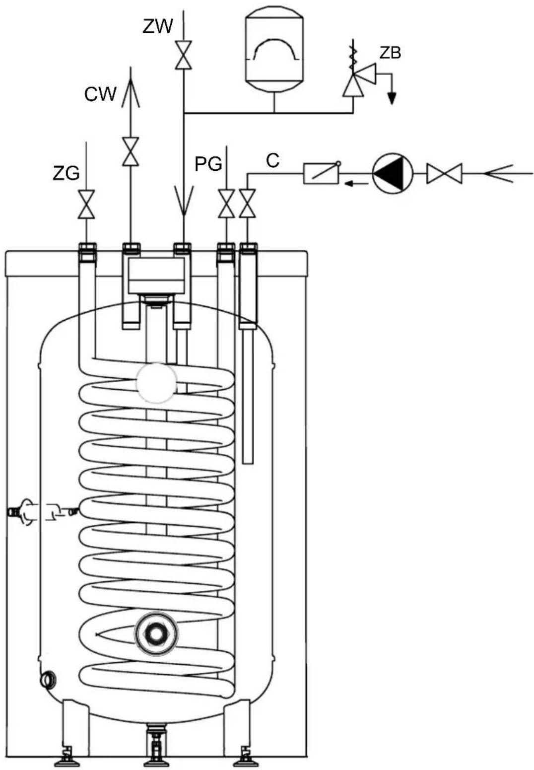
ZW CW ZG PG C ZBConnection with water installation must be performed according to binding norms of hydraulic installation. The cylinder is a pressure appliance designed for connection with water installation where the water pressure doesn't exceed 0,6 MPa. If the water pressure exceeds 0,6 MPa, the pressure reducing valve before cylinder must be fitted. Please follow the water connection instructions below:
- install the T-connection with 6 bar* safety valve to the fitting of cold water inlet [ZW]. It's forbidden to install a cut-off valve (or any flow reducer) between storage and the safety valve and on its outlet. The safety valve must be installed in such a place as to quickly let you notice the outgoing water,
- install the cylinder equipped with the safety valve with water installation,
- install the cut-off valve on cold water supply pipe.
Hot water outlet should be led to the connection 3/4" in the upper part of the cylinder. Every cylinder is equipped with connection 3/4" intended for its installation to the DHW circulation.
*Please note: use the safety valve matched to the heat's source. Installing a safety valve with inadequate capacity can result for excessive pressure increase in the cylinder and as a result a leakage. In this case, warranty does not cover damage caused.
text_image
ZG 3/4" CW 3/4" ZW 3/4" PG 3/4" C3/4" 272mm 100mm 44mm 0 120 173 258 30° 608[1] - upper lid
[2] - thermal insulation
[3] - magnesium anode
[4] - thermometer
[5] - heating coil
[6] - sensor pipe
[7] - draining connection 1/2"
[8] - feet
[9] - anode's blank
[10] - immersion heater connection (cork 1½")
ZW - cold water (PEX-AL-PEX pipe)
CW - hot water
C - circulation
ZG - heating medium supply of coil
PG - heating medium return of coil
A-C - dimensions specified in the diagram
text_image
Ø595 PG CW ZW ZG ZC ① ② ③ ④ ⑤ ⑥ ⑦ ⑧ ⑨ C 10 B A| Dimensions | SWK100 | SWK120 | SWK140 |
| A | 127 | ||
| B | 643 | 705 | 816 |
| C | 906 | 1018 | 1140 |
Before the start-up close the draining connection e.g. by screwing the valve in and make sure that the installation procedures have been carried out in accordance with the regulations included in this manual.
Cylinder must be filled with water:
- turn on the valve on cold water supply pipe.
- turn on the hot water outlet valve (water outflow without the air bubbles indicates that the storage is full),
- turn off the outlet valves.
Turn on the valves connecting cylinder with the central and the solar collector heating system. Check for water and heating medium leaks. Check out the safety valve performance in accordance with valve manufacturer's instruction.
Operation
Follow the guidelines below for safety and trouble-free cylinder operation:
- Check out the safety valve performance once every 14 days. Do not use the cylinder if the water does not come out (it indicates that the valve is broken).
- Clean inside of the cylinder periodically. The frequency of cleaning depends on the degree of water hardness. The cleaning should be done by a qualified person.
• The wear condition of the anode must be inspected annually.
• The anode must be replaced once every 18 months.
- anode rod replacement [3]: take off anode's blank [9], take out an insulation ring, turn off the cut-off valve on cold water supply pipe, turn on the hot water valve (mixer tap), turn the drain valve on, drain as much water as you need to easily unscrew the anode rod (avoiding room flooding). Remove the cork and unscrew the anode rod.
- Heat up the water above 70^ periodically for hygiene reasons.
- Failures or malfunctions notify to the seller.
- Insulate the outlet pipe and heating coil connection pipes to minimise the heat loss (recommended).
Above activities are beyond of the scope of warranty service (should be done by the user).
In order to empty the cylinder:
- turn off the valves which connect cylinder with central heating system,
- turn off the valve on the cold water inlet,
- turn on the drain valve.
Technical data
Domestic Hot Water Cylinder SWK
| Capacity I100120140 | |||||
| Rated pressure | storage | MPa | 0,6 | ||
| coil 1 | |||||
| Rated temperature °C95 | |||||
| Surface area of coil m | ^2 | 0,821,01,1 | |||
| Coil capacity dm | ^3 | 5,36,47 | 6 | ||
| Power of coil kW 25* 7,5** 30* 9** 32* 10** | |||||
| Efficiency of coil | l/h | 625*; 185** | 750*; 225** | 800*; 250** | |
| Weight (without water) | kg | 58 | 65 | 72 | |
| Magnesium anode - service code | 01448 | ||||
| Magnesium anode - product code | AMW.M8 450 | ||||
*80/10/45°C } - heating water temp./ supply water temp./ domestic water temp./ flow rate of **55/10/45°C } - heating water through the coil - 2,5 m³/h.
text_image
ZG 3/4" CW 3/4" ZW 3/4" PG 3/4" C3/4" 272mm 100mm 44mm 0 120 173 258 30° 608[1] - carcasa superior