Santorin 30-500 - Subwoofer CABASSE - Free user manual and instructions
Find the device manual for free Santorin 30-500 CABASSE in PDF.

| Product type | Active subwoofer |
| Brand | Cabasse |
| Model | Santorin 30-500 |
| Speaker driver | 30 cm (model 30ND40) |
| Frequency response | 22 - 200 Hz |
| Rated power | 500 W RMS |
| Peak power | 1000 W |
| Adjustable crossover frequency | 30 - 200 Hz in 1 Hz steps |
| Phase adjustment | 0° - 180° in 1° steps |
| Power supply | 110-120 V / 220-240 V AC, 50/60 Hz |
| Maximum power consumption | 625 W |
| Dimensions (H x W x D) | 43 x 38 x 47 cm |
| Weight | 28 kg |
| Operating temperature | +5°C to +35°C |
| Storage temperature | -5°C to +40°C |
| Relative humidity during operation | 40% to 70% |
| Main features | Front control panel, remote control, 3 presets, 3 parametric filters, automatic adaptation, RCA, high-level and XLR inputs |
| Maintenance and cleaning | Disconnect before cleaning, use a damp cloth |
| Safety | Follow warnings, do not expose to water or excessive heat source |
| Spare parts and repairability | Use parts recommended by the manufacturer, entrust repairs to qualified technician |
| General information | Manual available in multiple languages, free download at notice-facile.com |
Frequently Asked Questions - Santorin 30-500 CABASSE
User questions about Santorin 30-500 CABASSE
0 question about this device. Answer the ones you know or ask your own.
Ask a new question about this device
Download the instructions for your Subwoofer in PDF format for free! Find your manual Santorin 30-500 - CABASSE and take your electronic device back in hand. On this page are published all the documents necessary for the use of your device. Santorin 30-500 by CABASSE.
USER MANUAL Santorin 30-500 CABASSE
natural_image
Abstract interwoven curved lines forming an infinity symbol (no text or symbols present)NOTICE D'INSTALLATION DES CAISSONS DE GRAVES
SUBWOOFER OPERATING INSTRUCTIONS
natural_image
3D rendering of a rectangular electronic device casing with a control panel and base mount (no text or symbols visible)Cabasse
1
2
natural_image
Close-up of a mechanical device with a circular inset showing internal components, no visible text or symbols.FRANÇAIS
ENGLISH
DEUTSCH
4
5
FRANÇAIS
ENGLISH
DEUTSCH
6
INSTRUCTIONS DE SÉCURITÉ
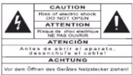
EXPLICATION DES SYMBOLES -
Attention aux chariots de manutention
INSTALLATION SUR MOBILIERS ET SUPPORTS -
$$ \text { CHANNELS } = R + L $$
B) CONFIGURATION 5.1: 5 ENCEINTES + 1 SANTORIN RELIÉS À UN AMPLIFICATEUR AUDIO-VIDÉO.
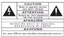
SYMBOLS - The lightning flash with arrowhead symbol, within an equilateral triangle, is intended to
alert you to the presence of unin-
sulated “dangerous voltage” within the product’s enclosure that may be of sufficient magnitude to constitute a risk of electric shock to persons.

The exclamation point within an equilateral triangle is intended to alert you to the presence of important operating and maintenance (servicing) instructions in the literature accompanying the appliance.
INSTRUCTIONS - Carefully read through all the safety and operating instructions before switching on any device for the first time.
KEEP THESE INSTRUCTIONS IN MIND - They will be constantly referred to through this manual.
PAY SPECIAL CARE TO WARNINGS - All the warning labels on the product or warning notes in the user's manual must be followed.
FOLLOW THE INSTRUCTIONS - Follow carefully all the installation and operation instructions.
CLEANING - Always remove the power cord before cleaning the device. Do not use cleaning solvent, whether liquid or air spray. Using a soft damp cloth is recommended.
ACCESSORIES - To avoid incidents, only use accessories expressly recommended by Cabasse.
WATER AND MOISTURE - The product shall not be used in damp or wet locations, such as humid basements, next to a bathtub, sink, swimming pool or any other similar conditions.

CARTS AND STANDS - The appliance should be used only with a cart or stand that is recommended by the manufacturer.
Portable cart warning
INSTALLATION ON A PIECE OF FURNITURE AND STANDS - Do not place this device on an unsteady surface, i.e. a stand, tripod, table, shelf, etc. It may fall and cause serious injury to a nearby child or adult.
VENTILATION OUTLETS - The device shall not be placed in a position that restrains the operation of its fans. Avoid installing the device on a bed, couch, blanket or other similar surfaces that may prevent the appropriate air flow. Do not install the device in a confined space, such as a book shelf or other piece of furniture, that could prevent sufficient air from flowing freely.
POWER - The device shall only be connected to a source of power compliant to the one described in this manual or on relevant printed labels on the product. If you are not sure of the type of power available, please contact your reseller or the local power company.
POWER CORDS - The power cords must be laid out in such a way that they cannot be walked on, pinched, bent under other devices. Also pay special attention to the matching of the plugs and the connection of the cord to the device.
PLASTIC BAGS - Keep them away from children to prevent any risk of suffocation.
LIGHTNING - For better protection against lightning or if the device must remain unused for long stretches of time, unplug the power cord and antenna jack. This minimizes potential damages due to lightning or line surges.
OVERLOADS - Avoid overloading the power plugs, extension cords or power relays. This could result in fire or electric shocks.
FOREIGN BODIES AND LIQUIDS - Avoid letting foreign materials or liquids enter the device. They could cause fire or electric shocks. Never spill any liquid on the device.
MAINTENANCE - Users must never attempt to maintain the device on their own, except for those maintenance operations described in this manual. Any task beyond regular user maintenance must be performed by qualified service operators.
TROUBLESHOOTING - You must unplug your device from the power supply and have it checked by a qualified technician if:
■ The power supply or the plug is damaged.
■ Foreign bodies or liquid penetrated the device.
■ The device was exposed to dripping or splashing.
The device does not seem to work correctly under normal operating conditions. Only operate the controls described in this manual. Any other operation could damage the device and require on-site visit of a qualified technician.
■ The device has fallen or its housing is damaged.
■ The performances of the device are strongly altered.
SPARE PARTS - If spare parts are needed to repair the device, make sure that the technician followed the manufacturer's recommendations or that the replacement parts feature the same specifications as the original ones. Non-compliant parts can result in multiple damages, including fire or electric shocks.
CHECKS - After any servicing of the device, ask the technician to perform appropriate testing to make sure that the device works safely.
EXPOSURE TO HIGH TEMPERATURES - The device should be kept away from heating sources, such as radiators, heaters, amplifiers or any other similar item likely to make the operating temperature rise excessively.
Applicable for USA, Canada or where approved for usage
Caution! To prevent electric shock, match wide blade plug to wide slot, insert fully.
UNPACKING SANTORIN 30-500
The packing includes one Santorin 30-500 subwoofer, a set of 4 decoupling cones, a power cable, the guarantee card, the owner's manual, a measurement microphone and a microphone table stand. After opening the top carton flaps, fold them right back and invert the carton contents. Lift the carton clear of the contents and remove the inner packaging from the speaker. We suggest you to retain the packing for future use.

This speaker is heavy therefore 2 people are required to unpack it.
POSITIONING
SPEAKER POSITIONING
Our speakers have been designed to function in a vertical position. The majority of our models are delivered with a set of decoupling spikes or cones, these accessories are to be screwed in the inserts under the cabinets. These accessories ensure the stability of the speaker while limiting resonance coming from cer-
tain types of grounds like wood floors.
Powerful drivers generate magnetic fields that can extend beyond the boundaries of the speaker cabinet. We recommend you keep magnetically sensitive articles (TV, computer screen, computer discs, audio and video tapes, swipe cards...) at least 1.5 ft (50 cm) away from the speaker. Cabasse centre speakers or the ones marked «TV» are not concerned with this, being magnetically shielded.
POSITIONING SPEAKERS IN A ROOM
OPTIMAL POSITIONING FOR A 2.1 OR STEREO WITH A SUBWOOFER SYSTEM
For a stereo listening with 2 speakers or 2 satellites and 1 subwoofer, we recommend you to place the subwoofer in the front listening area. The placement of the subwoofer against a wall reinforces the low frequencies and limit the reflections from 80 to 200 Hz. However to obtain the best results, it is always necessary to carry out tests according to the acoustic of the room.
OPTIMAL POSITIONING FOR A 5.1 OR HOME THEATRE SYSTEM
Setting up a multi-channel Audio-Video system requires great care when positioning the specific AV speakers.
The centre speaker should be placed as close as possible to the screen and where it sounds best from your listening spot while offering the optimal picture/dialogue cohesion. Theoretically, the screen should be located within a virtual triangle formed by the acoustical centres of the main speakers and the centre speaker. Practically speaking, this means that the principal speaker should be placed above the screen if the main speakers are below it, and below the screen if the main speakers are above. The centre speaker should also, if possible, be set slightly back from the others, so that it is located at the same distance from the listener as the main speakers.
The rear speakers or surround should be placed against the side walls, at listening height. They should not be positioned far behind the listening zone.
The subwoofer should be placed in the front listening area, its position against a wall reinforces the extreme low register and limits the reflections between 80 and 200 Hz. However to obtain the best result, it is always necessary to carry out tests according to the acoustics of the room. Your AV processor enables the adjustment in level and delay of each of the 5/6/7 channels of your system. Fine-tuning is necessary to obtain a perfect sound stage. Turn off all the amplifiers before connecting them to the loudspeakers. In order to connect loudspeakers properly, it is most important to keep in mind the following two factors: cable section and phase.
CONNECTION
CABLE SECTION
To get the full sonic potential of Cabasse loudspeakers and avoid power losses, the cables connecting the speakers to the power amplifier must have the lowest possible electrical resistance. To help you in choosing the correct cable gauge, follow diagram.
| Length between amplifier and loudspeakers | recommended section |
| 4,5 m | 1,5 mm^2 |
| 6 m | 2 mm^2 |
| 7,5 m | 2,5 mm^2 |
| 9 m | 3 mm^2 |
| 12 m | 4 mm^2 |
PHASE
In order to maintain the phase relationship and frequency balance of the loudspeaker system, both loudspeakers must be properly connected to the power amplifier. When properly connected, the cones of the drivers of both loudspeakers will move in the same direction when driven by the same signals. If the cones move in opposite directions, the resulting out of phase signals will create a perceptible power loss, particularly in the low frequencies. The stereophonic message will also be degraded.
Amplifier and speaker manufacturers typically indicate connection polarity in one of two ways: red and black or plus and minus. In either case, always connect red or plus to red or plus and black or minus to black or minus. Connections should be identical for both channels. To check that the speakers are in correct phase, switch the system to mono while music is being played. If the amplifier does not have a phase inversion switch, it will be necessary to change over the connections on one only of the loudspeakers. If in correct phase, the image should be distinctly located between the loudspeakers with a slight loss of bass and low midrange level. If the image is confused and not centrally located and there is a drastic loss of bass and low midrange level, recheck your connections.
POWER MANAGEMENT
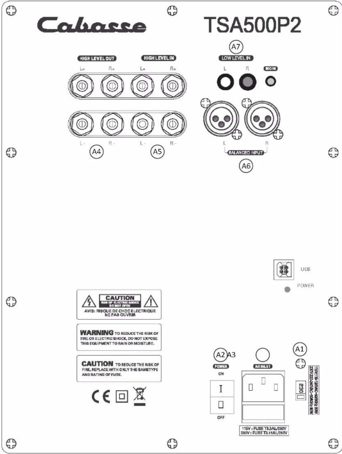
Select the right voltage with the 115 V – 230 V A1 switch and connect the A3 plug to the mains with a 700 W or more power chord cable (3 A / 230 V, 6 A / 115 V). Then power on the amplifier with the A2 switch. Finally press the POWER key of the remote control or any key on the front pad to get the system on play mode. The display will be activated after 3 to 4 seconds.

Attention, before operating the unit, be sure that the operating voltage of your unit is identical with that of your local power voltage.
SETTINGS
I) THE AJUSTABLE PARAMETERS
USE OF THE FRONT PANEL PAD :
The 5 keys on the front panels of the Santorin give access to all the here-under adjustable parameters.
Use the “←” and “→” (TP6 et TP3) keys to select the parameters, then select the right option or value thanks to the “↓” et “↑” (TP4 et TP2) keys. The “ENTER” (TP1) key must be pressed down to confirm a setting and/or answer to “ENTER ?” and “VALIDATE ?”.
A) PARAMETERS ADJUSTABLE ONLY BY MEAN OF THE FRONT PANEL :
SOURCE: selection of the type of input/output being used : - RCA+HL: RCA "LOW LEVEL INPUTS" (A7) inputs and « HIGH LEVEL INPUTS » ( A5 speaker cable terminals). These 2 types of inputs can be used simultaneously depending on configuration.
- XLR: XLR A6 inputs
■ CHANNELS: selection of the input channels being used :
- R: right channel
- L: left channel
- R+L: right and left channels
VOLUME: adjustment of the subwoofer sound level, -30 dB to +6 dB, pressing the "+" and "-" keys in 1 dB increments.
- LOW PASS FILTER: adjustment of the subwoofer's low-pass frequency, 30 Hz to 200 Hz, pressing the "+" and "-" keys in 1 dB increments.
PHASE: setting of phase of the subwoofer output signal, 0 to 180 degrees, pressing the "+" and "-" keys in 1 dB increments.
AUTO ACQUISITION: automatic setting of the subwoofer parametric filters. It requires the use of the microphone and the microphone preamplifier delivered with the Santorin.
PARAMETRIC 1 – PARAMETRIC 2 – PARAMETRIC 3: these 3 parametric modules allow the room adaptation of the subwoofer response in order to decrease the acoustical defaults of the listening room in low frequencies. They can either be activated manually or with the AUTO ACQUISITION process.
The manual setting implies the adjustment of the following parameters listed in the "PARAMETRIC 1 – PARAMETRIC 2 – PARAMETRIC 3" sections:
- CENTER: it determines the middle frequency of the correction: it is adjustable between 30 and 200 Hz in 1 dB increments.
- BAND WIDTH: width of the correction, from 1/8 of an octave up to 2 (16/8) octaves in 1/8 of an octave increments.
- GAIN: intensity of the correction, adjustable from -12 dB to +4 dB in 1 dB increments.
POWER: Power management - ON: the subwoofer is ready for activation either by pressing down the "POWER" key on the remote control or by pressing down any key of the front panel.
OFF: the subwoofer is no longer activated. Activation requires to position the POWER section on "ON" or "AUTO"
AUTO: automatic power management with activation of the subwoofer when audio signal is received by the subwoofer. This is the setting we advise to be used after the correct setup has been achieved. The remote control can be stored until new setting becomes necessary.
■ DELAY: compensation of the time delay when the subwoofer is placed between the listening spot and the main speakers. It is adjustable between 0 and 6.8 meters in 0.34 meter increments.
B) PARAMETERS ADJUSTABLE WITH THE FRONT PANNEL AND/OR THE REMOTE CONTROL:
■ POWER: on and off switch of the subwoofer
MUTE:
- MUTE ON: the sound signal is cut off, the subwoofer remains powered and all the parameters can be adjusted.
- MUTE OFF: the subwoofer is on play mode.
■ PRESET 1, PRESET 2, PRESET 3: access to the end-user presets.
- DISPLAY: Screen display: press this key to switch on or off the LCD display.
REMOTE CONTROL KEYBOARD:
■ POWER (RC1): subwoofer's power switch
MUTE (RC2):
- MUTE ON: the sound signal is cut off, the subwoofer remains powered and all the parameters can be adjusted.
- MUTE OFF: the subwoofer is on play mode.
■ PRESET 1, PRESET 2, PRESET 3 (RC4, RC5, RC6): activation of the enduser presets.
- DISPLAY (RC7): Screen display: press this key to switch on or off the LCD display.
II) CONNECTIONS AND CONFIGURATION:
Santorin 30-500 has been designed for optimum results in almost every audio and video application. These are the instructions for the main domestic configurations:
A) 2.1 CONFIGURATION: 2 satellites + 1 Santorin connected to a stereo amplifier.
Connect the right (R) and left (L) HI LEVEL inputs A5 of the Santorin to the loudspeakers' output terminals of your amplifier with loudspeaker cable. Be careful not to invert polarity and/or channels, the red (+) terminals of the amplifier must be connected to the red (+) terminals of the amplifier, and right amplifier's output to the right inputs of the subwoofer.
Connect the right (R) and left (L) HI LEVEL outputs A4 of the Santorin to the terminals of both satellite speakers. Respect polarities and left and right when connecting the speaker cable between the subwoofer and the satellites.
Connect the Santorin to the mains and power it on.
Set the « SOURCE » and « CHANNELS » parameters as follow: SOURCE = RCA + HL CHANNELS = R+L
B) 5.1 CONFIGURATION: 5 loudspeakers + 1 Santorin connected to an AV-amplifier.
Connect either the right(R) or the left (L) LOW LEVEL INPUT (A7) of the subwoofer to the SUBWOOFER / LFE output with an RCA/RCA cable. If the amplifier or preamplifier is also fitted with a XLR output for SUBWOOFER/LFE we advise to choose it and connect it to one of the (A6) BALANCED INPUTS of the Santorin.
Connect the Santorin to the mains and power it on.
■ SOURCE = RCA + HL or XLR if BALANCED INPUT is being used
■ CHANNELS = R or L

Attention
The subwoofer might hum in such a configuration, depending on the ground specs of the other components. If so, the problem is cancelled by joining the electrical grounds of the subwoofer and the preamplifier with a RCA-RCA cable connected to one of the RCA inputs of the subwoofer and to one available RCA input of the preamplifier.
III) SANTORIN SET-UP PROCEDURE
Once the above connections have been fully done and the subwoofer connected to the mains and switched on and activated with the "POWER" of the remote control or any of the front keys, proceed to the following set-ups using the front panel of the subwoofer.
A) SELECTION OF THE SOURCE: check in « SOURCE » that the inputs and outputs being listed are the ones being used:
■ RCA+HL : RCA INPUTS and/or HI-LEVEL INPUTS/OUTPUTS
■ XLR : XLR BALANCED INPUTS2)
B) INPUT CHANNEL SELECTION: check in « CHANNELS » the channel(s) being used:
a) R: Right channel
b) L: Left channel
c) R+L: both Left and Right channels
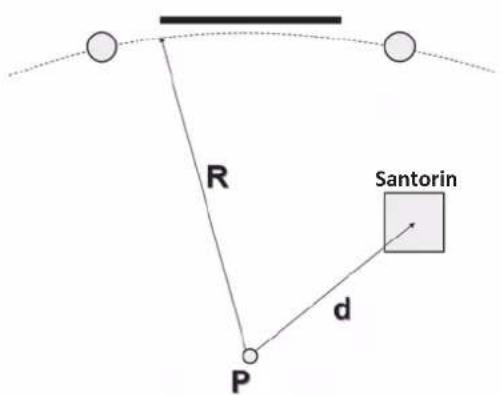
C) DELAY SET-UP: if the subwoofer is placed between the main speakers and the listening spot or at a shorter distance to the listening spot than the main speakers, the adjustment of the DELAY will improve the sound result by entering in DELAY the difference between two distances.
The distance d1 is the radius of the circle passing by both main speakers tweeters, the listening spot being its centre, d2 being the distance between the sweet spot and the subwoofer ((4) scheme). The result r= d1- d2 is the value to enter in the DELAY section if positive. If d2 is higher than d1, then leave DELAY on "0" and go to the PHASE SECTION for precise setting.
D) SELECTION OF THE LOW PASS FILTER FREQUENCY
The upper limit of the subwoofer's frequency depends upon the type of use of the subwoofer, the main speakers' characteristics and the setting possibilities offered by the AV-amplifier involved in the system: 5.1, 6.1, 7.1 set-up for single LFE channel reproduction with full range speakers for the other channels. The LFE channel is monitored by the processor of the AV amplifier, we therefore advise to set the low-pass filter of the Santorin on 200 Hz to avoid overlapping of both filters.
- iO2 : 125 Hz
- Minorca / Minorca IW : 60 Hz
- Riga : 80 Hz
- Bora : 55 Hz
- Baltic Evolution : 65 Hz
- Altura IW : 45 Hz
- Murano : 50 Hz
Multichannel set-up with satellites speakers requiring back-up of a subwoofer for reproduction of the bottom-end frequencies: adjust the lowpass filter of the Santorin on 200 Hz, then go in the SET-UP menu of the AV amplifier, set the speaker sizes on SMALL when required and set the cross-over frequency between subwoofer and satellites speakers as close as possible to the characteristics of each satellite. Regarding Cabasse speakers, select the frequency in the above table. If not listed here, this frequency is available on the spec sheets of the products and on : www.cabasse.com
When the SET-UP menu allows only one cross-over frequency and satellites with different roll-off frequencies are being used, then select the highest frequency.
Stereo use with a stereo amplifier:
In this configuration the subwoofer and a pair of Cabasse satellites speakers are connected to a stereo amplifier. Select the low pass frequency in the above table and enter it into the set-up menu of the subwoofer.
An experienced installer will be able to select after measurements on site other values than the ones we determined in our anechoic chamber, taking into account the acoustical specifications of the listening room.
E) VOLUME ADJUSTMENT: when the set-up includes satellite speakers, we recommend to first adjust the volume between the subwoofer and the main speakers in stereo mode with a selection of music rich in low frequencies. Once this set-up is achieved, adjust the LFE level in the set-up menu of the AV amplifier. Further LFE levels adjustments should be done in the AV amplifier and not in the subwoofer software.
F) PHASE ADJUSTMENT: it allows if necessary to flatten the frequency response around the cross-over point. If the subwoofer is closer to the listening point than the main speakers, then leave the PHASE on the 0° and adjust the DELAY. The right setting is
the one giving the highest perceived level of low frequencies. Try first 0°, then 180° and 90°. Other values should be used by experienced installers with the help of measuring equipment. Readjust the phase each time you move the subwoofer or the main speakers and each time you select a new cross-over frequency.
G) PARAMETRIC FILTERS:
Thanks to our long experience in digital sound processing, we have developed for the Santorin 30-500 unique room corrections modules. When a graphic filter proposes volume adjustments on fixed bandwidth, our parametric filters offer more precise and more natural settings, being perfectly focused on the critical zones. Sometimes the room acoustic requires the use of only one parametric filter where a graphic filter will in any case be active all along the bandwidth of the subwoofer and create phasing shifts.
G1) AUTOMATIC ROOM EQUALISATION (5) (6):
1) Check that all the above settings are done and recorded.
2) Select « PRESET 2 » for the first adjustment in order to keep « PRESET 1 » as a reference.
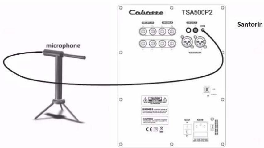
3) Unpack the microphone and the mic-stand delivered with the subwoofer.
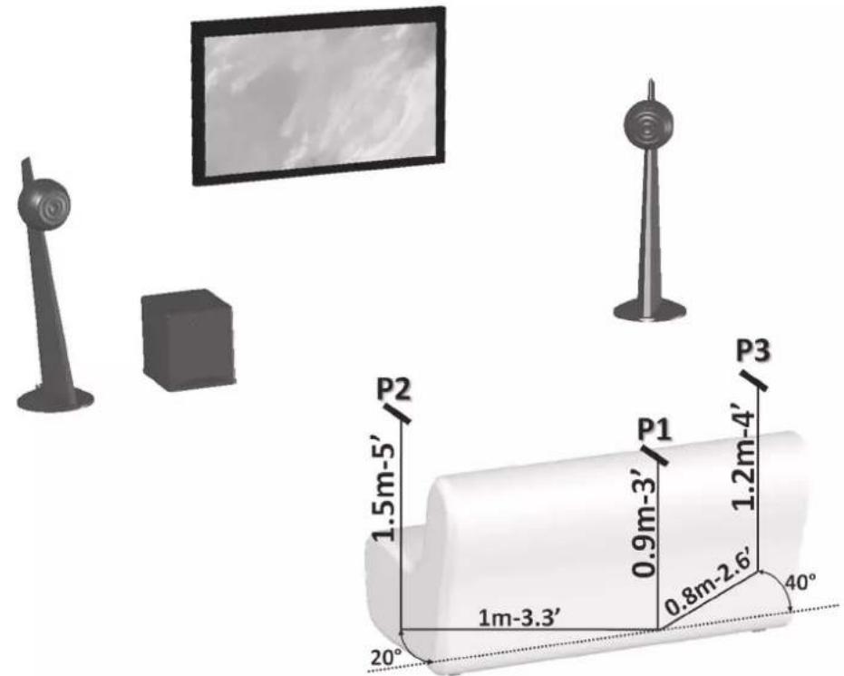
4) Place the microphone at the height of the listening point (P1 on drawing (6)) and connect it to the microphone-preamplifier input "MIC IN".
5) In the subwoofer set-up:
a. In «AUTO ACQUISITION», press enter to confirm the measurement process.
b1. Check that the microphone is right at the height of the listening spot (P1).
b2. Press « ENTER » to launch the measurements acquisition 1.

If « no signal input » comes out on the LCD screen, check all the connections and above setups and start "AUTO ACQUISITION" again.
c1. Place the microphone around 1 m aside the (P1) position (left or right, as for as possible from the walls), somehow in front of (P1) and around 60 cm above initial position (P2).
c2. Press « ENTER » to launch the measurements acquisition 2.
d1. Place the microphone around 60 cm away from (P1) position, opposite side of (P2), somehow in front of (P2) and around 60 cm above initial position (P3).
d2. Press « ENTER » to launch the measurements acquisition 3.
e. «Finished!»: the automatic room compensation is achieved. Validate the recording for the selected PRESET with "OK". It is then possible to record other compensations in another PRESET with other microphone positions. Before starting listening tests: Select « XLR» as « SOURCE » if necessary and unplug the microphone preamplifier from the subwoofer. Check and if necessary set the "VOLUME" of the subwoofer, as the EQprocess might have modified the sound level around the low-pass frequency. Unplug and store carefully the measurement equipment for eventual further use after having completed the set-up of the subwoofer.
G2) MANUAL ROOM EQUALISATION:
This way of setting up might bring better results than the Cabasse autocalibration system only if skilled people with specific measurement equipment are involved. It can also be used to slightly modify some auto-calibration values for audio comparisons of different PRESETS ((RC6) keys) or use of sources with different sound balances.
1) Select PRESET (1, 2 or 3).
2) Use the « ← » and « → » keys (TP6 et TP3) of the control pad, then « ENTER » to select one of the parametric modules: PARAMETRIC 1, PARAMETRIC 2, PARAMETRIC 3.
3) « CENTER »: choose the middle frequency of the bandwidth to be modified, between 30 and 200 Hz in 1 Hz increments.
4) « BAND »: select the width of the correction, from 1/8 of an octave up to 2 (16/8) octaves in 1/8 of an octave increments.
5) GAIN: adjust intensity of the correction, adjustable from -12 dB to +4 dB in 1 dB increments.
6) Validate the above 3 values: press the ENTER key (P1) on « EXIT ».
7) Proceed the same way for the other parametric modules if they are to be used.
H) USE OF PRESET1, PRESET2, PRESET3:
The factory setup is with PRESET 1 on. The gains of the 3 parametric modules are set on 0 dB, bandwidth being on 1 Octave. The frequencies are preset on 50 Hz for PARA 1, 60 Hz for PARA 2, 70 Hz for PARA 3.
1) Recording of a PRESET: it is fully automatic, any new modification of a parametric module is immediately recorded in the last selected PRESET.
2) Access to the PRESETS:
- Direct access with the PRESET1, PRESET2, and PRESET 3 keys of the remote control.
- In the menu of the control pad: select « PRESET » with the « ← » et « → » keys (TP6 et TP3) then PRESET1, PRESET2, or PRESET 3 with the « ↓ » and « ↑ » keys (TP4 et TP2).
I) DISPLAY MODE
Press the « DISPLAY » key on the remote to control to get the display "ON" or "OFF". The display mode can also be modified in the setup menu using the keypad of the subwoofer.
Because of technical improvements already under way in our constant search for optimum quality, Cabasse reserves the right to modify all the models presented in specification sheets, advertising materials and manuals without prior notice.
Battery replacement: take the remote control in your hand with the key side facing the floor. Press the locker and pull out the battery-tray (picture 3a). Remove the dead battery and replace it with another 3V lithium one, type CR2025. Dispose of the old battery according to these instructions.
Disposal of battery packs / batteries
Do not dispose of battery pack/batteries into house hold waste, fire or water. Battery packs/batteries should be collected, recycled or disposed of in an environmental friendly manner.

Only for EC countries:
Defective or dead out battery packs/batteries must be recycled according the guideline 91/157/EEC. For more detailed information about recycling of this product, please contact your local city office, your household waste disposal service or the shop where you purchased the product.
| Santorin 30 - 500 | |
| Active subwoofer 30 cm ø - model 30ND40 | |
| Frequency response 22-200 Hz in semi-reverberating chamber | |
| Maximum sound pressure level 111 dB RMS | |
| Maximum output power 500 W RMS | |
| Peak power 1000 W | |
| Lowpass cut-off frequency from 30 to 200 Hz in 1 Hz increments | |
| Phase adjustment 0° to 180° in 1° increments | |
| Power requirements 110-120V / 220-240V AC - 50 / 60 Hz | |
| Maximum power consumption 625 W | |
| Dimensions (h x w x d) | 43 x 38 x 47 cm17 x 15 x 18.5 in |
| Weight 28 kg - 62 lbs | |
| Useable temperature range +5°C to +35°C | |
| Storage temperature -5°C to +40°C | |
| Useable humidity range 40% to 70% | |
ENGLISH
SICHERHEITSHINWEISE
SOURCE = RCA + HL
CHANNELS = R+L
natural_image
Abstract black line drawing of intertwined loops (no text or symbols)Cabasse
Cabasse SA - 210, rue René Descartes - BP 10 - 29280 Plouzané
Tel +33 (0)2 98 05 88 88 - Fax +33 (0)2 98 05 88 99
www.cabasse.com