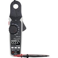
MS-18/2 - Multimeter VOLTCRAFT - Free user manual and instructions
Find the device manual for free MS-18/2 VOLTCRAFT in PDF.
| Product type | Multi-tester (specialized multimeter) |
| Brand | Voltcraft |
| Model | MS-18/2 |
| Power supply | 3 V (2 button cells 1.5 V type 392A, AG3, LR41, 192) |
| AC voltage detection (direct contact) | 70 to 250 V AC |
| AC voltage detection (non-contact) | 70 to 500 V AC |
| Polarity determination for DC voltage | 1.2 to 35 V DC |
| Electrical continuity test | 0 to 50 MΩ |
| Microwave leakage detection | > 5 mW/cm² |
| Frequency range | 50 to 500 Hz |
| Operating temperature | -10 °C to +50 °C |
| Protection class | 2 (double insulation) |
| Overvoltage category | CAT II |
| Main functions | AC voltage detection (direct/non-contact), polarity determination, electrical continuity test, microwave leakage detection, self-test |
| Display | Red LED indicator with temporary memory (0.5 to 2 s) |
| Maintenance and cleaning | Disconnect from any voltage source before maintenance. Clean with a soft, dry cloth. Do not use liquids or detergents. |
| Safety | Do not exceed max input values. Use only in dry indoor environments. Check before each use. Do not use if damaged. |
| Spare parts and repairability | Button cells type 392A, AG3, LR41, 192. Repair only by a specialist. |
| Package contents | Multi-tester, 2 button cells, instruction manual |
| General information | Conforms to European directives. Use only in dry environment. Do not use as a screwdriver. |
Frequently Asked Questions - MS-18/2 VOLTCRAFT
User questions about MS-18/2 VOLTCRAFT
0 question about this device. Answer the ones you know or ask your own.
Ask a new question about this device
Download the instructions for your Multimeter in PDF format for free! Find your manual MS-18/2 - VOLTCRAFT and take your electronic device back in hand. On this page are published all the documents necessary for the use of your device. MS-18/2 by VOLTCRAFT.
USER MANUAL MS-18/2 VOLTCRAFT
flowchart
graph LR
    A["Rectangular Block"] --> B["Rectangular Block"]
    B --> C["Rectangular Block"]
    C --> D["Rectangular Block"]


natural_image
Close-up of hands holding a tool with a black object, no visible text or symbolsnatural_image
Hand inserting a plug into a socket (no text or symbols visible)natural_image
Close-up of hands holding a small electronic component with wires (no visible text or symbols)natural_image
Close-up of hands holding a small bottle with a pipette tip, no visible text or symbolsPraxis-Hinweis!
- Introduction....12
- Explanation of symbols....12
- Intended use....12
- Product description....13
- Delivery content....13
- Safety instructions .... 14
- Description of individual components 14
- Operation....15
a) Inserting the battery / Changing of battery 15
b) Self-test 15
c) Alternating voltage detection 16
d) Direct voltage test (1.2 to 35 VDC)....16
e) Continuity check 0 - 5 MOhm (direct contact)....17
f) Practice note!......17
g) Microwave leak test ( >5 mW/cm^2 )....17
-
Maintenance and care 17
-
Disposal....18
a) General....18
b) Disposal of spent rechargeable batteries 18
- Technical data....18
1. Introduction
Dear customer,
Thank you for your purchasing the multitester.
With this product you have bought a state of the art product. This product satisfies the standards of the established European and national guidelines. CE-conformity has been proven, the relevant documents are in the manufacturer's possession. We kindly request the user to respect this operating manual to preserve this condition and to ensure safe operation.
If there are any technical questions, please contact:
www.conrad.com/contact
2. Explanation of symbols

The symbol with the exclamation mark in the triangle is used to indicate important information in these operating instructions. Always read this information carefully.

The arrow symbol indicates special information and advice on operation.
3. Intended use
The agreed upon use of the device covers:
- Testing of alternating voltage:
- direct measuring 70 - 250 V AC
-
indirect measuring 70 – 500 V AC
-
Polarity check 1.2 V to 36 V DC (direct voltage)
• Continuity check approx. 0 to 5 MOhm - Testing of microwaves and televisions for radiant emittance
- Use only in dry environment

Any use other than the one previously described can lead to damages on the product. Moreover, this involves dangers, such as e.g., short-circuit, fire, electric shock, etc. No part of the product may be modified or rebuilt and the housing must not be opened.
Always observe the safety instructions and technical data.
4. Product description
The multitester MS18-2 is the further technical development of the successful MS 18. Next to the functions of the MS-18 the MS 18-2 has also been equipped with power saving measuring electronics, through which the current consumption could be lowered by 70 percent. MS18-2 furthermore has a temporary memory function which delays the LED display a further 0.5 to 2 seconds in order to achieve precise and definite measuring results.
With the MS 18-2 you can check voltage-carrying electric lines and part, whether alternating voltage is applied. This can be carried out either with direct contact or contactless (indirect). The indirect measuring can be especially helpful with insulated lines and parts. Moreover, the polarity of direct voltage sources can be determined. When using the device as a continuity tester for circuit track conductors, chassis earth connections, fuses, power cords, light bulbs, switches and many more can be tested on their function (continuity) when off circuit. A further area of use is the testing of components such as diodes, rectifiers, condensers, transistors (NPN/PNP), coils, etc. but also the testing of microwaves for leakage. The display is via a built-in red LED.
5. Delivery content
- Multitester MS 18-2
- two round cell batteries
- Operating instructions
Up-to-date operating instructions
Download the latest operating instructions via the link www.conrad.com/downloads or scan the QR code. Follow the instructions on the website.

6. Safety instructions

In the case of any damages which are caused due to failure to observe these operating instructions, the guarantee will expire. We do not assume liability for resulting damages.
An exclamation mark inside a triangle points to important notes in the operating manual. Please read through the entire manual before putting the device into operation.
- The unauthorised conversion and/or modification of the MS18-2 is not permitted because of safety and approval reasons.
- Never exceed the maximum input quantities.
- A reliable display is only ensured at a temperature range of -10^ to +50^ and a frequency range of 50Hz to 500Hz . The tester is only authorized for the use in closed and dry rooms.
- Avoid all contact to dampness
- Never use the tester if there are any visible damages. Before each use the device needs to be checked if it works correctly.
- In commercial and industrial facilities the regulations for the prevention of accidents of laid down by the professional trade association for electrical equipment and devices need to be observed.
- Static electricity e.g., caused by strong rubbing on the plastic housing, can falsify the reading.
- This tester should be kept out of reach of children.
- The multitester is not suitable to be used as a screwdriver. Be especially careful with voltages larger than 25 V AC or 35 V DC. With voltages like this you can already suffer a life-threatening electric shock.
- This tester can only be used in electrical circuits which are protected with 10A (and/or no capacities larger than 4000VA appear). In the case of any queries which could not be answered by these operating instructions, please a consult specialist or contact our customer service by phone.
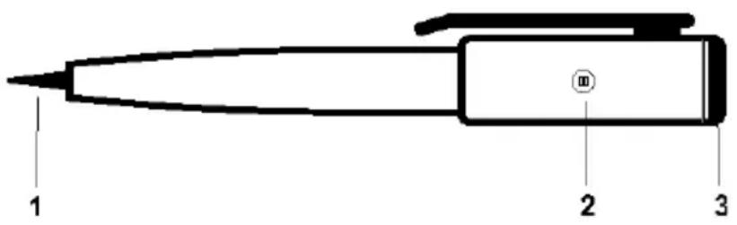
7. Description of individual components
1 Measuring tip
2 LED display
3 Battery compartment lid
text_image
1 2 3a) Inserting the battery / Changing of battery
To operate the multitester two round cell batteries type 392A, AG3, LR41, 192 (or identically constructed) are needed.

To avoid an electric shock the multitester must not be operated when open. After each battery change a self-test needs to be carried out.
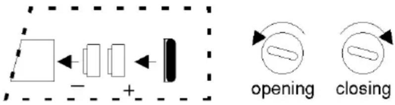
To change the batteries you need to:
- Open the battery compartment at the end of the grip with a suitable screwdriver (3). Opening = turn left (anti-clockwise). Also see illustration below.
• Take out the battery compartment lid (3). Carefully bend back the wire clip which holds the round cell batteries. - Now take out the empty round cell batteries and replace them with two new others of the same type. Take care to observe the polarity of the round cell batteries.
flowchart
graph LR
    A["Input"] --> B["Processing"]
    B --> C["Output"]
    subgraph 'opening'
        D["Process Step 1"]
        E["Process Step 2"]
        F["Process Step 3"]
    end
    subgraph 'closing'
        G["Process Step 4"]
        H["Process Step 5"]
    end
- Carefully bend back the wire in its original position.
- Put the screw back into the device. Carefully tighten the screw. Closing = turn right (clockwise).

Do not let batteries lie around openly. There is the risk of batteries being swallowed by children. In such case, seek instant medical care. Do not let batteries lie around openly. There is the risk of batteries being swallowed by children. In such case, seek instant medical care. Leaking or damaged batteries might cause acid burns when getting into contact with skin, therefore use suitable protective gloves. Never try to recharge batteries. Do not throw batteries into fire.
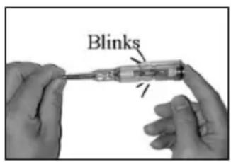
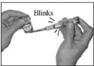
b) Self-test
To avoid wrong readings, the operability of the multitester needs to be checked by a self-test before each use and after each change of batteries. Please check the device for damage(s) such as e.g., breaks on the housing etc.
Touch the tip (1) of the tester with one hand and at the same time touch the battery compartment lid (3) with the other hand.
When the red LED (2) starts blinking, the multitester is in working order and can be used.
In case the red LED does not blink, the device must not be used. If necessary change the batteries.
text_image
Blinksc) Alternating voltage detection
Direct contact (70 to 250 V alternating voltage)
Touch the electric conductor (phase) with the measuring tip (1). If the LED (2) lights up, there is voltage.

During this test the battery compartment lid must not be touched with the finger.
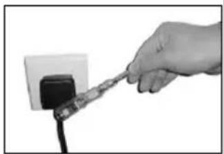
Indirect contact (70 to 500 V alternating voltage)

During this test the tip of the tester must not touch the tested line (device) directly.
Please note that the LED (2) only goes out after approx. 0.5 to 2 seconds after removing the device from the voltage because of the temporary memory function.
Guide the measuring tip of the MS18-2 along an electric cable, electrical outlet or the device.
If there is voltage, (plug in socket, device switched on, etc.) the LED (2) starts blinking. In this way e.g., interruptions in cables etc. can be detected simply and quickly.
natural_image
Close-up of hands holding a tool with a black object, possibly a tool or device (no visible text or symbols)
To increase the sensitivity, the battery compartment lid can be touched with the finger.
This test can not be carried out with shielded cables.
To carry out a quick test on electrical outlets, power supply units or PVC insulated cables hold the MS18-2 on the measuring tip (1) and guide the grip near the device to be tested.
If there is voltage, the LED (2) will start blinking.
natural_image
Hand inserting a cable into a power outlet (no text or symbols visible)d) Direct voltage test (1.2 to 35 VDC)
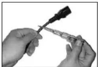
With this function the MS18-2 identifies the polarity of direct voltage sources such as batteries, rechargeable batteries, etc. Touch the pole of the battery to be tested with one finger. Touch the other pole of the battery with the measuring tip (1) (touch battery compartment lid).
If the LED (2) starts to light up or blink, the pole with which the measuring tip is connected, is the positive pole. If the LED stays dark, touch the minus pole.
„+“ Pole, LED light up or blink „-“ Pole, LED dark
text_image
Blinks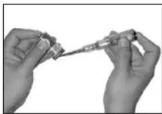
natural_image
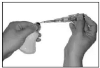
Close-up of hands holding a small object with a tool, possibly a pen or tool, against a plain background (no text or symbols visible)e) Continuity check 0 - 5 MOhm (direct contact)
Touch the battery compartment lid (3) with one hand and with the other hand the contact of the component to be tested (e.g., light bulb). Guide the tip of the multitester to another contact. If the LED (2) starts to light up or blink, continuity is given and the light bulb is in working order. The multitester recognises resistances up to 50 MOhm. With this function you can test fuses, resistances, (up to 50 MOhm), heating elements, electrical components such as condensers, transistors, diodes, coils, etc. simply and easily.
natural_image
Close-up of two hands holding a syringe and a small container (no text or symbols visible)f) Practice note!
- A diode is in working order if the LED starts to light up or blink in conducting direction (finger on cathode, test tip on anode), the LED remains dark in reverse direction.
- A NPN transistor is in working order if the LED starts to light up or blink as soon as the test tip of the emitter or the collector gets touched while the finger taps the base at the same time.
- A PNP transistor is in working order if the LED starts to light up or blink as soon as the test tip on the base is touched while at the same time tapping the emitter or the collector with the finger.
g) Microwave leak test ( > 5 mW/cm^2 )

Caution!
wave radiation is dangerous. This tester can not be compared with a high-tech device. The cost for measuring devices like this are much larger. This is why you should see this test only as an indication for possibly existing microwave radiation.
- Switch your microwave on
- Touch the battery compartment lid (3) with one hand and guide the test tip of the multitester slowly along the door of the microwave. If the door seal is leaky, the LED will start blinking. If this is the case, the microwave must not be operated anymore. Take the device to a specialist.
9. Maintenance and care
Separate the multitester from all power supplies before cleaning it or carrying out maintenance. To clean the outside, only use a soft, dry cleaning cloth. Do not get is damp or use cleaning agents. Maintenance or repairs may only be carried out by an expert who is familiar with the relevant regulations (VDE 100, VDE 0701) (VDE mark of conformity).
10. Disposal
a) General
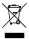
The product must not be disposed in the household waste.
Dispose of the product at the end of its serviceable life in accordance with the current statutory requirements; e.g., return it to any suitable collection point.
Remove any normal or rechargeable batteries inserted and dispose of them separately from the product.
b) Disposal of spent rechargeable batteries
As the end user, you are required by law (Battery Ordinance) to return all spent rechargeable batteries; disposal of them in the household waste is prohibited!

Contaminated rechargeable batteries are labelled with these symbols to indicate that disposal in the domestic waste is forbidden.
The symbols of the relevant heavy metals are: Cd = Cadmium, Hg = Mercury, Pb = Lead.
You can return used rechargeable batteries free of charge to any collection facility in your local authority, to our stores or to any other store where rechargeable batteries are sold.
You thereby fulfil your statutory obligations and contribute to the protection of the environment.
11. Technical data
Voltage supply ....3 V (2 x 1.5 V round cell battery)
Type of battery....392A, AG3, LR41, 192 (or identically constructed)
Safety class....2 (totally insulated)
Overvoltage category ....CAT II
Voltage measurement range ....direct 70 V to 250 VAC
Alternating voltage.....indirect 70 V to 500 VAC
Polarity check....1.2 V to 35 V DC (direct voltage)
Frequency range ....50 to 500 Hz
Continuity check....0 to 50 M
Microwave leak tester....>5 mW/cm ^2
Operating temperature ....-10 °C to +50 °C
Dimensions (L x ∅)....140 x 21 mm
Page
France (email): technique@conrad-france.fr
natural_image
Close-up of hands holding a tool with a screwdriver tip, no visible text or symbolsnatural_image
Hand holding a tool near a power outlet (no text or symbols visible)natural_image
Close-up of hands holding a screwdriver tip (no text or symbols visible)natural_image
Close-up of two hands holding a syringe, no visible text or symbolsDimensions (Long. x ∅)....140 x 21 mm
D Dies ist eine Publikation der Conrad Electronic SE, Klaus-Conrad-Str. 1, D-92240 Hirschau (www.conrad.com).
Alle Rechte einschließlich Übersetzung vorbehalten. Reproduktionen jeder Art, z. B. Fotokopie, Mikroverfilmung, oder die Erfassung in elektronischen Datenverarbeitungsanlagen, bedürfen der schriftlichen Genehmigung des Herausgebers. Nachdruck, auch auszugsweise, verboten. Die Publikation entspricht dem technischen Stand bei Drucklegung.
Copyright 2019 by Conrad Electronic SE.
GB This is a publication by Conrad Electronic SE, Klaus-Conrad-Str. 1, D-92240 Hirschau (www.conrad.com).
All rights including translation reserved. Reproduction by any method, e.g. photocopy, microfilming, or the capture in electronic data processing systems require the prior written approval by the editor. Reprinting, also in part, is prohibited. This publication represents the technical status at the time of printing.
Copyright 2019 by Conrad Electronic SE.
F Ceci est une publication de Conrad Electronic SE, Klaus-Conrad-Str. 1, D-92240 Hirschau (www.conrad.com).
Tous droits réservés, y compris de traduction. Toute reproduction, quelle qu'elle soit (p. ex. photocopie, microfilm, saisie dans des installations de traitement de données) nécessite une autorisation écrite de l'éditeur. Il est interdit de le réimprimer, même par extraits. Cette publication correspond au niveau technique du moment de la mise sous presse.
Copyright 2019 by Conrad Electronic SE.