FX-MT152E - Lawn mower Fuxtec - Free user manual and instructions
Find the device manual for free FX-MT152E Fuxtec in PDF.
| Product type | String trimmer multifunction 4 in 1 (edge trimmer, hedge trimmer, pole saw, brush cutter) |
| Brand | Fuxtec |
| Model | FX-MT152E |
| Engine | 2-stroke, air-cooled, displacement 52 cm³, max power 2.2 kW |
| Dry weight | 7.2 kg (without fuel or accessories) |
| Fuel | Unleaded gasoline + 2-stroke oil mixture (ratio 40:1) |
| Fuel tank capacity | 1.2 L |
| Main functions | Edge trimmer (nylon line), brush cutting (3-tooth metal blade), hedge trimming (390 mm blade), pruning (12" chain) |
| Cutting diameter (edge trimmer) | 2.5 mm (double line) |
| Max line speed | 6600 min⁻¹ |
| Max metal blade speed | 7100 min⁻¹ |
| Sound power level | 111 dB(A) guaranteed |
| Handle vibration | 9.661 m/s² (K=1.5 m/s²) |
| Included accessories | 3-tooth blade, nylon line head, hedge trimmer kit, pole saw kit, 1 m extension, strap, protections |
| Maintenance and cleaning | Clean air filter every month/10 h, check spark plug, drain fuel for storage |
| Safety | Wear goggles, gloves, safety shoes, hearing protection; keep 15 m distance |
| Spare parts and repairability | Contact Fuxtec or authorized dealer; use original parts |
| Warranty | 24 months (excluding wear parts) |
Frequently Asked Questions - FX-MT152E Fuxtec
User questions about FX-MT152E Fuxtec
0 question about this device. Answer the ones you know or ask your own.
Ask a new question about this device
Download the instructions for your Lawn mower in PDF format for free! Find your manual FX-MT152E - Fuxtec and take your electronic device back in hand. On this page are published all the documents necessary for the use of your device. FX-MT152E by Fuxtec.
USER MANUAL FX-MT152E Fuxtec
natural_image
Illustration of Fuxtec mechanical tools including a gun, chain, and base components (no text or symbols)natural_image
Product photo of multiple manual tools including a shovet, saw, and power tools (no text or symbols visible)CE
107.REPOSTAR EL APARATO....248
108.TÉCNICAS DE CORTE 250
natural_image
Person wearing a white shirt and black pants holding a small shaver tool, standing against a plain white background (no text or symbols visible)Achtung
text_image
Labeled diagram of a manual tool set with numbered parts for identificationnatural_image
Close-up of a black safety harness with orange handle and 'PATEL' branding, no visible text or symbols on the device itself.natural_image
Close-up of a metallic tool with a label '21' on the side (no other text or symbols visible)natural_image
Black mechanical device with handle and base, labeled 'Gummimuffel + 4 Imbussschrauben M5x35' (no other text or symbols visible)
natural_image
Close-up of a black and white mechanical tool with a handle and lever mechanism (no text or symbols visible)natural_image
Mechanical assembly diagram showing a lever mechanism with a handle and base mount (no text or symbols)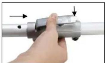
natural_image
Close-up of a hand holding a metallic cylindrical tool with arrows pointing to the handle (no text or symbols visible)
natural_image
Hand holding a metallic tool with a handle, against a plain white background (no text or symbols visible)8. Montage Motorsense / Rasentrimmer
natural_image
Close-up of a black and orange robotic brush tool with a lever handle (no text or symbols visible)Montage des Metalblatts (Motorsense)
Schritte:
text_image
Exploded view diagram of a mechanical component with numbered parts labeled 2, 3, and 4
natural_image
Two-step diagram showing a mechanical tool being inserted into a motor, with no visible text or symbols.text_image
2 1 Warning!natural_image
Line drawing of a person walking with a utility pole, no text or symbols presenttext_image
Labeled diagram of a mechanical tool with numbered parts, showing a hatched blade assembly and orange base strips.Erläuterung
- Schneideklingen
natural_image
Line drawing of a person using a manual shoveling soil or vegetation, no text or symbols presenttext_image
Technical diagram showing hands operating a mechanical tool with labeled parts (1)natural_image
Line drawing of a person walking with a long tool, no text or symbols presenttext_image
Technical diagram of a chain saw with numbered parts, showing mechanical components and assembly details.Erläuterung
natural_image
Line drawing of a person using a power tool in an outdoor setting (no text or symbols)natural_image
Illustration of a person holding a long tool, wearing a helmet and gloves (no text or symbols)natural_image
Technical line drawing of a mechanical component with no visible text or symbols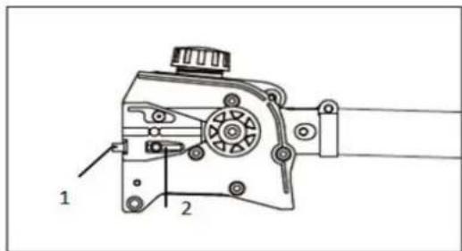
text_image
Technical diagram of a mechanical device with labeled parts 1 and 2natural_image
Illustration of a hand using a chain to cut a single tree branch (no text or symbols)
text_image
1 4natural_image
Diagram of a mechanical device emitting smoke or vapor onto a conveyor belt (no text or symbols present)natural_image
Line drawing of a hand pressing down on a mechanical component with a magnified view (no text or symbols)natural_image
Technical line drawing of a mechanical device with no visible text or symbolsnatural_image
Diagram of a chain-linking device emitting arrows, showing motion direction (no text or symbols)natural_image
Diagram of a diagonal saw cutting a circular object, no text or symbols presenttext_image
Technical diagram showing a mechanical linkage system with labeled components 1 and 2, including a shaded circular component.natural_image
Diagram of a mechanical or fluid system with a curved pipe and circular component, no visible text or symbolsnatural_image
Diagram showing a curved object with arrows indicating motion or flow, no text or symbols presentRückzug vermeiden
natural_image
Diagram showing a curved path with directional arrows and a circular element, labeled 'B' (no text or symbols beyond label)Rückstoß vermeiden
text_image
Technical diagram of a mechanical device with numbered parts labeled 1, 2, and 3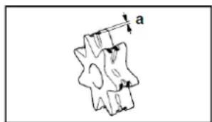
text_image
anatural_image
Technical line drawing of a mechanical assembly with no visible text or symbolsnatural_image
Technical line drawing of a mechanical tool or tool with no visible text or symbolsnatural_image
Pure mechanical component diagram without any text, numbers, or symbolsnatural_image
Mechanical assembly diagram showing a lever mechanism interacting with a cylindrical component (no text or symbols visible)
natural_image
Close-up of a hand holding a metallic mechanical component with arrows indicating direction (no text or symbols visible)
natural_image
Hand holding a metal tool with a handle, against a plain white background (no text or symbols visible)natural_image
Mechanical assembly diagram showing a lever mechanism with a handle and pivot point (no text or symbols)natural_image
Close-up of a hand holding a metallic mechanical component with arrows indicating direction (no text or symbols visible)natural_image
Hand holding a metallic tool with a handle, against a plain white background (no text or symbols visible)natural_image
Close-up of a FUXTEC tool with a metallic handle and black base, labeled '1.' (no text or symbols on the tool itself)
natural_image
Close-up of a Fuxtec chain saw with orange jaw and black handle, showing blade and tool movement arrows (no text or symbols on the saw itself)natural_image
Mechanical component with red arrow indicating direction, no visible text or symbols
natural_image
Close-up of a mechanical component with orange tool and red arrow indicating upward motion (no text or symbols)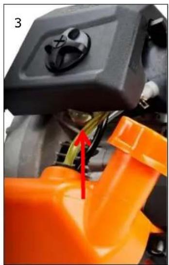
natural_image
Close-up of a mechanical component with orange and black parts, no visible text or symbolsnatural_image
Close-up of a black 3D printer with orange base and orange handle, showing mechanical components and a red arrow indicating a tool (no text or symbols visible)
natural_image
Close-up of a hand adjusting a black industrial machine component with orange clamps (no visible text or symbols)natural_image
Technical line drawing of a mechanical device with a downward arrow indicator (no text or symbols)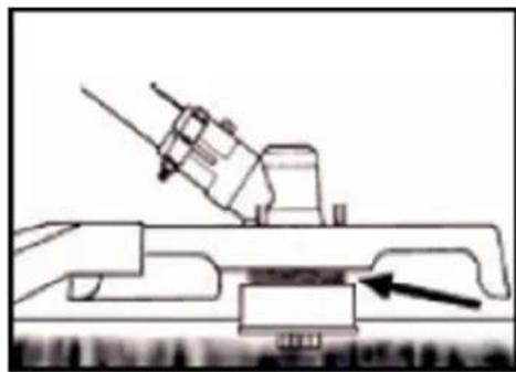
natural_image
Technical line drawing of a mechanical assembly with an arrow indicating a component (no text or symbols present)natural_image
Diagram of a mechanical device emitting particles with motion arrows indicating flow (no text or symbols)TRIMMEN UM BÄUME
natural_image
Close-up of hands holding a small mechanical component with a wire, no visible text or symbols
natural_image
Close-up of hands holding a black mechanical component (no visible text or symbols)natural_image
Close-up of a hand holding a black mechanical component against a cloudy sky (no visible text or symbols)
natural_image
Close-up of hands holding a black cylindrical object with a circular base (no visible text or symbols)natural_image
Technical line drawing of a mechanical assembly with no visible text or symbols17. Wartungsplan
natural_image
Close-up of a hand adjusting a black 3D printer with orange handle (no visible text or symbols)
natural_image
Close-up of a mechanical device with orange and black components, showing internal structure and housing (no text or symbols visible)Wartung Zündkerze
text_image
0.6~0.7mmWARNUNG

natural_image
Close-up of a mechanical component with labeled parts F and E, showing internal components and a ruler-like structure (no readable text or symbols beyond labels)Warnung!
Multifunctional petrol cutter
FX-MT152/-MT152E/-MT252E

natural_image
Product photo of multiple manual tools including a shovet, saw, and power tools (no text or symbols visible)CE
Your new device has been developed and designed to meet FUXTEC's high standards, such as easy operation and user safety. Properly treated, this device will serve you well for years to come.

WARNING: To reduce the risk of injury, the user must read and understand this manual before operating the device.
FUXTEC GmbH
KAPPSTRAße 69, 71083 HERRENBERG-GÜLTSTEIN, GERMANY
TABLE OF CONTENTS
-
TECHNICAL DATA....59
-
SYMBOLS AND SAFETY INSTRUCTIONS ON THE DEVICE AND ATTACHMENTS61
-
INTENDED USE AND GENERAL SAFETY INSTRUCTIONS....65
-
NOTES ON ACCESSORIES....69
-
ATTACHING THE SHOULDER STRAP ....70
-
COMPONENT OVERVIEW....71
-
MOUNTING THE ALL-ROUND HANDLE/ATTACHMENTS....72
-
MOUNTING THE MOTOR SCYTHE/GRASS TRIMMER....73
-
USING THE HEDGE TRIMMER ATTACHMENT....76
-
USING THE BRANCH SAW ATTACHMENT....79
-
USING THE 1M EXTENSION FOR MT152E....91
-
USING THE PIVOTING BRANCH SAW ATTACHMENT ON THE MT252....92
-
STARTING/STOPPING THE DEVICE 93
-
REFUELING THE ENGINE....94
-
TRIMMING TECHNIQUES....96
-
REPLACING NYLON THREAD....98
-
MAINTENANCE PLAN....99
-
STORAGE OF THE DEVICE....101
-
TROUBLESHOOTING....102
-
INFO: OPTIONAL ACCESSORIES (ADJUSTABLE POLE SAW)....103
- CUSTOMER SERVICE....104
- WARRANTY....104
- DISPOSAL NOTE....104
We are continually striving to improve our products. Therefore technical data and illustrations may change!
25. Technical Data
| Type | FX-MT152/-MT152E/-MT252 |
| Engine | air-cooled; 2-stroke |
| Cubic capacity | 52cm^3 |
| Maximum output power (kW)(in accordance with ISO 8893) | 2.2kW / 7,500min^-1 |
| The maximum speed of the engine | 9,000 min^-1 |
| Idle speed of the engine | 3,000 min^-1 |
| The maximum speed of the spindle(motor scythe) | 7,100 min^-1 |
| The maximum speed of the spindle(grass trimmer) | 6,600 min^-1 |
| LPA at the operator's position | 99.5dB(A) (K=3dB) |
| Measured LWA according to ISO 10884 | 107.7dB(A) (K=3dB) |
| Guaranteed LWA | 111dB(A) |
| Maximum vibration values at each handle | 9.661m/s^2 k=1.5m/s^2 |
| Maximum diameter of the threads | Φ2.5mm |
| Diameter of the metal blade | 305mmx1.6mm-2T / 255mmx1.6mm-3T/255mmx1.6mm-4T/ 255mmx1.6mm-8T |
| Rotation direction of the cutting device | counterclockwise (see the mark on the plate) |
| Number of the handle | 1 piece |
| Dry weight (without fuel, cutting assembly, carrying strap) | 7.2kg |
| Fuel tank capacity (L) | 1.2 |
| Fuel consumption (kg/h) (in accordance with ISO 8893) | 0.89 kg |
| Specific fuel consumption (g/kWh)(in accordance with ISO 8893) | 630 g |
| Hedge trimmer attachment Blade length | 390mm |
| Hedge trimmer attachment Working angle | 270^ - 90^ |
| Hedge trimmer attachment max.thickness | 19mm |
| High feeler attachment Sword | 12'' (300mm) / AL12-44-507P |
Original Bedienungsanleitung FUXTEC FX-MT152/-MT152E/-MT252_de_en_fr_ita_es_rev20
| length/ type | |
| Saw chain/chain pitch | TT-9D-3B / Pitch 3/8" |
| Pole saw max. cutting length | 290mm |
| Oil tank capacity Chain lubrication | 150ml |
26. Symbols and safety instructions on the device and attachments
| Warnings on the primary device Multifunction Cutter | |
 | WARNING! IMPROPER OPERATION MAYLEAD TO SERIOUS INJURY |
 | READ AND UNDERSTAND THIS USER MANUAL BEFORE USE. |
 | ALWAYS WEAR EYE PROTECTION, EAR PROTECTION, AND MOUTH PROTECTION. |
 | WEAR FOOT PROTECTION. |
 | WEAR GLOVES. |
 | DO NOT TOUCH THE ROTATING BLADE,DANGER OF INJURY! |
 | WARNING AGAINST FLYING OBJECTS! |
 | WARNING! FLAMMABLE MATERIALS! |
 | ALWAYS KEEP 15 METERS AWAY FROM DISTANCE! |
 | MAXIMUM NUMBER OF ROTATION OF THE SPINDLE (GRASS TRIMMER): 6600 min ^-1 |
 | MAXIMUM ROTATION SPEED OF THE BLADE (MOTOR SCYTHE):7100 min ^-1 |
 | THE GUARANTEED NOISE LEVEL COMPLIES WITH THE LEGAL NOISE GUIDELINES. |
 | DO NOT SMOKE AND AVOID NAKED FLAMES ON THE DEVICE. |
 | WARNING: DANGER OF HOT COMPONENTS! |
| Additional warnings for the hedge trimmer attachment: | |
 | MOUNT THE DRIVE SHAFT CAREFULLY ONTO THE GEARBOX. |
 | ALWAYS WEAR EYE PROTECTION! |
 | ALWAYS WEAR HEARING PROTECTION! |
Additional warnings for the hedge trimmer attachment:
| Additional warnings for the pole saw attachment | |
 | ALWAYS WEAR EYE PROTECTION, EAR PROTECTION, AND HEAD PROTECTION! |
 | ALWAYS WEAR PROTECTIVE CLOTHING! |
 | ALWAYS KEEP A MINIMUM DISTANCE OF 10M BETWEEN THE DEVICE AND HIGH VOLTAGE LINES! |
 | ALWAYS TURN THE DEVICE OFF AND MAKE SURE THE CUTTING TOOL IS STOPPED BEFORE CLEANING, REMOVING OR ADJUSTING IT. |
 | WARNING:EXHAUST GASES OF THIS PRODUCT CONTAIN CHEMICALS THAT CAUSE CANCER, BIRTH DEFECTS AND MAY CAUSE FURTHER DAMAGE |
 | WARNING! NEVER CHANGE THE MACHINE. IMPROPER USE OF THE DEVICE CAN CAUSE SERIOUS OR FATAL PERSONAL INJURY. |
Do not allow others to use this device unless they have been fully instructed, have read and understood the device manual, and have been trained in the operation of the device.

Prolonged use of the device exposes the user to shocks that can lead to white finger disease (Raynaud's syndrome) or carpal tunnel syndrome. This condition reduces the hand's ability to sense and regulate temperature,
causes numbness and heat sensations, and can lead to nerve and circulatory damage and tissue death.
Not all factors leading to white finger disease are known. Still, cold weather, smoking, and other conditions affecting the blood vessels and blood circulation, as well as extensive or prolonged exposure to shocks, are mentioned as factors in the development of white finger disease. To reduce the risk of white finger disease and carpal tunnel syndrome, please note the following
- Wear gloves and keep your hands warm.
• Take regular breaks.
All the above precautions cannot eliminate the risk of white finger disease or carpal tunnel syndrome. Long-term and regular users are, therefore, advised to closely monitor the condition of their hands and fingers. Consult a doctor immediately if any of the above symptoms occur.

The operating noise of the tool may damage your hearing. Wear a sound-proofing (Oropax or ear muffs) to protect it. Long-term and regular users are recommended to check your hearing regularly. Be especially vigilant and careful when wearing hearing protection as it limits your ability to hear warnings (cries, alarms, etc.).

WARNING: Some noise exposure from this device is unavoidable. Do not work in environments during approved and designated times. If necessary, observe rest s and limit the duration of work to the minimum required. For your personal tion and the protection of persons in the vicinity, wear suitable hearing protection.
27. Intended use and general safety instructions
This device may only be used with the scythe attachment for mowing or trimming grass, weeds, and undergrowth. The hedge trimmer attachment is to be used exclusively for trimming hedges, the branch saw attachment is to be used solely for delimbing and trimming tree crowns.
Never use it for other purposes, as this can cause serious injuries!
Correct safety instructions must be followed. DO NOT EXPOSE YOURSELF OR OTHERS TO DANGER. Follow these general safety instructions:
- Always wear safety glasses for your eyes. Long hair must be tied back. Do not wear loose clothing or jewelry that could get caught in moving parts of the device. Safe, secure, non-slip safety shoes must always be worn. It is recommended that legs and feet are fully protected to guard against flying objects during operation.
- Check the entire device for loose parts (nuts, bolts, screws, etc.). Service or replace them if necessary before using the device. Do not use accessories with this drive head other than those recommended by the manufacturer. Otherwise, severe injury to the user or bystanders and damage to the device may result.
- Keep the handles free of oil and fuel.
- Always use correct handles and the shoulder strap when cutting.
- Do not smoke when mixing fuel or filling the tank.
- Do not mix fuel in a closed room or near open fires. Ensure sufficient ventilation/air circulation.
- Mix and store the fuel mixture in a sealed container approved for such use according to local regulations.
- Never remove the fuel tank cap while the device is running.
- Do not operate the device in closed rooms or buildings. Exhaust gases contain dangerous carbon monoxide.
- Do not attempt to adjust the device while running or carrying it. Always fix the device on a flat, free surface
- Do not use the device if it is damaged. Never remove any protective devices from itself. Otherwise, the operator or persons may be seriously injured, and further damage to the device may result.
- Check the area to be cut and remove any objects that may be entangled in the nylon cutting head or cutting blade. Also, remove all possible objects that the device could throw around during cutting.
- Never leave the device unattended.
- Do not stretch out far forward. Always maintain a firm stand and balance. Never let the device run while standing on a ladder or any other unstable standing position.
- Children must not have access to the device. Spectators should stand at a safe distance from the working area, at least 15 meters.
- Keep hands and feet away from the nylon cutting head or metal blade during operation.
- Do not use the device if you are tired, ill, or under the influence of medication, drugs, or alcohol.
- Use an undamaged nylon cutting head. If you hit a stone or any other obstacle, stop the device and check the nylon cutting head. Never use a defective or unbalanced nylon cutting head.
- Before starting, after failure or impact, always check the device and make sure it is in good condition.
- Attention! Local regulations may limit the use of the device.
- Always keep the device with the cutting tool in good condition. Note, improper maintenance, the use of non-compliant spare parts or removal, or modification of safety devices can cause damage to the device, and severe injury to the person working with it.
- Secure the device well during transport to prevent fuel loss, damage to the device, and injury. Always fit the transport protection of the cutting blade before transporting or stowing the device.
- On devices with a clutch, regularly check that the cutting attachment stops rotating when the engine is idling.
- Always check the device for loose fasteners, fuel leaks, damaged parts, etc. before each use. Replace used parts before further use.
- Do not store the device in an enclosed area where fuel vapors can reach an open fire from water heaters, stoves, etc. Store the device only in a well-ventilated area.
- IMPORTANT: When filling the fuel, make sure that the device is off and cooled down. Never refuel when the device is running or hot. If gasoline is spilled, wipe up before starting the engine.
Safety Instructions for Hedge Trimmer
- THESE HEDGE TRIMMERS CAN CAUSE SERIOUS INJURIES! Carefully read the instructions for correct handling, preparation, maintenance, starting, and stopping of the hedge trimmer. Familiarize yourself with all controls and proper use of the hedge trimmer.
- Children must never use the hedge trimmer.
- Beware of overhead power lines.
- Avoid using the hedge trimmer when people, especially children, are near it.
- Wear suitable clothing! Do not wear loose clothing or jewelry that can be caught by moving parts. It is recommended to wear sturdy gloves, non-slip shoes, and safety goggles.
- Handle fuel with care, it is highly flammable, and the vapors are explosive. The following points should be followed.
- Use only specially designed containers.
- Never remove the filler cap or add gasoline while the engine is running or hot. Allow the engine and exhaust parts to cool down before refilling.
- Do not smoke.
○ Only refuel outdoors. - Never store the hedge trimmer or fuel tank in a room with an open flame, such as a water heater.
- If gasoline has leaked, do not attempt to start the engine, but remove the gasoline residue from the device before starting.
- Always replace the fuel cap after filling the tank and close it securely.
- If the tank is emptied, this should be done outdoors.
- If the cutting device touches a foreign object or if the operating noise increases or the hedge trimmer vibrates unusually strongly, stop the engine and let the hedge trimmer come to a standstill. Remove the spark plug connector from the spark plug and take the following actions:
- check for damage;
- check for loose parts and secure all loose parts;
- replace damaged parts with equivalent parts or have them repaired.
- Warning! Always wear hearing and eye protection when using the device.
- Instructions on how to stop the hedge trimmer in an emergency: Unlock the throttle. Let the device return to idle. Push the engine stop switch on the handle upwards until the device stops. If it does not stop, pull out the spark plug connector in an emergency. Never leave the device unattended while it is running.
Notes for operation
a) The engine must be stopped before:
cleaning or removing a blockage;
inspection, maintenance or work on the hedge trimmer;
adjusting the working position of the cutting device;
leaving the hedge trimmer unattended.
b) Always ensure that the hedge trimmer is appropriately in one of the specified working positions before starting the engine.
c) Always ensure that the hedge trimmer is in a safe position when operating the hedge trimmer. Do not step on the hedge trimmer or use a ladder.
d) Do not use the hedge trimmer with a defective or heavily worn cutting device.
e) To reduce the risk of fire, ensure that the engine and silencer are free of deposits, leaves, or escaping lubricant.
f) Always ensure that all handles and safety devices are fitted when using the hedge trimmer. Never attempt to use an incomplete hedge trimmer or one with an unauthorized modification.
g) Always use both hands when using the hedge trimmer attachment.
h) Always familiarize yourself with your surroundings and be aware of potential hazards that you may not be able to hear because of the noise of the hedge trimmer.
Maintenance and Storage Instructions
d) When the Multitool is stopped for maintenance, inspection, or storage, turn off the engine, remove the spark plug connector from the spark plug and make sure all rotating parts have stopped. Allow the device to cool down before checking, adjusting, etc.
e) Store the device where petrol vapors cannot come into contact with naked flames or sparks. Always allow the hedge trimmer to cool down before storing it.
f) When transporting or storing the device, always cover the cutting device with the cutter guard.
28. Notes on accessories
- Make sure that your product is only equipped with original accessories. Only use original parts that are specified by the manufacturer. The use of any other attachments or accessories may cause injury to the user and damage to the device.
- Clean the device thoroughly, especially the fuel tank and air filter. After using the device, remove all fuel.
- If you approach a user of the device as a spectator, carefully attract his attention and confirm that the user will stop the device. Please do not startle or distract the user. Otherwise, you could cause an unsafe situation.
- Never touch the nylon cutting head or metal blade when the device is running. If it is necessary to replace the guard or cutting tool, be sure that the device and cutting tools have stopped.
- The device must be OFF before you change the working range.
- When starting or operating the device, never touch hot parts such as the exhaust, ignition cables, or spark plug.
- After the device has stopped, the exhaust pipe is still hot. Never place the device near inflammable materials (dry grass, flammable gases or liquids, etc.).
- Pay particular attention to the fact that the ground may be slippery when operating the device in the rain or immediately after the rain.
- If you slip or fall to the ground, release the throttle immediately.
- Be careful not to drop the device or hit it against obstacles.
- Before adjusting or repairing the device, make sure that the device is stopped, and the spark plug connector is removed.
- Before removing blockages, stop the device and remove the spark plug connector.
- If the device is to be stored for an extended period, drain the fuel from the fuel tank and carburetor, clean the parts, place the device in a safe place and ensure that the device has cooled down completely.
- Perform constant checks to ensure the safe and efficient operation of the device.
- Keep the device away from fire or sparks.
- Be careful when using the device. There is a risk of kickback and recoil.
- Use extreme caution when using this device with the cutting blade. A cutting blade kickback is a reaction that can occur when the rotating cutting blade hits an object that cannot be cut. This contact causes the cutting blade to stop for a moment and then suddenly repels from the hit object with accelerated force. This kick-back reaction can be severe enough that the operator loses control of the device. A cutter blade kickback can occur without warning if the cutter blade encounters an obstacle, becomes blocked or jams. This is more likely in areas where it is difficult to see the material being cut. For easy and safe cutting, approach the weeds to be cut from your right to your left side. If an object or stick of wood is hit unexpectedly, this can reduce a cutter
blade kickback.
29. Attaching the shoulder strap
Adjusting the carrying strap
Shoulder Strap
- Put your shoulder strap over one shoulder
- Adjust the strap length (with the attachment attached) so that the spring hook is at the height of your right hip

natural_image
Person wearing a white shirt and black pants holding a long-handled tool, standing against a plain white background (no text or symbols visible)Attention
Never wear the belt diagonally over the shoulder and chest, but only on one shoulder, so that you can quickly remove the device from your body in case of danger.
30. Component overview

text_image
Labeled diagram of a manual tool set with numbered parts for identification- Exhaust pipe
- Pullstarter
- Gas cap
- Air filter
- Spark plug
- Throttle
- Throttle lock*
- Start/stop switch
- All-round handle
- Connector
- Branch saw attachment
- Chainguard
- 3-tooth metal knife
- Shield
- Cutting blades
- Nylon thread head
- Hedge trimmer attachment
- Knife protection
- Shoulder strap
- 1m extension
- Pivoting branch saw attachment
*7 Throttle lock prevents accidental acceleration of the engine. The throttle stick can only be pressed when the throttle stick lock is pressed.

natural_image
Close-up of a black mechanical device with orange handle and black strap, labeled 'PATEL 19' (no other text or symbols visible)Only for MT152E:
Only for MT252:
20
natural_image
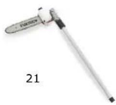
Close-up of a laboratory pipette with a metallic handle and label '21' (no text or symbols on the device itself)31. Mounting the all-round handle/attachments
Attaching the handle
The handle must be fitted before use.
Follow the illustrations below for correct installation.
Mounting the wrap-around handle
• There are four holes for mounting the wrap-around handle
• Take the wrap-around handle.
- Align the position of the holes.
- Insert the screws into the holes and tighten them until you feel resistance.
- Tighten the screws well.

natural_image
Black mechanical device with handle and lever, labeled 'Gummimuffel + 4 Imbussschrauben M5x35' (no other text or symbols visible)
natural_image
Close-up of a black and black mechanical tool with a handle and lever mechanism (no text or symbols visible)Mounting the attachments
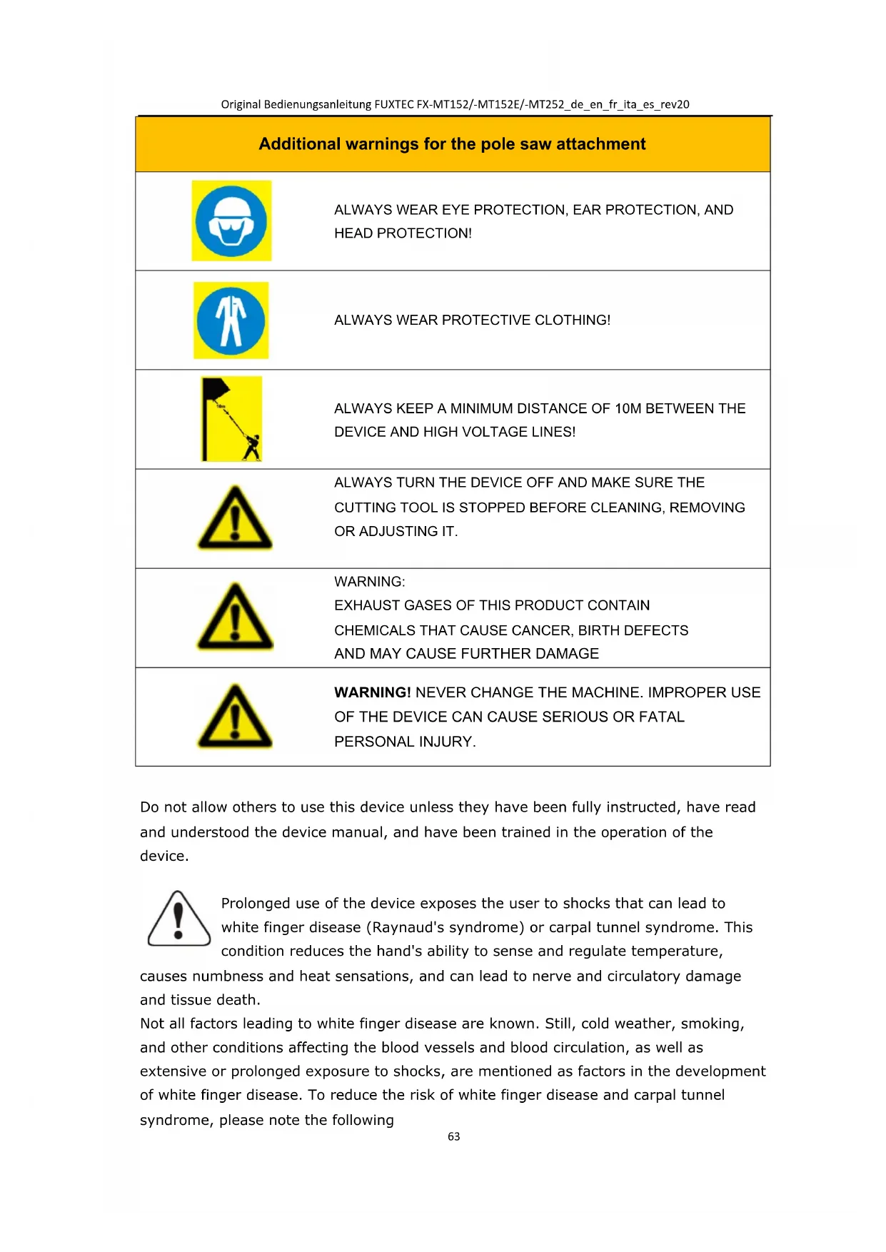
1). Place the drive axle against the main shaft so that the hole of the axle is aligned with the locking pin of the connecting piece.
2). Actuate the locking pin and insert the drive axle into the main shaft. Release the locking pin and ensure that the locking pin engages in the hole.
3). Turn the wing screw clockwise to secure the connection.

natural_image
Mechanical assembly diagram showing a lever mechanism with a handle and pivot point (no text or symbols)
natural_image
Close-up of a hand holding a metallic cylindrical tool with arrows indicating movement or force (no text or symbols visible)
natural_image
Hand holding a metallic tool with a handle, against a plain white background (no text or symbols visible)32. Mounting the motor scythe/grass trimmer
A metal blade with 3 teeth is delivered with the device. It is used for cutting bushes and weeds. The use of the saw blade with this device is prohibited.
WARNING

Do not cut with blunt, cracked or damaged metal sheets.
Before working, check the surface for obstacles such as stones, metal bars or other objects. If they cannot be removed,
mark this position to avoid collision with
the blade. Lines can become entangled on the blade head and flap or be swirled in the air.
WARNING

Always use the shoulder strap. Adjust and fix the belt and
belt clamping plate on the device so that the device hangs a few cm above the ground. The cut-out head and the protective shield should be aligned horizontally in all directions. Pre-tension the machines on the right side of your body.
WARNING

Do not use the brushcutter for cutting out trees.
WARNING

Also, wear head, eye, face and hearing protection, and safety shoes. Do not wear rings and jewelry or
loose, dangling clothes that could get caught in the device.
Do not wear footwear with unprotected toes and do not work barefoot or without leg protection. In certain situations, you must wear head protection.
Installation of the protective shield
Install the protective shield on the driveshaft tube against the gearbox housing. Tighten the holder of the guard so that the blade guard does not move or slide down during operation.
Mounting the metal blade (motor scythe)
Steps:
- Place the key (1) in the hole on the gearhead.
- Remove the nut, the cover (4) and the upper spacer disc (3) from the gear shaft
- Place the metal sheet on the lower Distance washer (2). Make sure that the marked side of the cutting blade is in contact with the disc (2).
- Slide the upper spacer disc (3) over the Gear shaft onto the metal sheet. Pay attention to this, the upper side of the cutting blade makes contact with the spacer disc (3).
- Place the cover (4) in place and screw the Union nut tight with locked gear head (see point 1)

natural_image
Close-up of a black and orange robotic brush tool with a lever handle (no text or symbols visible)
natural_image
Close-up of a black industrial fan or support structure with a metallic wheel and metal bracket (no text or symbols visible)
text_image
2

©

natural_image
Two-step diagram showing a tool being inserted into a mechanical component, with no visible text or symbols.Mounting the grass trimmer
Step one:
Insert the key (1) into the hole in the gearhead so that the gear shaft is locked. Unscrew and remove the nut. As this is a safety nut, please make sure that there is a left-hand thread
Step two:
mount the cover (2), install the yarn package on the gear shaft. And then tighten it by hand.

text_image
2 Warning! 1Warning!
Ensure that all components are correctly assembled and installed and that all screws are tightened.
33. Using the hedge trimmer attachment
Transport of the hedge trimmer
Warning!
Never carry or transport your device with the blades running to avoid the risk of injury.
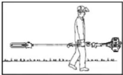
Always carry it in a horizontal position only. Grip the bar so that the device is horizontally balanced. Keep the hot muffler away from your body and the cutting attachment behind you.

natural_image
Line drawing of a person walking with a utility pole, no text or symbols presentAlways switch off the engine and place the blade guard over
the blades before transporting the tool over long distances. When transporting the tool in a vehicle, secure it appropriately to prevent it from tipping over, leaking fuel, and damaging the device.
For devices with adjustable bar: Make sure it is in a secure position.
Warning!
Never operate your tool with only one hand. The resulting loss of control can lead to severe or fatal injuries. Keep hands and feet away from the cutting tool to avoid the risk of injury. Never touch a running cutting tool with any part of your body.
Warning!
Do not bend forward too far. Always maintain your balance and a secure footing. Special care is required when there is a danger of slipping (wet ground, snow) and challenging, overgrown terrain. Watch out for hidden obstacles such as tree stumps, roots, and puddles to avoid tripping. Remove fallen branches, undergrowth, and cuttings. Be extremely careful when working on sloping or uneven ground. Never work on a ladder, tree branch, or another unsafe surface. Never lift the tool above shoulder height.
Warning!
The tool blades continue to run for a short time after the throttle lever is released (flywheel effect). The acceleration of the engine while the blades are blocked causes the clutch to slip further. This can lead to overheating and damage to essential components (including clutch, polymer housing component). This, in turn, can lead to a risk of injury due to running blades despite idling adjustment.
For devices with adjustable bar: Carefully place the bar in the desired working position. Do not touch the blades to avoid injury. Only make adjustments when the blades are
stationary.
1 Cutting blades
2 Blade protection
3 Blade gear
4 Lockout
5 Angle drive
6 Setting lever
7 Drive axle tube
Explanation
- Cutting blades
Steel blades for cutting hedges and undergrowth
- Blade protection
Protects the cutting bar when the tool is not in use
- Blade gear
Converts the rotation of the angular drive into the reciprocating movements of the cutting blades
- Block
Holds the cutting bar in the desired position
- Angle drive
Transfers the rotary motion of the drive axle to the blade drive
- Setting lever
Adjusts the cutting bar to the desired angle
- Drive axle tube (tree)
Surrounds and protects the drive axle between the coupling sleeve and the gearbox.
General
Besides the intended use for cutting hedges at height, the hedge trimmer can also be used on the ground. Because its blades work like a mower, it is ideal for cutting undergrowth, thicket, reeds, wild growth, and more durable grass. The hedge trimmer is particularly suitable for busy places such as traffic islands or parks, as the cuttings are not thrown around by the blades.

natural_image
Line drawing of a person using a manual lawn brush on a grassy path (no text or symbols)Preparation
Always wear the carrying strap.
Do not throw the clippings in the waste bin. It can be composted.
Cutting technique
The working posture and method are exactly the same as for the motor scythe. The cutting bar is moved back and forth, just above the ground.
Adjusting the cutting angle of the hedge trimmer attachment

text_image
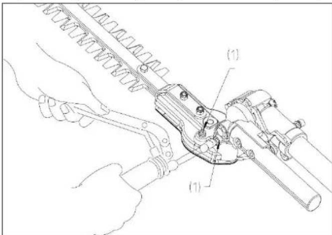
1 2 3Adjust the cutting angle: Release the lock (1), simultaneously pull the two release levers (2) and turn the blade position to the desired angle via the adjusting lever (3). Make sure that the lock (1) is always engaged.
Maintenance of the attachment:
Top up 20 grams of grease/lubricant every 25 operating hours.
text_image
Technical diagram of a mechanical tool with labeled parts (1) and (2), showing hands operating a tool assembly.Use a grease gun to press the lubricant into the nipples (1).
34. Using the branch saw attachment
Transport of the tool
Warning!
Always carry it in a horizontal position only. Grip the bar so that the device is horizontally balanced. Keep the hot muffler away from your body and the cutting attachment behind you. Unintentional acceleration of the engine can cause the saw-chain to rotate and cause serious injury.
natural_image
Line drawing of a person walking with a long tool, no text or symbols presentAlways switch off the engine and slide the rail guard over the cutting attachment before transporting the tool over long distances. When transporting the tool in a vehicle, secure it appropriately to prevent it from tipping over, leaking fuel, and damaging the device.
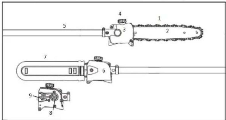
Main components and control elements
1 = Saw chain
2 = Guide rail
3 = Oil tank
4 = Oil tank cover
5 = Drive axle
6 = Sprocket cover
7 = Chain guard
8 = Sprocket wheel
9 = Chain tensioner
text_image
5 4 1 3 2 b 7 6 9 8Explanation
- Saw chain: A chain of knives, straps and dynamic links
- Guide rail: Holds and guides the saw chain
- Oil tank: Oil tank to lubricate the chain
- Oil tank cap: Seals the oil tank
- Drive axle: Connecting element between the engine and gearbox
- Sprocket cover: Covers the sprocket
- Chainguard (protective cover): Protects the chain while the device is out of service and during transport and storage.
- Sprocket: Gearwheel that moves the saw-chain
- Chain tensioner: Ensures the chain tension is precisely adjustable
Before starting
Remove the guard from the chain and inspect the chainsaw for proper operating conditions (see maintenance and sharpening of the saw-chain on page 33).
Before starting your engine, always check that it is in good condition, especially the throttle, the throttle lock, the stop button, and the tool attachment. The throttle stick must be free to move and always return to the idle position. Never attempt to modify the control or safety devices.
Never use a damaged, poorly adjusted or serviced or incompletely and securely mounted device.
Always keep the handles clean and dry. It is especially important to protect them from moisture, soot, oils, grease, or resins to ensure safe handling and control of your device.
The correct chain tension is fundamental. The tensioning procedure in this manual on page 28f. must be followed to avoid improper tension. Make sure that the hexagonal bolts for the sprocket cover are then tightened firmly. Recheck the chain tension after tightening the bolts.
Never start work with an unattached sprocket cover. Adjust the carrying strap and handle it to your size before beginning work.
Place the saw on firm ground or another firm surface outside, or as shown in the picture. Maintain a secure footing and balance.

natural_image
Line drawing of a person tending to a tree with a long-handled stick (no text or symbols)Make sure there is nothing near the guide bar and the saw chain to reduce the risk of injury.
Attach the tool to the hooks on your harness when the engine is idling (see relevant section).
Important notes
The correct chain tension is always significant. Check it regularly (every time the chainsaw is switched off). If the chain becomes loose during cutting, turn off the engine to tighten it. Never do this while the engine is running.
During operation
Holding and controlling the tool

natural_image
Illustration of a person holding a long tool, wearing a helmet and gloves (no text or symbols)Always hold the device by the handles with both hands during operation. Close your fingers and thumbs around the handles.
Place your left hand on the front handle and your right hand on the rear handle on the throttle. This also applies to left-handed users.
Always keep your hands in this position to keep your saw under control.
Never try to operate your tool with one hand. Losing control of your
device can cause severe or fatal injury.
Always keep your balance and a secure footing to maintain control of your chainsaw. Never work on a ladder, tree branch, or another unsafe surface. Never lift the device above shoulder height. Do not bend forward too far. Use a lifting platform to work at the height of more than 4.5 meters.
Special care is required when working on slippery surfaces (wet ground, snow) and on steep, overgrown terrain. Watch out for hidden obstacles such as tree stumps, roots, and puddles to avoid tripping. Remove fallen branches, undergrowth, and cuttings. Be extremely careful when working on sloping or uneven ground.
Be extremely careful in wet and frosty conditions (rain, snow, ice). Interrupt work in the event of wind, storm, or heavy rain.
Operating instructions
Warning!
Keep hands and feet away from the cutting tool to avoid the risk of injury. Never touch a running cutting tool with any part of your body.
The saw-chain continues to run for a short time after you release the throttle stick (inertia).
The acceleration of the engine while the blades are blocked causes the clutch to slip.
This can lead to overheating and damage to essential components (including clutch, polymer housing component). This, in turn, can lead to a risk of injury due to running blades despite idling adjustment.
If the chain is stuck, always switch off the engine before cleaning and make sure that the chain is stationary.
Make sure that the saw-chain does not come into contact with foreign objects such as
stones, fences, nails, etc. These objects could be thrown away and injure the user or bystanders or damage the saw chain.
Before cutting, clear the work area of unwanted branches and undergrowth. Then create a retreat area, away from the place where cut branches may fall, and remove all obstacles there. Keep the work area clear, remove the cut branches immediately. Place all other tools and devices at a safe distance from the branches to be cut, but not in the retraction area.
Always observe the condition of the tree. Look for rot and decay in the roots and branches. If they are rotten on the inside, they may unexpectedly break off and fall off during pruning. Also, look for broken and dead branches that could be loosened by the shock and fall down on you. If the branches are very thick or heavy, first make a small incision under the branch before working from top to bottom to prevent breakage.
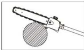
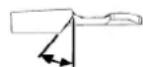
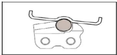
To reduce severe or fatal injuries from falling objects, never cut vertically above your body. Hold the chain saw at an angle of no more than 60^ from the horizontal (see illustration). Objects may fall in unexpected directions. Never stand directly under the branch you are cutting.
Watch out for falling branches! Immediately stepaside and keep a sufficient distance from the fallingwood as soon as a cut branch begins to break off.

text_image
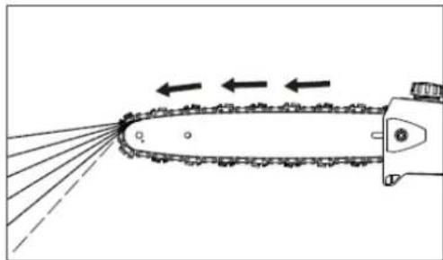
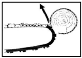
max 60°Always pull the device out of the cutting gap while the chain is running to prevent the saw from jamming. Do not exert pressure when you reach the end of a sawing operation. This can cause the guide bar and the running saw chain to jump out of the cutting gap uncontrollably, which in turn can hit other objects.
If the guide bar is jammed in a branch so that the chain cannot move any further, switch off the saw and carefully move the branch to open the gap and release the bar.
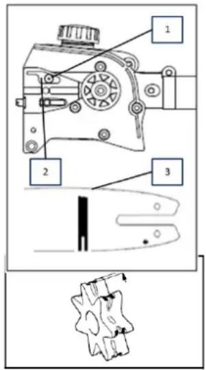
Mounting the guide bar and saw chain
Warning! Adjust the guide bar and chain only when the engine is not running.
natural_image
Technical line drawing of a mechanical component with no visible text or symbols
text_image
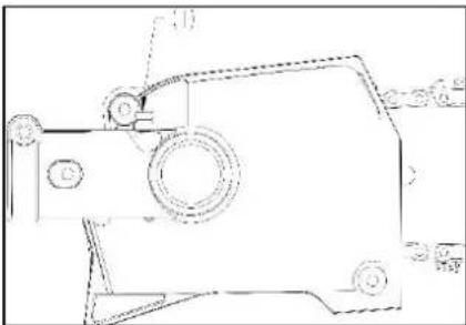
Technical diagram of a mechanical device with labeled parts 1 and 21 Loosen the nut and remove the sprocket cover.
2 Turn the tensioning screw (1) clockwise until the tensioning nut (2) stops at the left. The chain is very sharp. Wear work gloves to avoid cutting yourself.
natural_image
Illustration of a hand using a chain to cut a single tree branch (no text or symbols)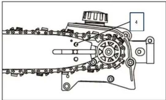
text_image
Technical diagram of a mechanical device with labeled parts and components4 Place the chain on the guide bar, starting at the bar/sword tip.
4 Insert the guide bar into the attachment bolt. Insert the pin on the tensioner into the hole (4) and place the chain on the sprocket at the same time.
5 Replace the sprocket cover and tighten the nut by hand.
6 Now turn the tensioning screw (1) clockwise until the chain hangs only minimally on the underside of the rail, and the tang of the chain links is in the running groove of the rail.
Tensioning the saw chain
Restore tension during the cutting operation:
- Switch off the engine and loosen the nut a little.
- Hold the rail tip upwards.
- Use a screwdriver to tighten the tensioning screw (1) clockwise until the chain is again tight against the bottom of the bar.
- Tighten the nut well again.
A new chain must be re-tensioned more often than an older one. Check the chain tension regularly (see section "Operating instructions / During operation")
natural_image
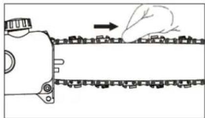
Diagram of a mechanical device emitting smoke or vapor onto a conveyor belt, with no visible text or symbols.Checking the chain tension
- Check the chain tension.
- Switch off the engine.
- Wear work gloves to protect your hands.
- The chain must lie close to the bottom of the bar, and at the same time, it must be possible to move the chain along the bar with your hand.
- Retighten the chain if necessary.
Lubricating the saw chain
For automatic and reliable lubrication of the chain and guide bar, please use only high-quality and environmentally friendly lubricating oil with an adhesive additive.
The maintenance requirement depends on lubricating oil quality. It is, therefore, essential to use only designated chain lubricating oil.
Top up 20 grams of grease/lubricant every 25 operating hours.
If no chain lubricating oil is available, you can use an HD single-grade or multi-grade engine oil with a viscosity appropriate to the outside temperature in an emergency.
natural_image
Diagram showing a hand pressing down on a mechanical component with a magnified view (no text or symbols)Do not use used oil!
Medical studies have shown that contact with used oil can lead to skin cancer. Furthermore, waste oil is harmful to the environment!
Used oil no longer has the necessary lubricating properties and is unsuitable for lubricating the chain.
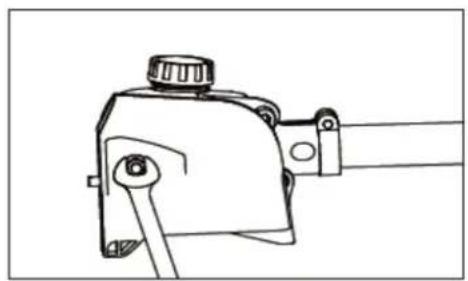
Filling oil for the chain
- Check the oil level regularly during work. Never let it run out!
- Clean the tank cap and its surroundings so that no dirt falls into the tank.
- Place the device so that the tank cap is facing upwards.
natural_image
Technical line drawing of a mechanical component with no visible text or symbolsIf the oil level in the tank does not drop, there may be a problem in the oil supply:
Check the lubrication condition of the chain, clean the oil lines, and contact your dealer if necessary.
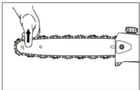
Checking the lubrication of the chain
The chain saw must always fling a small amount of oil from itself.
- Always check the lubrication of the chain and the oil level in the tank before starting work.
natural_image
Diagram of a chain-linking device emitting arrows, showing motion direction (no text or symbols)Never use your saw without lubricating oil. If the chain dries out, the entire cutting tool will be permanently damaged in a short time.
Each new chain must be run in for 2 to 3 minutes. Then check the chain tension and adjust it if necessary (see section "Checking the chain tension").
Using the branch saw attachment
Preparation
- Wear suitable protective clothing and equipment - see "Safety Instructions."
- Start the engine
- Put on the shoulder strap
Do not throw the cuttings into the household waste, they can be composted!
Never stand under the branch you are sawing off. Watch out for falling branches and twigs. Be aware that they could hit you after impact.
Cutting procedure
Always cut the lower branches first so that they can fall down freely. Cut thick branches in small, controllable portions.
Working posture
Hold the wrap-around handle with your left hand and with your right hand the throttle handle. Your left arm should be stretched out in one of the most comfortable positions for you.
The axle should always be held at an angle of no more than 60^ !
The most comfortable working position is with the tool at a 60^ angle. Still, smaller angles are also possible, depending on the situation.
Cross-cutting
To avoid jamming the guide rail in the cutting gap, place the tool with the hook against the branch, and then perform the cross-section from top to bottom.
natural_image
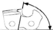
Illustration of a chain-linking tool with a circular base, no text or symbols presentThe relief cut
To avoid splintering the bark on thick branches, always start with a relief cut (1) on the lower side of the branch.
- To do this, guide the saw in an arc through the underside of the branch (see illustration).
- Then place the hook against the branch and make the cross-cut (2).
Cut thick branches flush
If the branch diameter is more than 10 cm, first cut it with relief and cross-section (3) at a distance (A) of about 20 cm from the actual target.
- Then you can cut the branch flush (4) through relief and subsequent cross-section.
text_image
Technical diagram showing a mechanical linkage or lever mechanism with labeled components 1 and 2, including a shaded circular component.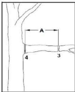
text_image
A 4 3Cutting over obstacles
The long reach allows the cutting of branches and twigs hanging over obstacles such as rivers or ponds.
The angle of the tool depends on the position of the branches and twigs.
Reactive forces
Reactive forces occur during the operation of the saw-chain. The forces that are to be applied to the wood act against the user. They happen when the running chain comes into contact with a solid object such as a branch or is jammed. These forces can lead to a loss of control and injuries as a result. Understanding the origin of these forces can help you avoid the fright and loss of control.
This saw is designed so that the kickback effects are not as noticeable as with conventional chainsaws.
Nevertheless, always keep a firm grip and an excellent stance to maintain control of the tool in case of doubt.
The most common effects are:
- kickback,
- Recoil,
- Retreat.
Kickback
Kickback may occur if the running saw-chain hits or is jammed against a solid object at the upper quarter of the guide bar.
The cutting force of the chain exerts a rotational force on the saw in the opposite direction to the chain movement. This results in an upward movement of the guide bar.
natural_image
Diagram of a curved road with a circular object and directional arrow, no text or symbols presentAvoiding kickback
The best protection is to avoid situations that lead to setbacks.
- Always keep an eye on the position of the top guide rail.
- Never let this point come into contact with an object. Do not cut it. Be especially careful near wire fences and when cutting small, hard branches where the chain can easily get caught.
- Only cut one branch at a time.
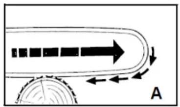
The retraction (A) occurs when the chain suddenly becomes stuck on the underside of the bar because it is jammed or hits a foreign object in the wood. The chain then pulls the saw forward. The retraction often occurs when the chain does not run at full speed when it comes into contact with the wood.
A = Retraction
natural_image
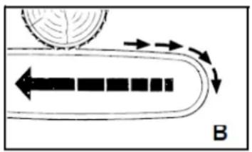
Diagram showing a curved object with arrows indicating motion or flow, no text or symbols presentAvoid retraction B = Kickback
Be aware of the forces and situations that can cause the chain to jam at the bottom of the bar.
- Always start cutting with the chain running at full speed. Recoil (B) occurs when the chain is suddenly stuck on the top of the bar because it is jammed or hits a foreign object in the wood.
The chain can then press the saw against the operator with a jerk. Kickback often occurs when the bar top is used for cutting.
natural_image
Diagram showing a curved path with directional arrows and a circular element, labeled 'B' (no text or symbols beyond label)Avoid kickback
- Be aware of the forces and situations that can cause the chain to jam on the top of the bar.
- Do not cut more than one branch at a time.
- Do not tilt the bar sideways when pulling it out of a cutting gap, as the chain could be jammed.
During operation
Check the chain tension regularly!
A new chain must be re-tensioned more often than an older one.
Cold chain:
Tension is correct when the chain is close to the bottom of the bar and can still be pulled along the bar by hand.
Retighten if necessary (see section "Tensioning the saw-chain").
The chain at operating temperature:
The chain expands and begins to sag. The dynamic links on the bottom of the bar should not fall out of the groove. Otherwise, the chain will fall off the bar.
Retighten the chain (see section "Tensioning the saw-chain").
After work
Loosen the chain if you have tightened it while working at operating temperature.
The chain contracts when it cools down. If it does not loosen, it may cause damage to the gear wheel and bearing.
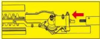
Guide bar maintenance
- Turn the bar over each time you have sharpened or replaced the chain. This will prevent uneven wear of the bar, especially at the top and bottom. Clean regularly
1 = the opening for the oil supply
2 = the oil duct
3 = the running groove of the rail
text_image
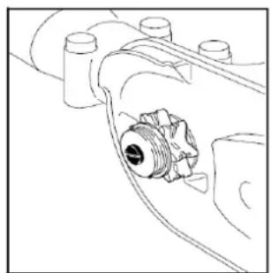
Technical diagram of a mechanical device with labeled parts and a close-up view showing internal components.Checking and replacing the sprocket
- Remove the sprocket cover, chain, and guide bar.
Replace the sprocket:
– at the latest after the service life of two chains or before.
- when the wear marks on the sprocket are more deep-seated than 0.5mm . Otherwise, the service life of the chain would be reduced.
You can extend the life of your sprocket by using two chains alternately.
natural_image
Technical line drawing of a mechanical assembly with no visible text or symbolsMaintenance and sharpening of the saw chain
The correctly sharpened chain
An adequately sharpened chain goes effortlessly through the wood and requires very
little pressure. Do not work with a dull or damaged saw-chain. It increases physical strain, increases vibrations, and leads to unsatisfactory results and higher wear and tear:
- Clean the chain.
- Check it for broken links and damaged rivets.
- Replace damaged and worn chain parts with suitable spare parts, which you can file to the shape and size of the original parts if necessary.
Observe the angles and dimensions given below. If the saw chain is not sharpened correctly or the depth gauge is too small, there is a higher risk of kickback effects and resulting injuries!
The saw chain cannot be fixed on the guide bar. It is, therefore, best to remove the chain from the guide bar and then sharpen it.
- Select a sharpening tool suitable for chain pitch. See "Technical data" for the approved chain pitches.
The chain pitch (e.g., 3/8") is marked in the depth gauge of each blade.
Only use particular files for saw chains!
Other files have the wrong shape and grinding.
Choose the diameter of the file according to your
Chain pitch. Please also note the following
Angling when sharpening the chain knives.
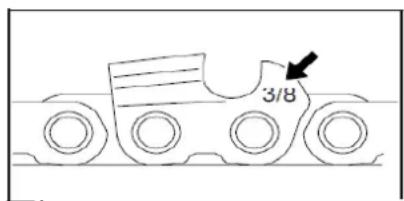
text_image
3/8A
B
A = filing angle
B = angle of the side plate
The angle must also be maintained for all knives. If the angle is uneven, the chain will run irregularly, wear out quickly, and break prematurely.
As these requirements can only be met with sufficient and regular practice:
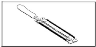
natural_image
Line drawing of a mechanical tool or tool with no visible text or symbols- Use a file holder A file holder must be used when sharpening the saw-chain by hand. The correct file angles are marked on it.
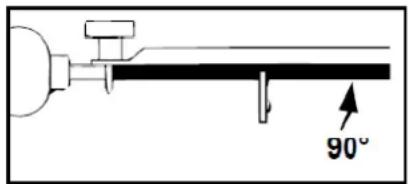
text_image
90°- Hold the file horizontally (at the correct angle to the guide bar) and file according to the angle mark on the file holder. Support the file holder on the top plate and the depth gauge.
natural_image
Pure mechanical component diagram without any text, numbers, or symbols• Always file the blade from the inside out.
- The file sharpens only in the forward movement. Lift it off when moving backward.
- Do not touch the fastening straps and dynamic links with the file.
- Continue to rotate the file regularly to prevent uneven wear.
- Use a piece of hardwood to remove bones from cut edges.
All knives must be of the same length. Otherwise, they will be of different heights. This makes the chain run irregularly and increases the risk of breaking.
35. Using the 1m extension for MT152E
The extension is mounted in the same way as the other attachments:
1). Place the drive axle against the main shaft so that the hole of the axle is aligned with the locking pin of the connecting piece.
2). Actuate the locking pin and insert the drive axle into the main shaft. Release the locking pin and ensure that the locking pin engages in the hole.
3). Turn the wing screw clockwise to secure the connection.

natural_image
Mechanical assembly diagram showing a lever mechanism with a handle and base mount (no text or symbols)
natural_image
Close-up of a hand holding a metallic cylindrical tool with arrows indicating movement or force (no text or symbols visible)
natural_image
Hand holding a mechanical tool with a metallic handle and black grip (no text or symbols visible)Use the 1-meter extension:
The 1-meter extension can be used with all attachments are mounted in between and serves to protect t increase in your working radius.
36. Using the pivoting branch saw attachment on the
MT252
IMPORTANT: Do not mount or adjust the attachment unless the device is turned off.
The mounting of the swiveling branch saw attachment is the same as for the other accessories:
1). Place the drive axle against the main shaft so that the hole of the axle is aligned with the locking pin of the connecting piece.

natural_image
Mechanical assembly diagram showing a lever mechanism with a handle and base mount (no text or symbols)2). Actuate the locking pin and insert the drive axle into the main shaft. Release the locking pin and ensure that the locking pin engages in the hole.

natural_image
Close-up of a hand holding a metallic cylindrical tool with arrows indicating movement or force (no text or symbols visible)3). Turn the wing screw clockwise to secure the connection.

natural_image
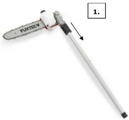
Hand holding a metallic tool with a handle, against a plain white background (no text or symbols visible)Use the pivoting branch saw attachment:
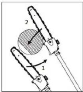
Step one: Pull the black handle downwards for adjustment.
Step two: Adjust the tilt angle of the branch, saw attachment as desired.
natural_image
Close-up of a FUXTEC tool with a metallic handle and black base, labeled '1.' (no text or symbols on the tool itself)
natural_image
Close-up of a Fuxtev chain saw with orange jaw and black handle, showing blade and tool (no text or symbols on the saw itself)37. Starting/stopping the device
Cold start
- Place the device on a firm and flat surface.
Slide the engine stop switch to " I " in the direction of the engine.

- Move the choke lever upwards to "COLD START."
- Press the carburetor pump about 8-10 times (until gasoline flows in the line)
- Pull out the starter rope with a short-stroke until resistance is felt (about 100mm). A continuous, mainly fast train will provide a strong spark and let the engine report.

natural_image
Close-up of a black 3D printer with orange base and orange handle, showing mechanical components and a red arrow indicating motion (no text or symbols)
natural_image
Close-up of a hand adjusting a black industrial air conditioner unit with orange clamps (no visible text or symbols)- Important: As soon as the engine has responded, set the choke lever to the "WARM START" position and pull the starter immediately until the engine starts.
- Let the engine warm-up at idle for about 10 minutes NOTE: If the device does not start after repeated attempts, refer to troubleshooting
chapters.
NOTE: Always pull the starter cord straight out. Pulling the starter at an angle will cause the rope to rub against the eyelet. Pulling the starter at an angle can cause the starter cable to fray or break. Always hold the starter handle firmly when the rope is pulled back. Never allow the rope to be thrown back from the pulled-out position. This could damage the starter device.
Warm start of the engine
- Place the device on a firm and flat surface.
- Slide the engine stop switch down
- Slide the choke to the "WARM START" position
- Pull out the starter rope with a short-stroke until resistance is felt
(about 100mm). A continuous high-speed train will provide a strong spark and start the engine
If the device does not start, please proceed again according to "Cold start of the engine
Stopping the device
Unlock the throttle. Let the device return to idle. Push the engine stop switch on the handle upwards until the device stops. If it does not stop, pull out the spark plug connector in an emergency. Never leave the device unattended while it is running.
38. Refueling the engine
FUEL AND 2-STROKE OIL
Use unleaded gasoline with 2-stroke engine oil in a 40:1 ratio. During the first few operations, a mixture ratio of 25:1 can be selected to initially lubricate all device parts optimally.
WARNING: Never use pure gasoline in your engine. This will cause permanent engine damage and voids the manufacturer's warranty for this product. Never use a fuel mixture that has been stored for more than 90 days.
WARNING: This must be a premium grade, 2-stroke air-cooled engine oil.
FUEL MIXTURE
Mix fuel with 2-stroke oil in a container provided for this purpose. Note the following the mixture table on the following page for the correct fuel/oil ratio. Shake the tank to ensure complete mixing.
| Gasoline | Two-stroke engine oil (40:1) | Gasoline | Two-stroke engine oil (40:1) |
| 1 liter | 0.025 liters | 5 liters | 0.125 liters |
| 2 liters | 0.050 liters | 10 liters | 0.250 liters |
WARNING: Failure to lubricate the device eliminates the liability of the device manufacturer.
Gasoline and oil must not be mixed in a ratio of more than 40:1.
Recommended fuel
It is recommended to use unleaded gasoline with an octane number of 90 # or higher to reduce carbon deposition in the combustion chamber. Do not use old or dirty gasoline. Keep the fuel tank dust-free and avoid water getting into the tank. Sometimes misfiring will occur under usual overload.
If the backfiring is heard under average load, we recommend replacing the gasoline. If the misfire is still present afterward, please contact an authorized workshop.

WARNING
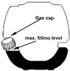
text_image
Gas cap max. filling level● Gasoline is highly flammable and can cause an explosion in the case of sparks.
- Refuel only in well-ventilated rooms and allow the engine to cool down before filling. Smoking and open fire, as well as any sparks, must be avoided during refueling.
- Do not overfill the tank (see figure max. filling level).
● After refueling, check that the fuel filler cap is closed correctly.
- Avoid any spillage of gasoline.
- Keep the device away from children.
39. Trimming techniques
CAUTION
IF YOU are NOT familiar with the trimming techniques, practice with the DEVICE in the "STOP" position (turned off).
ALWAYS TRIM OR CUT AT HIGH ENGINE SPEEDS. Do not run the device slowly at the start or in trim mode.
ALWAYS MAKE DISTANCE IN THE WORKING AREA from cans, bottles, rocks, etc.
Whirling objects can cause serious injury to users or bystanders and damage the device.
If an object is accidentally knocked, immediately stop the DEVICE and check the device.
Never run the device with damaged or defective parts.
DO NOT use the device for any purpose other than trimming grass.
Never lift the nylon cutting head above knee height during operation.
Do not run the device on a slope if there is a chance of slipping or losing stability.
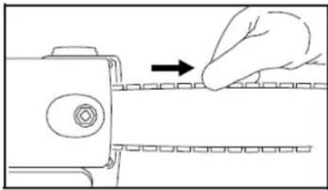
RELEASING THE NYLON THREAD

To release fresh thread, run the device at full throttle and tap the nylon cutting head onto the lawn. The thread releases automatically. The blade in the protective shield cuts off excess thread.

CAUTION: Remove grass deposits regularly to prevent overheating of the drive axle. Grass deposits occur when fibers of the weed become entangled around the shaft under the protective shield. This prevents the shaft from
cooling correctly. Remove grass deposits with a screwdriver or similar tool only when the device is switched off.
natural_image
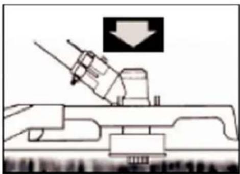
Diagram of a naval gun firing with a downward arrow indicating speed (no text or symbols present)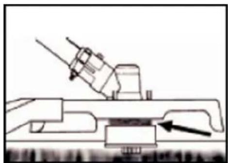
natural_image
Technical line drawing of a mechanical assembly with an arrow indicating a component (no text or symbols present)When the device is appropriately equipped with a protective shield and nylon cutting head, your device will trim unsightly weeds and large diameter tall grass in areas along fences, walls, land, and around trees.
NOTE: Pay particular attention when trimming on brick or stone walls, etc., where rapid
weed wear will occur.
TRIM MORE ACCURATELY
Swing the trimmer's nylon cutting head horizontally from side to side. Do not tilt the nylon cutting head while working. For correct cutting height, trim in a test area beforehand. Keep nylon cutting head at the same level for even depth of cut.
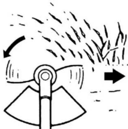
TRIMMING AROUND TREES
Trim around logs with a slow approach; the thread should not collide with the log. Walk around the tree from left to right—approach grass or weeds with the tip of the thread.
natural_image
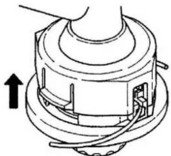
Diagram of a mechanical device emitting smoke or vapor, with arrows indicating direction (no text or symbols)40. Replacing Nylon Thread
- Switch off the engine
- Place the trimmer on the ground so that the drive axle with the spool is exposed and remove the nylon head
- Open the nylon head by pressing the release
- Cut the new thread to 5m and wind it tightly clockwise around the thread take-up device

natural_image
Close-up of hands holding a small metal object with a wire, no visible text or symbols
natural_image
Close-up of hands holding a black mechanical component (no visible text or symbols)-
Remove the superfluous thread
-
After the thread take-up device is wrapped, attach the thread ends as shown in the illustration

natural_image
Close-up of a hand holding a black mechanical component with wires extending from it, against a cloudy sky background (no text or symbols visible)
natural_image
Close-up of hands holding a black cylindrical object (no visible text or symbols)-
guide the thread ends through the holes in the outer part of the bobbin
-
Press the inner and the external coil together and turn them against each other until they engage
natural_image
Technical line drawing of a mechanical assembly with no visible text or symbols41. Maintenance plan
Regular checks and adjustments must be made to ensure that the gasoline engine maintains its performance. Periodic maintenance also provides a long service life. See the following table for the regular maintenance cycle.
| Maintenance cycle Component | Each use | Every month or 10h | Every 3 months or 25h | Every 6 months or 50h | Every 12 months or 100h | Every 2 years or 300h | |
| Lubricating oil | Check oil level | ■ | |||||
| Refill | 20g every 25h | ||||||
| Exchange | ■ | ■ | |||||
| Air filter | Check | ■ | |||||
| Clean up | ■a | ||||||
| Spark plug | Check & adjust | ■ | |||||
| Exchange | ■ | ||||||
| Spark plug connector (optional) | Clean up | ■ | |||||
| Cooling fins | Audit | ■ | |||||
| connecting elements such as screws and nuts | Check (tighten if necessary) | ■ | |||||
| Coupling | Audit | ■b | |||||
| Idle speed | Check and adjust | ■b | |||||
| Valve clearance | Check and adjust | ■b | |||||
| Combustion chamber | Clean up | 300 h after that | |||||
| Fuel | Check | ■ | |||||
| Fuel tank | Check | ■ | |||||
| Fuel line | Check | Every x years (replace if necessary) | |||||
WARNING

a. Increase maintenance intervals if working in dusty environments.
b. All maintenance work - except for that listed in the operating manual - must be carried out at regular intervals.
Work must be carried out by qualified maintenance personnel
Cleaning the air filter
CAUTION: Never run the engine without the air filter.
A dirty air filter puts pressure on engine performance, increases fuel consumption, and makes starting more difficult. If you notice a loss of engine power:
1 Remove the screw on the filter cover and take out the filter.
2 Clean the filter with soap and water. Never use gasoline or benzene!
3 Let the filter dry in the air.
4 Put the filter back in place and fasten the filter cover with the screw

natural_image
Close-up of a hand adjusting a black FUTTEC brand air purifier with orange handle (no visible text or symbols)
natural_image
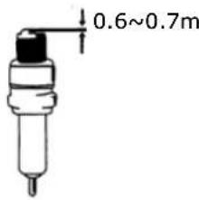
Close-up of a black and orange industrial device with internal components, showing no visible text or symbols.Spark plug maintenance
To ensure the normal operation of the engine, the ignition distance of 0.6 -0.7mm must be maintained and must be free of carbon deposits. Always carry out the following steps with the engine switched off:
- Carefully remove the spark plug connector. Do not pull on the cable but directly on the plug
-
Use the spark plug wrench supplied to unscrew the spark plug
-
Visually check the spark plug for damage and electrode burn-off,
Remove the carbon deposits
- Check the gap with a feeler gauge and bend the electrode to the correct
distance of 0.6 to 0.7mm
- Check the spark plug washer and tighten the spark plug with a torque of
12-15 Nm
- Fit the ignition cap back onto the spark plug
text_image
0.6~0.7mWARNING

The spark plug must be screwed down tightly; otherwise, the engine runs hot and is damaged.
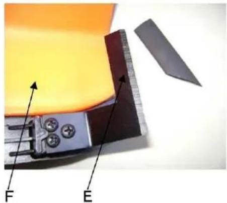
Sharpen the shield knife
- Remove cutting blade (E) from a protective shield (F).
- Clamp the knife in a vice. Sharpen the knife with a flat-file. Please make sure that you maintain the angle of the cutting edge. Only move the sharpening knife in one direction during the sharpening process.
Warning!
If adjustments to the carburetor have to be made, this must be carried out by a specialist workshop.
natural_image
Close-up of a mechanical component with labeled parts F and E, showing internal components and a ruler-like structure (no readable text or symbols beyond labels)42. Storage of the device

WARNING: Failure to follow these steps may result in the formation of deposits in the carburetor. This will make starting difficult and cause permanent damage
- Perform all general maintenance as described in the maintenance section of your user manual are recommended.
- Clean the exterior of the device, drive axle, protective shield, and nylon cutting head.
- Drain fuel from the fuel tank.
- After draining fuel, start the engine.
- Let the device run in neutral until the device stops on its own. This will clean the carburetor of fuel.
- Let the device cool down (about 5 minutes).
- Use a spark plug wrench, remove the spark plug.
- Pour 1 teaspoon of clean 2-stroke oil into the combustion chamber. Pull the starter cord
slowly several times to coat internal components. Replace the spark plug.
- Store the device in a cool, dry place away from any ignition source such as an oil burner, water heater, etc.
TRANSPORT PROTECTION
Make sure that the device is well-secured during transport to avoid fuel loss, damage, or injury. Install transport protection for metal sheets during transport and storage
43. Troubleshooting
- Difficulties during commissioning
| Situation | Cause | Solution | |
| No ignition spark | Spark plug | Carbon deposit between the diodes of the spark plug | Clean the spark plug. Adjust the gap 0.6~0.7mm, Replace the spark plug |
| other | ignition coil defective flywheel magnet too weak | Replacing the ignition coil or flywheel | |
| Weak ignition spark | Compression | Too much gasoline in the combustion chamber, bad fuel or water in the tank | Remove the spark plug and allow to dry, replace fuel. |
| The carburetor does not pump oil anymore. | Oil line blocked | Cleaning the carburetor and cleaning the pipes | |
| regular oil supply but weak compression | Piston rings worn, spark plug not screwed down, cylinder head not tight wrong valve clearance or ignition timing. | Replace screw tight replace or adjust | |
| Regular oil supply and proper ignition spark | Poor contact between ignition cap and spark plug | Replace or check | |
2. Difficulties during operation
| Situation | Cause | Solution |
| The engine does not reach the speed | Choke is in "COLD START" position, an exhaust system is blocked no air supply, moving elements worn, ignition spark weak too large valve clearance, cylinder head sooty | Open choke, replace exhaust system Check or replace ignition coil, adjust flywheel, spark plug |
| Operating materials are leaking | Lines to carburetor blocked Spark plug spacing incorrect | Replace the lines and, if necessary, the carburetor; adjust gap dimension |
| Engine-Noises | Wrong choke position, Camshaft damaged | Check/replace camshaft |
| Carburetor leaking | Failure of the check valve on the tank cap | Replace the fuel filler cap |
| Carburetor gasket is worn out | Replace carburetor or gasket |

If no troubleshooting solves the problem, contact your dealer or the manufacturer directly. Only use original parts approved by the manufacturer. Otherwise, there is a risk of danger.
44. INFO: Optional accessories (adjustable pole saw)
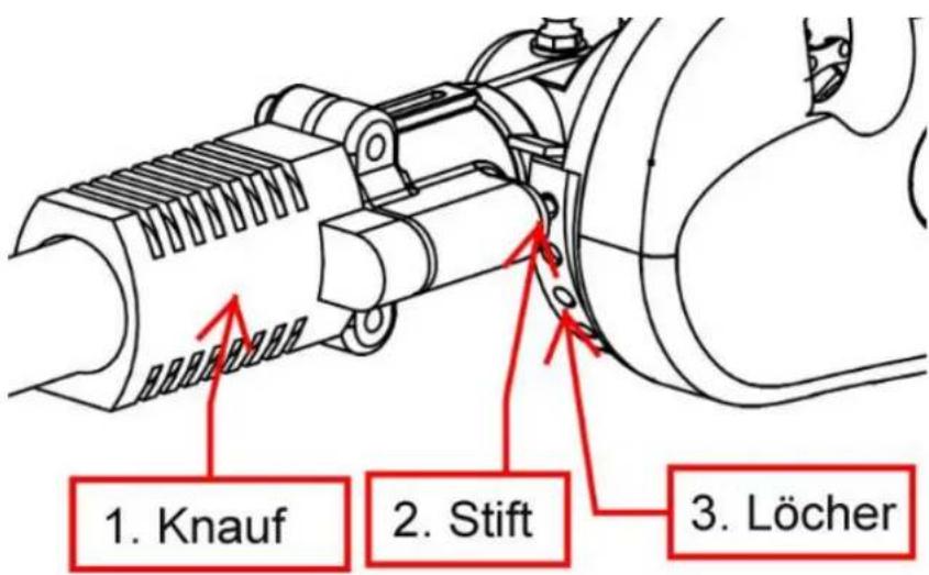
Assembly: Pull the knob back and position the desired angle on the attachment and release the knob so that the pin can engage in one of the holes.
45. Customer Service
Have your purchased device repaired only by qualified personnel and only with original spare parts. This will ensure that the safety of the device is maintained.
If you do not have the addresses of authorized service centers, please contact the sales office where you purchased the device. Please contact the manufacturer FUXTEC GmbH directly at www.fuxtec.de at any time regarding maintenance work and the procurement of spare parts.
46. Warranty
The warranty period is 24 months from the date of purchase. Please keep your proof of purchase in a safe place. Excluded from the warranty are wearing parts and damage caused by improper use, use of force, technical modifications, use of incorrect accessories or non-original spare parts, and repair attempts by non-qualified personnel. Warranty repairs may only be carried out by authorized specialist dealers.
47. Disposal note
Please contact your local municipality for the disposal of the device. Please dispose of all operating materials such as gasoline and oil in advance.
48. EC Declaration of Conformity
We hereby declare,
FUXTEC GMBH
CAPPING ROAD 69, 71083 HERRENBERG, GERMANY
that the device described below, by its design and construction and in the version marketed by us, complies with the relevant essential health and safety requirements of the EC directives.
Designation of the device:
Multi-function cutter
Engine type:
FX-MT152/-MT152E/-MT252E
Trademark:
FUXTEC
Power
52cm ^3
consumption/displacement
Measured sound power level
LWA = 107.7dB
Guaranteed sound power level
LWA=111dB
Conformity procedure
2000/14/EC according to Annex
IV
Relevant EC guidelines:
EC device straightening thread 2006/42/EG
EC directive thread on electromagnetic compatibility (EMC)
2014/30/EU
EC-directive thread Noise emission (2000/14/EG & 2005/88/EG)
applied harmonized EN ISO 11806-1
Standards:
EN ISO 11680-1
EN ISO 10517; EN ISO 14982
Manufacturer signature/date:
C. Fille
Leonhard Zirkler, 02.12.2022
the name and address of the
Leonhard Zirkler
person authorized to compile the
FUXTEC GMBH - KAPPSTRAße 69, 71083 HERRENBERG,
technical documentation
GERMANY
established within the
Community
MODE D'EMPLOI ORIGINAL
FX-MT152/-MT152E/-MT252E

natural_image
Product photo of various manual tools including a shovet, saw, and power tools (no text or symbols visible)CE
natural_image
Person wearing a white shirt and black pants holding a portable machine with orange grip (no visible text or symbols)Attention
text_image
Labeled diagram of a manual tool set with numbered parts for identificationnatural_image
Close-up of a black mechanical device with orange handle and 'PATEL' label, no readable text or symbols beyond the labelnatural_image
Two labeled mechanical devices: a left with a pointer and a black-and-orange base, and a right with a handle (no text or symbols visible)natural_image
Black mechanical device with handle and base, labeled 'Gummimuffel + 4 Imbussschrauben M5x35' (no other text or symbols visible)
natural_image
Close-up of a black and white mechanical tool with a handle and lever mechanism (no text or symbols visible)natural_image
Mechanical assembly diagram showing a lever mechanism with a black base and arrow indicating direction (no text or symbols)natural_image
Close-up of a hand holding a metallic cylindrical tool with arrows indicating movement or force (no text or symbols visible)natural_image
Hand holding a metallic tool with a handle, against a plain white background (no text or symbols visible)natural_image
Close-up of a black and orange robotic brush tool with a metallic handle, no visible text or symbols
natural_image
Close-up of a black industrial fan or support structure with a metallic handle and circular component (no visible text or symbols)
text_image
2 3 4
natural_image
Two-step diagram showing a mechanical tool being inserted into a gear-like component, with no visible text or symbols.text_image
Attention! 1 2Attention!
natural_image
Line drawing of a person walking with a tool, no text or symbols presenttext_image
Technical diagram of a mechanical tool with numbered parts, showing a hatched blade assembly and orange base strips.Explication
- Lames de coupe
natural_image
Line drawing of a worker using a manual shoveling material on a paved surface (no text or symbols)Préparation
text_image
Technical diagram of a mechanical tool with labeled parts, showing hands operating a tool and connecting components.natural_image
Line drawing of a person walking with a long tool, no text or symbols presentnatural_image
Line drawing of a person using a long-handled tool outdoors, with trees and grass in the background (no text or symbols)natural_image
Illustration of a person holding a long tool, wearing a helmet and gloves (no text or symbols)natural_image
Technical line drawing of a mechanical device with no visible text or symbols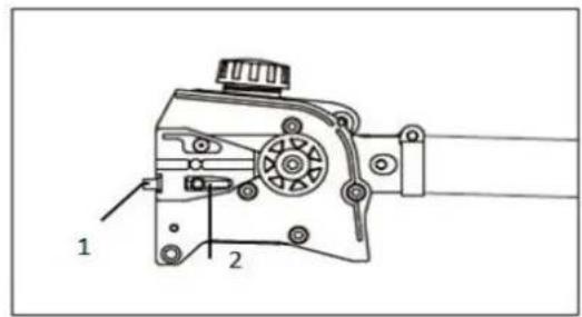
text_image
Technical diagram of a mechanical device with labeled parts 1 and 2natural_image
Diagram of a mechanical device emitting smoke or vapor onto a conveyor belt, with no visible text or symbols.natural_image
Line drawing of a hand pressing down on a mechanical component with a magnified view (no text or symbols)natural_image
Technical line drawing of a mechanical device with rollers and housing (no text or symbols)natural_image
Diagram of a chain-linking device emitting arrows, showing motion direction (no text or symbols)natural_image
Diagram of a diagonal saw cutting a circular object, no text or symbols presenttext_image
Technical diagram showing a mechanical linkage system with labeled components 1 and 2, including a shaded circular area.natural_image
Simple line drawing of a curved road with a circular object on the left, no text or symbols present.natural_image
Diagram showing a curved path with directional arrows and a circular element, labeled B (no text or symbols)text_image
Technical diagram of a mechanical device with numbered parts labeled 1, 2, and 3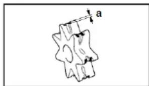
natural_image
Pure mechanical part diagram without any text, numbers, or symbolsnatural_image
Technical line drawing of a mechanical assembly with no visible text or symbolsnatural_image
Line drawing of a folding tool with handle and blade (no text or symbols)- Utiliser un porte-lime
natural_image
Simple line drawing of a mechanical component with a central circular feature and two circular holes (no text or symbols)natural_image
Mechanical assembly diagram showing a lever mechanism with a handle and base mount (no text or symbols)natural_image
Close-up of a hand holding a metallic pipe fitting with arrows indicating direction (no text or symbols visible)natural_image
Hand holding a metallic tool with a handle, against a plain background (no text or symbols visible)natural_image
Mechanical assembly diagram showing a lever mechanism with a handle and base mount (no text or symbols)natural_image
Close-up of a hand holding a metallic pipe fitting with arrows indicating direction (no text or symbols visible)natural_image
Hand holding a metallic tool with a handle, no visible text or symbolsnatural_image
Close-up of a FUKTEC chain saw with orange blade and black handle, showing tool movement arrows (no text or symbols on the saw itself)natural_image
Mechanical assembly with red arrow indicating direction, no visible text or symbols
natural_image
Close-up of a mechanical component with orange plastic parts and a red arrow indicating a specific part (no text or symbols visible)
natural_image
Close-up of a mechanical component with orange and black parts, no visible text or symbolsnatural_image
Close-up of a black industrial air purifier with orange base, showing mechanical components and a hand holding the top part (no text or symbols visible)
natural_image
Close-up of a hand adjusting a black and orange industrial machine component with a red arrow indicating the adjustment (no visible text or symbols)natural_image
Technical line drawing of a naval gun on a ship deck with an arrow indicating downward motion (no text or symbols)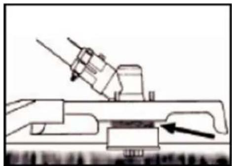
natural_image
Technical line drawing of a mechanical assembly with an arrow indicating a component (no text or symbols present)natural_image
Diagram of a mechanical fan or impeller with motion arrows indicating flow or movement (no text or symbols)DÉCOUPAGE AUTOUR DES ARBRES
natural_image
Close-up of hands holding a small mechanical component with a wire, no visible text or symbols
natural_image
Close-up of hands holding a black mechanical component (no visible text or symbols)natural_image
Close-up of a hand holding a black mechanical component with wires, no visible text or symbols
natural_image
Close-up of hands holding a black cylindrical object (no visible text or symbols)natural_image
Technical line drawing of a mechanical assembly with no visible text or symbols65. Plan de maintenance
natural_image
Close-up of a hand adjusting a black and orange electronic device component with visible wiring (no text or symbols)
natural_image
Close-up of a black and orange industrial device with internal components, showing no visible text or symbols.text_image
0.6~0.7mmAVERTISSEMENT
natural_image
Close-up of a mechanical component with labeled parts F and E, showing internal components and a cutting tool (no text or symbols beyond labels)Attention!
natural_image
Product photo of various manual tools including a shovet, saw, and power tools (no text or symbols visible)CE
natural_image
Person wearing a white shirt and black pants holding a small electric shaver tool, standing against a plain white background (no text or symbols visible)Attenzione
text_image
Labeled diagram of a manual tool with numbered parts for identificationnatural_image
Close-up of a black mechanical device with orange handle and black strap, labeled 'PATEL' and number '19' (no readable text or symbols beyond labels)Solo per MT152E:
Solo per MT252:

natural_image
Close-up of a metallic tool with a label 'Furney' on its tip, no other text or symbols visible.natural_image
Close-up of a black mechanical device with a handle and cylindrical shaft, labeled 'Protezione in gomma +4 viti a brugola M5X35' (no other text or symbols visible)
natural_image
Close-up of a black and white mechanical tool with a handle and lever mechanism (no text or symbols visible)Montaggio accessori
natural_image
Mechanical assembly diagram showing a lever mechanism with a handle and pivot point (no text or symbols)
natural_image
Close-up of a hand holding a metallic cylindrical tool with arrows indicating movement or adjustment (no text or symbols visible)
natural_image
Hand holding a metallic tool with a handle, against a plain white background (no text or symbols visible)natural_image
Close-up of a black robotic brush with orange frame and mechanical lever (no text or symbols visible)natural_image
Diagram of a mechanical component with a circular base and orange outline, labeled with number 3 (no text or symbols on the object itself)

natural_image
Close-up of a mechanical tool with a black blade and orange base, being adjusted by hand (no text or symbols visible)
natural_image
Close-up of hands installing a mechanical component with a wrench, no visible text or symbolsnatural_image
Line drawing of a person walking with a tool, no text or symbols presenttext_image
Technical diagram of a mechanical tool with numbered parts, showing a hatched blade assembly and orange base strips.Descrizione
- Lama di taglio
natural_image
Line drawing of a person using a manual shoveling soil or gravel in a field (no text or symbols)Preparazione
text_image
Technical diagram showing hands operating a mechanical tool with labeled parts (1)natural_image
Line drawing of a person walking with a long tool, no text or symbols presentnatural_image
Line drawing of a person using a long-handled tool to cut a tree in a field (no text or symbols)natural_image
Illustration of a person holding a tool, wearing a helmet and gloves (no text or symbols)natural_image
Technical line drawing of a mechanical component with no visible text or symbols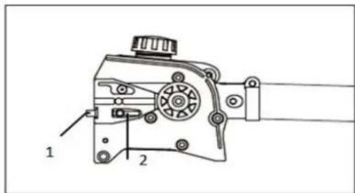
text_image
Technical diagram of a mechanical device with labeled parts 1 and 2natural_image
Illustration of a hand using a chain to cut a single tree branch (no text or symbols)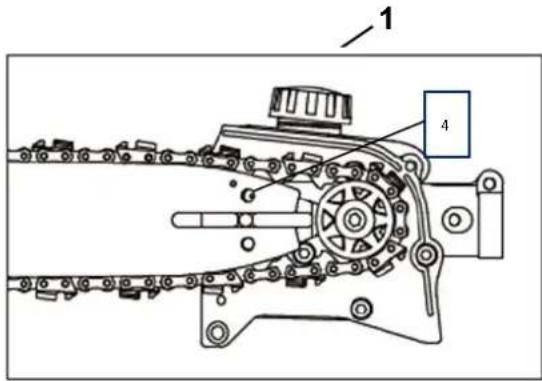
text_image
1 4natural_image
Diagram of a mechanical device emitting a leaf from a chain, showing motion direction (no text or symbols)natural_image
Line drawing of a hand pressing down on a mechanical component with a magnified inset showing the next step (no text or symbols)natural_image
Technical line drawing of a mechanical component with no visible text or symbolsnatural_image
Diagram of a chain-linking device with arrows indicating direction (no text or symbols)natural_image
Diagram of a diagonal saw cutting a circular object, no text or symbols presenttext_image
Technical diagram showing a mechanical linkage system with labeled components 1 and 2, including a shaded circular component.natural_image
Diagram of a mechanical or fluidic system with a curved pipe and circular component, no visible text or symbolsnatural_image
Diagram showing a vehicle with motion arrows and a circular object, labeled 'A' (no text or symbols on the diagram itself)Evitare l'avanzamento
B = rinculo
natural_image
Diagram showing a curved path with directional arrows and a circular element, labeled 'B' (no text or symbols beyond label)text_image
Technical diagram of a mechanical device with numbered parts labeled 1, 2, and 3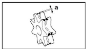
natural_image
Pure mechanical part diagram without any text, numbers, or symbols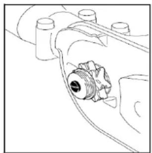
natural_image
Technical line drawing of a mechanical assembly with no visible text or symbolsnatural_image
Line drawing of a mechanical tool or tool with a handle and central body (no text or symbols)natural_image
Pure mechanical component diagram without any text, numbers, or symbolsnatural_image
Mechanical assembly diagram showing a lever mechanism with a handle and pivot point (no text or symbols)
natural_image
Hand holding a metallic pipe fitting with arrows indicating direction (no text or symbols visible)
natural_image
Hand holding a metallic tool with a black handle, against a plain white background (no text or symbols visible)natural_image
Simple line drawing of a tool with a black handle and an orange handle, no text or symbols present.natural_image
Close-up of a mechanical clamp or lever mechanism with a handle and base, showing motion direction (no text or symbols visible)natural_image
Hand holding a metallic mechanical component (no visible text or symbols)natural_image
Hand holding a metallic tool with a handle, against a plain white background (no text or symbols visible)natural_image
Two FUXTEC tools shown side by side: a metal tool and an orange chain-linking tool, both with directional arrows indicating motion (no text or symbols on the tools themselves)natural_image
Mechanical assembly with red arrow indicating direction, no visible text or symbols
natural_image
Close-up of a mechanical component with orange components and a red arrow indicating upward motion (no visible text or symbols)
natural_image
Close-up of a mechanical component with orange plastic housing and a black plastic container (no visible text or symbols)natural_image
Close-up of a black industrial device with orange base and orange handle, showing a hand holding a tool (no visible text or symbols)
natural_image
Close-up of a hand adjusting a black and orange industrial machine component with a red arrow indicating the adjustment (no visible text or symbols)natural_image
Diagram of a naval gun firing from a ship deck, showing weapon and impact symbol (no text or labels)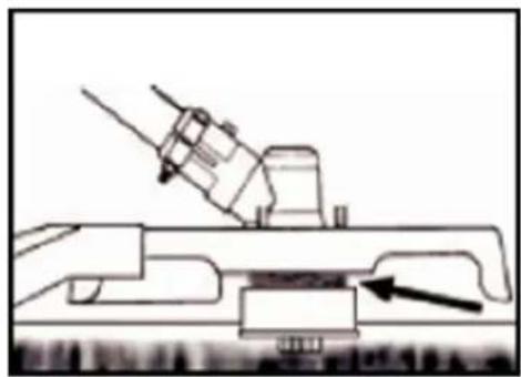
natural_image
Technical line drawing of a mechanical assembly with an arrow indicating a component (no text or symbols present)natural_image
Diagram of a mechanical device emitting particles with motion arrows indicating flow (no text or symbols)TAGLIO INTORNO AGLI ALBERI
natural_image
Close-up of hands holding a small black object with a white wire, possibly a tool or device (no visible text or symbols)
natural_image
Close-up of hands holding a black mechanical component (no visible text or symbols)natural_image
Close-up of a hand holding a black mechanical component with wires wrapped around it (no visible text or symbols)
natural_image
Close-up of hands holding a black cylindrical object (no visible text or symbols)natural_image
Technical line drawing of a mechanical assembly with no visible text or symbolsnatural_image
Close-up of a hand adjusting a black and orange electronic device component (no visible text or symbols)
natural_image
Close-up of a black industrial machine with orange hydraulic components (no visible text or symbols)
natural_image
Close-up of a black plastic electronic device with a circular component and a rectangular housing (no visible text or symbols)natural_image
Close-up of a mechanical component with labeled parts F and E, showing internal components and a ruler-like part (no readable text or symbols beyond labels)Attenzione!
natural_image
Product photo of various tools including a shovet, saw, and power tools (no text or symbols visible)CE
107.REPOSTAR EL APARATO....248
108.TÉCNICAS DE CORTE 250
natural_image
Person wearing a white shirt and black pants holding a small metal detector device (no visible text or symbols)iAtención!
text_image
Labeled diagram of a manual tool set with numbered parts for identificationnatural_image
Close-up of a black mechanical device with orange handle and black strap, labeled '19' at bottom (no readable text or symbols on device itself)Solo para MT152E:
Solo para MT252:

natural_image
Close-up of a metallic tool with a flat blade and handle, no visible text or symbolsnatural_image
Close-up of a black mechanical device with a handle and cylindrical shaft, labeled 'Protezione in gomma +4 viti a brugola' (no other text or symbols visible)
natural_image
Close-up of a black and white mechanical tool with a handle and lever mechanism (no text or symbols visible)natural_image
Mechanical assembly diagram showing a lever mechanism with a handle and pivot point (no text or symbols)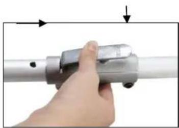
natural_image
Close-up of a hand holding a metallic cylindrical tool with a knob, no visible text or symbols
natural_image
Hand holding a metallic tool with a handle, against a plain white background (no text or symbols visible)natural_image
Close-up of a black handheld tool with orange outline and mechanical components (no visible text or symbols)
text_image
(1).
natural_image
Two-step diagram showing a tool being inserted into a mechanical component, with no visible text or symbols.natural_image
Line drawing of a person walking with a utility pole, no text or symbols presenttext_image
Labeled diagram of a mechanical tool or bracket assembly with numbered partsDescripción
natural_image
Line drawing of a person using a power tool to clean or dig outdoors (no text or symbols)Preparación
text_image
Technical diagram of a mechanical tool with labeled parts (1) and (2), showing hands operating a tool assembly.natural_image
Line drawing of a person walking with a long tool, no text or symbols presentnatural_image
Line drawing of a person using a long-handled tool to cut a tree branch (no text or symbols)natural_image
Line drawing of a person holding a long-handled tool, standing on grass (no text or symbols)natural_image
Technical line drawing of a mechanical component with no visible text or symbols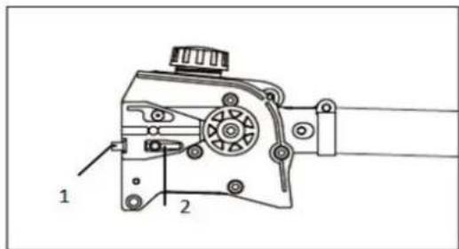
text_image
Technical diagram of a mechanical device with labeled parts 1 and 2natural_image
Illustration of a hand using a chain to cut a single tree branch (no text or symbols)
text_image
1 4natural_image
Diagram of a mechanical assembly with chains and a hand holding a leaf (no text or symbols)natural_image
Technical line drawing of a mechanical device with no visible text or symbolsnatural_image
Diagram of a chain-linking device emitting arrows, showing motion direction (no text or symbols)natural_image
Diagram of a diagonal saw cutting a circular object, no text or symbols presenttext_image
Technical diagram showing a mechanical linkage system with labeled components 1 and 2, including a shaded circular component.natural_image
Diagram of a mechanical or fluid system with a curved pipe and circular component, no visible text or symbolsnatural_image
Diagram showing a curved path with directional arrows and a circular element, labeled 'B' (no text or symbols beyond label)text_image
Technical diagram of a mechanical device with numbered parts labeled 1, 2, and 3natural_image
Technical line drawing of a mechanical assembly with no visible text or symbolsnatural_image
Line drawing of a mechanical tool or tool with a handle and internal structure (no text or symbols)natural_image
Pure mechanical component diagram without any text, numbers, or symbolsnatural_image
Mechanical assembly diagram showing a lever mechanism with a handle and base, no text or symbols presentnatural_image
Close-up of a hand holding a metallic mechanical component with arrows indicating direction (no text or symbols visible)natural_image
Hand holding a metallic tool with a handle, against a plain white background (no text or symbols visible)natural_image
Mechanical assembly diagram showing a lever mechanism with a tool and pivot point (no text or symbols)natural_image
Close-up of a hand holding a metallic cylindrical tool with directional arrows indicating movement (no text or symbols visible)natural_image
Hand holding a metallic tool with a handle, against a plain white background (no text or symbols visible)natural_image
Close-up of a metallic FUXTEC tool with a handle and black grip, isolated on white background (no text or symbols visible)
natural_image
Close-up of a FOXTEC tool with orange handle and black handle, showing blade geometry and directional arrows (no text or symbols on the tool itself)natural_image
Mechanical component with red arrow indicating direction, no visible text or symbols
natural_image
Close-up of a mechanical component with orange clamps and a red arrow indicating a specific part (no text or symbols visible)
natural_image
Close-up of a mechanical component with orange and black parts, no visible text or symbolsnatural_image
Close-up of a black and orange electronic device with a hand adjusting its top panel, showing a red arrow pointing to the component (no text or symbols visible)
natural_image
Close-up of a hand adjusting a black industrial machine with orange tool handles (no visible text or symbols)MEZCLA DE COMBUSTIBLE
natural_image
Diagram of a naval gun firing from a ship deck, showing blade and gear components (no text or symbols)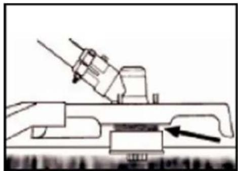
natural_image
Technical line drawing of a mechanical assembly with a tool and base component (no text or symbols)natural_image
Diagram of a mechanical device emitting smoke or vapor, with arrows indicating direction (no text or symbols)CORTANDO ALREDEDOR DE LOS ÁRBOLES
natural_image
Close-up of hands holding a small black object with a white tool, possibly a tool or device (no visible text or symbols)
natural_image
Close-up of hands holding a black mechanical component (no visible text or symbols)natural_image
Close-up of a hand holding a mechanical component with wires, no visible text or symbols
natural_image
Close-up of hands holding a black cylindrical object (no visible text or symbols)natural_image
Technical line drawing of a mechanical assembly with no visible text or symbolsnatural_image
Close-up of a black and orange FUKTEC device with a hand adjusting its button (no visible text or symbols on the device itself)
natural_image
Close-up of a black industrial device with orange and black components, no visible text or symbols
natural_image
Close-up of a black plastic enclosure with a circular dial and a rectangular cover (no visible text or symbols)text_image
0.6~0.7mm OSATENCIÓN