
FSM-ART-M-EFS - Wall mount MONSTER - Free user manual and instructions
Find the device manual for free FSM-ART-M-EFS MONSTER in PDF.

| Product Type | Articulated wall mount with surge protection and built-in Clean Power filtering |
| Brand | Monster |
| Model | FSM-ART-M-EFS |
| Screen Compatibility | 27 to 46 inches |
| Maximum Supported Weight | 100 lb (45.4 kg) |
| Dimensions (Width) | 150 mm |
| Power Supply | 120 V / 60 Hz, 15 A, 1800 W |
| Total Energy Dissipation | 4320 Joules |
| Surge Protection | Yes, SurgeGuard with 4320 J absorption |
| Electrical Filtering | HD Clean Power Stage 1 Noise Filtration |
| Arm Type | Extendable articulated Z-Fold arms with 3 hinges |
| Rotation | 180° left/right |
| FlexTilt Tilt | 20° forward, 5° backward |
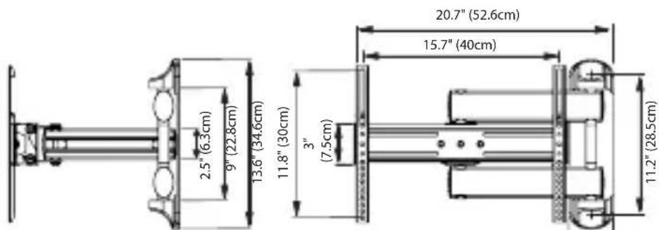
| Maximum Extension | 24 in (61 cm) from wall |
| Cable Management | Yes, with built-in cable pass-throughs and covers |
| VESA Standard | Adapter included for VESA up to 400 x 400 mm |
| Installation | On wood studs or masonry (brick, solid concrete, concrete blocks) |
| Required Tools | Drill, drill bits (3/16 in for wood, 1/2 in for masonry), level, stud finder |
| Product Warranty | Lifetime warranty (valid for original purchaser) |
| Connected Equipment Warranty | 5 years, up to $50,000 US |
| Country of Manufacture | China |
| Maintenance and Cleaning | Unplug the unit, dust with a dry cloth; do not use liquid cleaners |
| Safety Instructions | Do not install on sloping surface, do not use without grounding, do not expose to water or excessive heat |
| Package Contents | Mounting system, power supply bracket, power supply, power supply mounting plate, screw caps, end caps, washers |
Frequently Asked Questions - FSM-ART-M-EFS MONSTER
User questions about FSM-ART-M-EFS MONSTER
0 question about this device. Answer the ones you know or ask your own.
Ask a new question about this device
Download the instructions for your Wall mount in PDF format for free! Find your manual FSM-ART-M-EFS - MONSTER and take your electronic device back in hand. On this page are published all the documents necessary for the use of your device. FSM-ART-M-EFS by MONSTER.
USER MANUAL FSM-ART-M-EFS MONSTER
with Power Protection
Medium Articulating Mount

THANK YOU for purchasing
a Monster Flatscreen™ Articulating Mount with built-in power protection against surges and Clean Power® filtering. This mount reflects our passion for creating the most innovative and practical AV solutions on the market to enhance your viewing experience.
The built-in PowerCenter features patented HD Clean Power that
rejects electrical interference to maximize your flatscreen TV's performance. It also provides a high level of power protection to keep your TV safe from dangerous surges and spikes.
Monster Flatscreen Articulating Mounts are safe, secure, and easy to install. Extending swing arms and an all-directional pivot joint provide almost infinite viewing possibilities. Start enjoying TV on your terms—when, where and how you want to watch.

Noel Lee,
The Head Monster

natural_image
Portrait of a smiling man wearing glasses and a dark shirt (no text or symbols visible)More Great Products from Monster FlatScreen™
Get the Look You Want and the Performance You Need.
Monster FlatScreen CleanView™ Cable Manager
Conceal unruly cords and cables for a clean, sleek look. Easy to install with paintable covers to match any décor.

natural_image
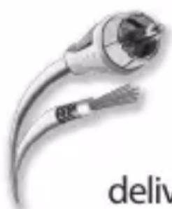
Close-up of a metallic electrical plug with coiled cable (no text or symbols visible)Monster FlatScreen Cables™
Monster Flatscreen Cables are compact and flexible for easy routing and installation. Exclusive Monster patented technologies deliver the advanced performance you need from your flatscreen TV.
Monster FlatScreen PowerProtect™ and PowerCenters™
Protect your flatscreen TV from harmful surges and spikes and maximize performance with Monster Tri-Mode ^® surge protection and HD Clean Power ^® filtering, designed specifically for HDTVs.

natural_image
Black industrial device with control panel and indicator lights (no visible text or symbols)
natural_image
Close-up of a cleaning tool on a textured surface (no visible text or symbols)Monster FlatScreen Clean™
Safely clean your LCD or plasma flatscreen TV without staining, streaking, or dripping. Ultra-soft MicroFiber cloth won't scratch delicate screen coatings.
For more details on all our Monster FlatScreen products, visit us at MonsterCable.com/FlatScreen
MONSTER FLATSCREE MOUNTS
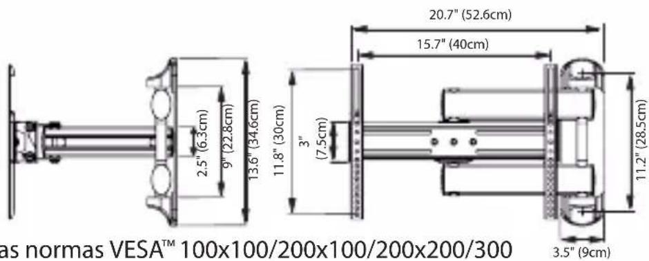
Medium Articulating FlatScreen Mount
This mount is designed to mount 27"-to-46" flatscreen televisions to vertical walls. Maximum weight capacity is 100 lbs.
SAFETY WARNING: If you don't understand these directions, or have doubts about this product's installation, please call a qualified contractor or contact Monster Cable Products, Inc.
U.S. and Mexico customers: call 1-877-800-8989
Canada customers: call 1-866-348-4171
Before installing, carefully review the instructions to ensure that no parts are missing or defective. Improper installation can cause damage or serious injury. Do not use this product for any purpose not explicitly specified by Monster. Monster is not liable for damage or injury caused by incorrect assembly, incorrect mounting or incorrect use.
All hardware is supplied for the following wall conditions: Wood stud, brick, solid concrete, and concrete block.
Note: The supplied hardware is not for steel stud walls. If you are uncertain about the nature of your wall construction, consult an installation contractor.

Patented HD Clean Power® Removes Noise and Interference
Your home's electricity is full of noise and interference caused by all of your appliances and electronics: cell phones, computers, even your lights, all contribute to the problem. This “dirty power” stresses the delicate digital circuitry inside flatscreen TVs and other home theater equipment, reducing their performance and potentially shortening their lives.
Patented Monster HD Clean Power® filtering is precision-engineered to remove electrical noise and interference. HD Clean Power protects your valuable flatscreen TV and ensures the best picture and sound performance.

Protect Your Valuable Flatscreen TV
Common power surges and spikes can easily damage your valuable flatscreen TV. Monster SurgeGuard™ provides 4320 Joules of protection to keep your equipment safe from dangerous power conditions. Additionally, the PowerCenter™ includes surge-protected coax connections to protect against surges on cable, satellite, and antenna lines.
Specifications and Notes:
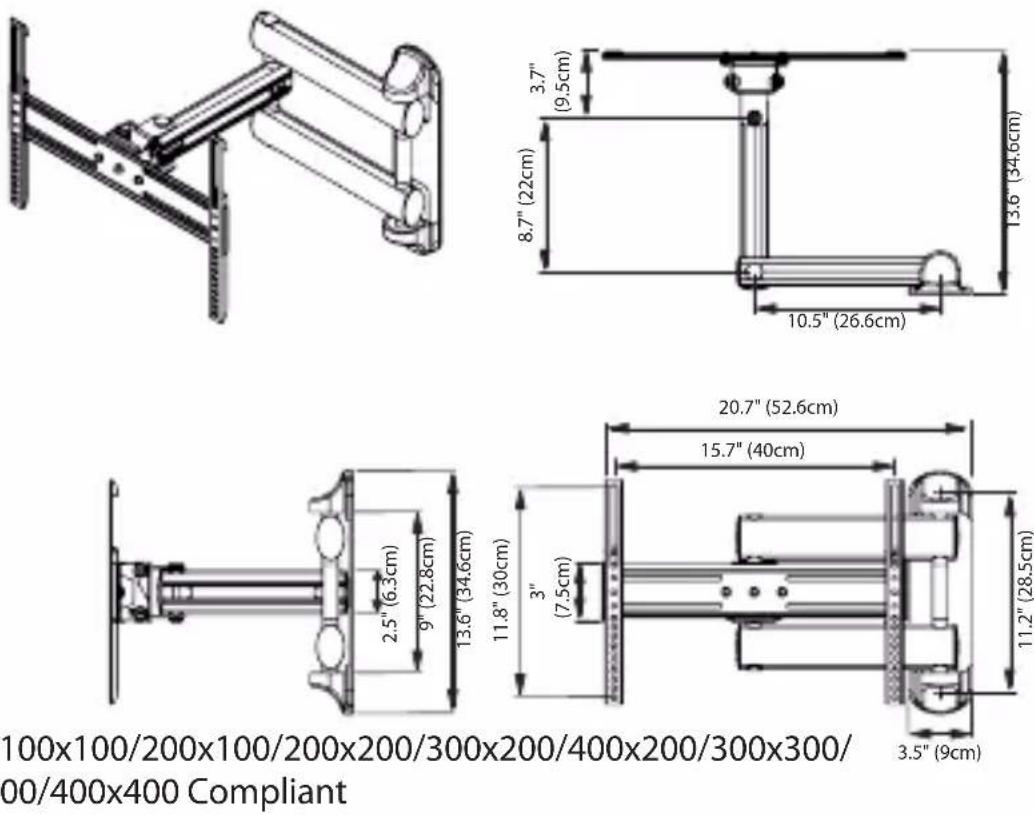
VESA™ 100x100/200x100/200x200/300x200/400x200/300x300/400x300/400x400 Compliant
Monster is constantly striving to improve its products. Specifications are subject to change without notice.
Required Tools
Wood Stud Mounting:
Electronic stud sensor•
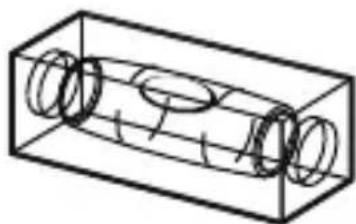
Level (included)•
Electric hand drill•
3/16" drill bit•
Phillips screwdriver•
Combination wrenches or socket set•
Masonry Mounting
(brick, solid concrete, concrete blocks):
Above tools, plus hammer•
Replace 3/16" drill bit with 1/2" masonry drill bit•
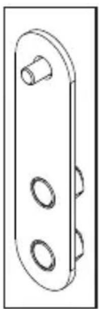
Adapter Included for VESA™ 400x400 Pattern:
natural_image
Technical line drawing of a mechanical bracket with three circular cutouts (no text or symbols)VESA is an international organization that sets industry-wide standards for consumer electronics. VESA information referred to in this manual describes the patterns of holes in the back of your TV and how they match to specific Monster Flatscreen™ mounts.
Four extension adapters are included to extend the mount's VESA compliant standard to 400x 400mm. If your TV's VESA pattern requires this adapter, refer to pages 14-15 for instructions.
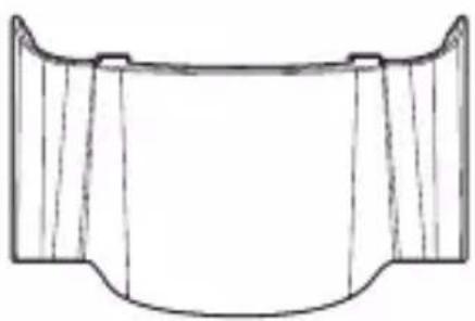
Package Contents
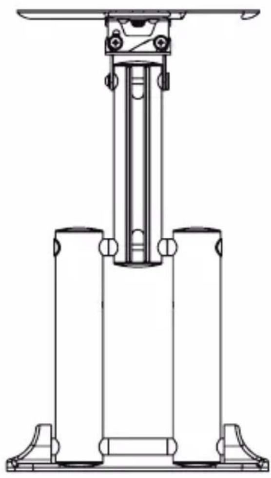
natural_image
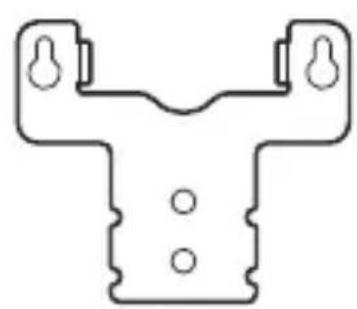
Technical line drawing of a mechanical device with three vertical supports and mounting feet (no text or symbols)1 Mounting System
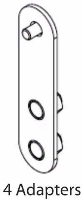
natural_image
Technical line drawing of a 4-adapted mechanical component with three circular holes (no text or symbols)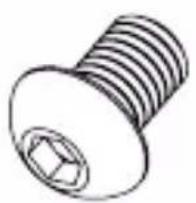
natural_image
Simple line drawing of a bolt with threaded shaft and hexagonal nut (no text or symbols)4 Allen Head Screws
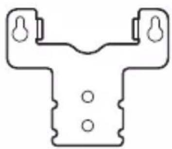
natural_image
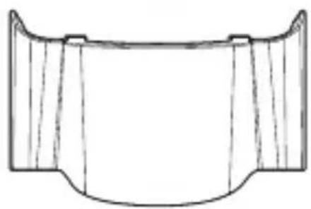
Pure mechanical component outline without any text, numbers, or symbols1 Power Unit Mounting Bracket
natural_image
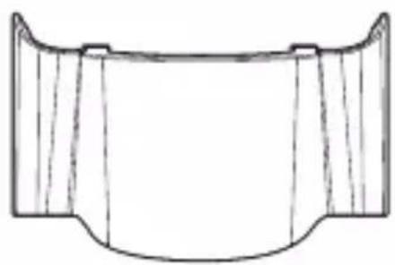
Technical line drawing of a mechanical component with symmetrical sections (no text or symbols)1 Quick Snap Screw Cap
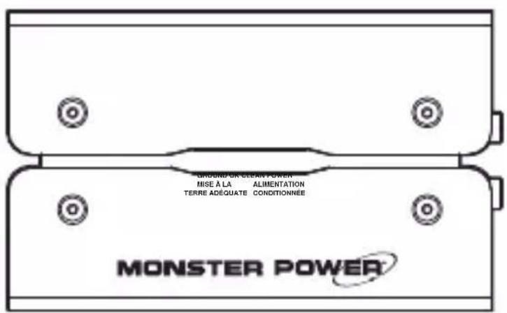
1 Power Unit
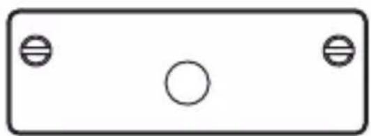
natural_image
Simple diagram of a rectangular frame with two circular holes at the top and bottom (no text or symbols)1 Power Unit Mounting Plate
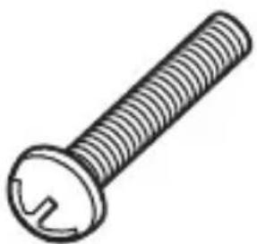
natural_image
Line drawing of a standard bolt with threaded shaft and circular head (no text or symbols)Phillips Screws
4 ea. M4x12 A
4 ea. M4x25 B
4 ea. M4x40
4 ea. M5x12
4 ea. M5x25
4 ea. M5x40
4 ea. M6x12
4 ea. M6x25
4 ea. M6x40

natural_image
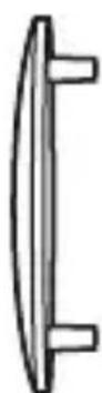
Line drawing of a mechanical component with two views (top and side), no text or symbols present.2 Quick-Snap Screw Caps

natural_image
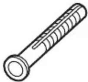
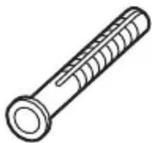
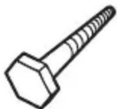
Simple line drawing of a hexagonal bolt with threaded shaft (no text or symbols)2 Lag Bolts

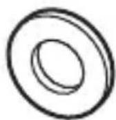
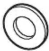
2 Round Washers

natural_image
Line drawing of a threaded bolt (no text or symbols)2 Concrete Anchors
natural_image
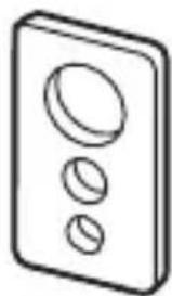
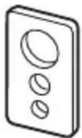
Simple line drawing of a three-hole electrical switch (no text or symbols)4 Square Washers
natural_image
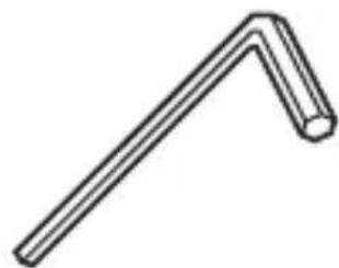
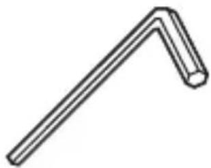
Simple line drawing of a right-angle pipe fitting (no text or symbols)2 Allen Wrenches

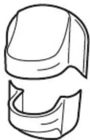
5 End Caps

natural_image
Isometric line drawing of a rectangular container with three cylindrical rings inside (no text or symbols)Bubble Level
IMPORTANT SAFETY INFORMATION for PowerMount Wall Unit
Please read and observe the following safety points at all times.

WARNING – Power Sources
DO NOT plug the mounting system power unit into a power outlet that differs from the source indicated for safe use on the unit. If you don't know the type of electrical power that is supplied to your home, consult your local power company or a qualified electrician.

WARNING – Grounding and Polarization
A. DO NOT force the power unit's plug into an outlet that is not designed to accept grounded AC plugs. This plug is designed to be inserted into a grounded-type outlet only. If the plug doesn't fit directly into your outlet, do not attempt to force it into the outlet. Never attempt to dismantle the plug in any way (or to alter the power cord). If you have questions about grounding, consult your local power company or a qualified electrician.
B. If you use rooftop devices such as satellite dishes, antennae or any other component with wire that connects to your power unit, be sure the wire(s) is properly grounded. This protects against voltage surges and static charges.
C. DO NOT place any antenna near overhead power lines or any other power circuit. DO NOT touch any power line or power circuit. Doing so may cause severe physical injury or possibly death.

WARNING – Liquid, Avoiding Electrical Shocks
A. DO NOT operate the power unit if liquid of any kind is spilled on it or inside it.
B. DO NOT operate the power unit near rain or water that's spilled or contained (e.g., bathtub, kitchen or sink).

WARNING – Power Cord Safety
A. When routing the power unit's AC power cord, do not place it near heavy foot traffic (e.g., hallways, doorways and floors). Do not create a trip hazard with the power cord.
B. If the protective jacket on the power unit begins to rip or fray, exposing the internal wiring, shielding, etc., disconnect it from the power source and discontinue use immediately. See the Warranty Information section of this owner's manual for important details.

WARNING – Storm Precautions
In the event of a lightning storm, it's always a good idea to disconnect the power unit; there is no need to disconnect your separate components.
WARNING – No User Serviceable Parts Inside If, for any reason, the power unit is not operating properly, DO NOT remove any part of the unit (cover, etc.) for repair. Unplug the unit and consult the Warranty Information section of this owner's manual for important details.
CAUTION – Exposure to Heat
Do not expose your power unit to direct sunlight or place it near wall heaters, space heaters or any enclosed space prone to temperature increases.
CAUTION – Proper Cleaning
In general, the only cleaning necessary for the power unit is a light dusting. Unplug the unit from the wall before cleaning it. Do not use any type of liquid or aerosol cleaner.
PROPER GROUNDING AND INSTALLATION for PowerMount Wall Unit

WARNING – Proper Grounding
The power unit requires a properly grounded outlet for safety and to protect connected equipment. If you're not sure if your home's electrical wiring is properly grounded, have it checked by a qualified electrician.
IMPORTANT NOTE – Proper Power and Protection
To completely protect your equipment against electrical surges, every AC power cable, coaxial cable, phone line, and Ethernet line in the system must be connected to the power unit or another surge protection unit.
IMPORTANT NOTE – Proper Protection and the Limited Connected Equipment Warranty
The five year, \$50,000 Limited Connected Equipment Warranty becomes invalid if any wire (AC or coax) leading into the equipment comes from a component that is not properly protected by the mounting system power unit. See the Warranty Information section of this owner's manual for important details.
Important: Read Before Installing
WARNING:
DO NOT install on a sloping surface. Install exclusively on a vertical surface.
DO NOT mount to cabinetry made of particleboard.
DO NOT install in a room with excessively high temperatures or high humidity. Install at least 3 ft. from all water sources.
DO NOT install near an air conditioner.
DO NOT install in a location where there is excessive dust, smoke or moisture. These sources can create a fire.
DO NOT apply unnecessary stress or load on the installed unit. Never hang on the unit.
DO NOT install the unit alone. Safe installation requires at least two people.
DO NOT route your flatscreen TV's power cord in wall. Check local building/electrical codes for more information.
CAUTION:
To prevent eye fatigue, DO NOT install where there is direct sunlight or excessive light.
When carrying out maintenance, disconnect the TV's power supply to avoid electrical shock.
⚠️ If planning to route AV cable in wall, only use cable UL-certified for this use.
Pre-Installation Checklist
☐ Your mounting location must have at least one wall stud.
☐ Your view of the mounting location must be free of glare or other obstructions.
□ Your mounting location must be near an AC power outlet. Ideally the outlet should be behind your TV. This allows you to conceal your display's power cord.
☐ Your mounting location must be at least 3 ft. from any source of heat or water
TIP To hide your TV's power cord and AV cables install a Monster FlatScreen™ CleanView™ Cable Manager.
Installing the FlatScreen Mount
Choose a mounting location with convenient access to an AC power outlet.
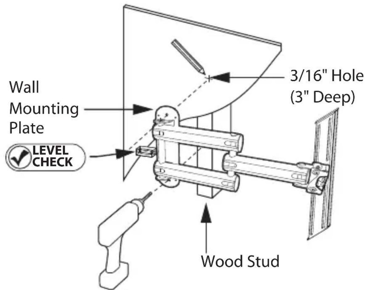
Wood Stud Mounting:
Using an electronic stud sensor, locate a wall stud 1) at your desired mounting location.
2) With the help of a friend, position the wall plate over wall stud. Using the provided level, confirm that the wall plate is vertically straight.
For best results, position the level horizontally with the narrow end flush against the side of the wall plate. Hold the plate firmly in place.
Mark the stud center in the top and bottom mounting 3) holes with a pencil.
With your electrical drill and 3/16" bit, pre-drill a 3" 4) deep hole at each mark.
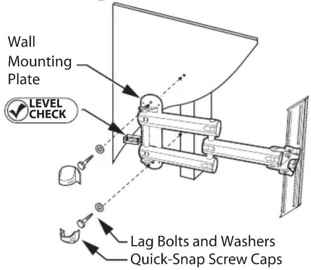
Attach the wall plate to the wall using the supplied 5) lag bolts and round washers, as shown to the right. Tighten each bolt with your electric drill or socket wrench. Turn clockwise until secure.
Attach the wall plate's Quick-Snap Screw Caps 6) to conceal the installed lag bolts.
⚠️ DO NOT over tighten bolts. This can damage the wall plate or the surface of your wall.
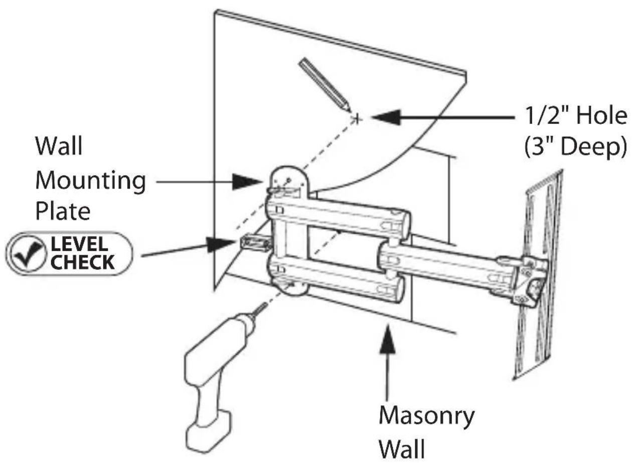
Installing the FlatScreen Mount continued Masonry Mounting
Masonry mounting requires specialized knowledge, skills and tools. Monster highly recommends that you seek the help of a professional installer when mounting to masonry.
With the help of a friend, position the mounting plate 1) in your desired mounting location.
2) VSHACK the provided level, confirm that the wall plate is vertically straight. Position the level horizontally with the narrow end flush against the side of the wall plate. Hold the plate firmly in place.
Mark the centers of the top and bottom mounting 3) holes on the wall plate with a pencil. Be careful not to mark a mortar joint. With your electrical drill and 1/2" masonry bit, pre-drill a 3" deep hole at each mark.
Install the supplied plastic anchors in each hole. 4) Tap into hole until fully seated.
Attach the wall plate to the wall using the supplied 5) lag bolts and round washers, as shown to the right.
Attach the wall plate's Quick-Snap Screw Caps 6) to conceal the installed lag bolts.
⚠️ DO NOT over tighten bolts. This can damage the wall plate or the surface of your wall.
⚠️ DO NOT release the wall plate until you are absolutely sure it is secured to the wall.

Attaching the Power Unit to the Installed Mount
Insert the power unit mounting bracket in the 1) square-shaped slot on the back of the power unit, as shown to the right.
2ecure the power unit mounting bracket to the power unit with two Phillips screws, labeled "A" on the hardware bag.
Hang the power unit mounting bracket on the two rivets 3) protruding from the power unit mounting plate.
Pull the power unit downward to safely secure it on the 4) power unit mounting plate.
Slide the Quick-Snap screw cap into place over the power 5) unit mounting plate screw holes.
Power Unit
Mounting Bracket
Phillips Screws
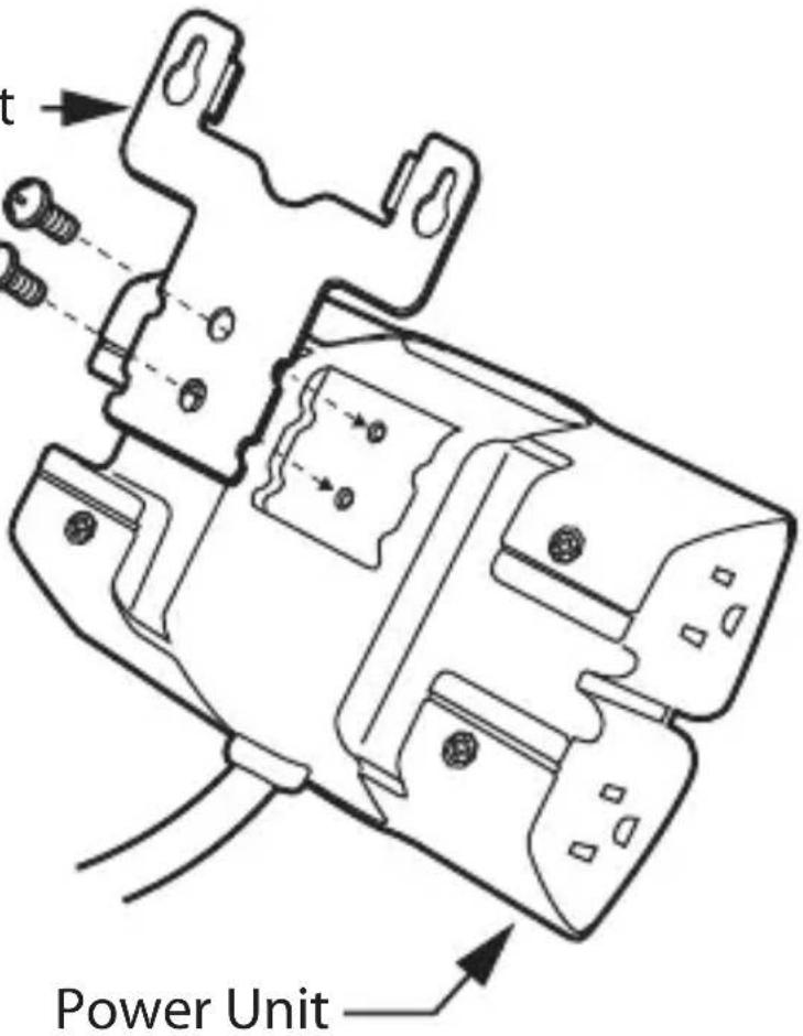
Quick-Snap Screw Cap -

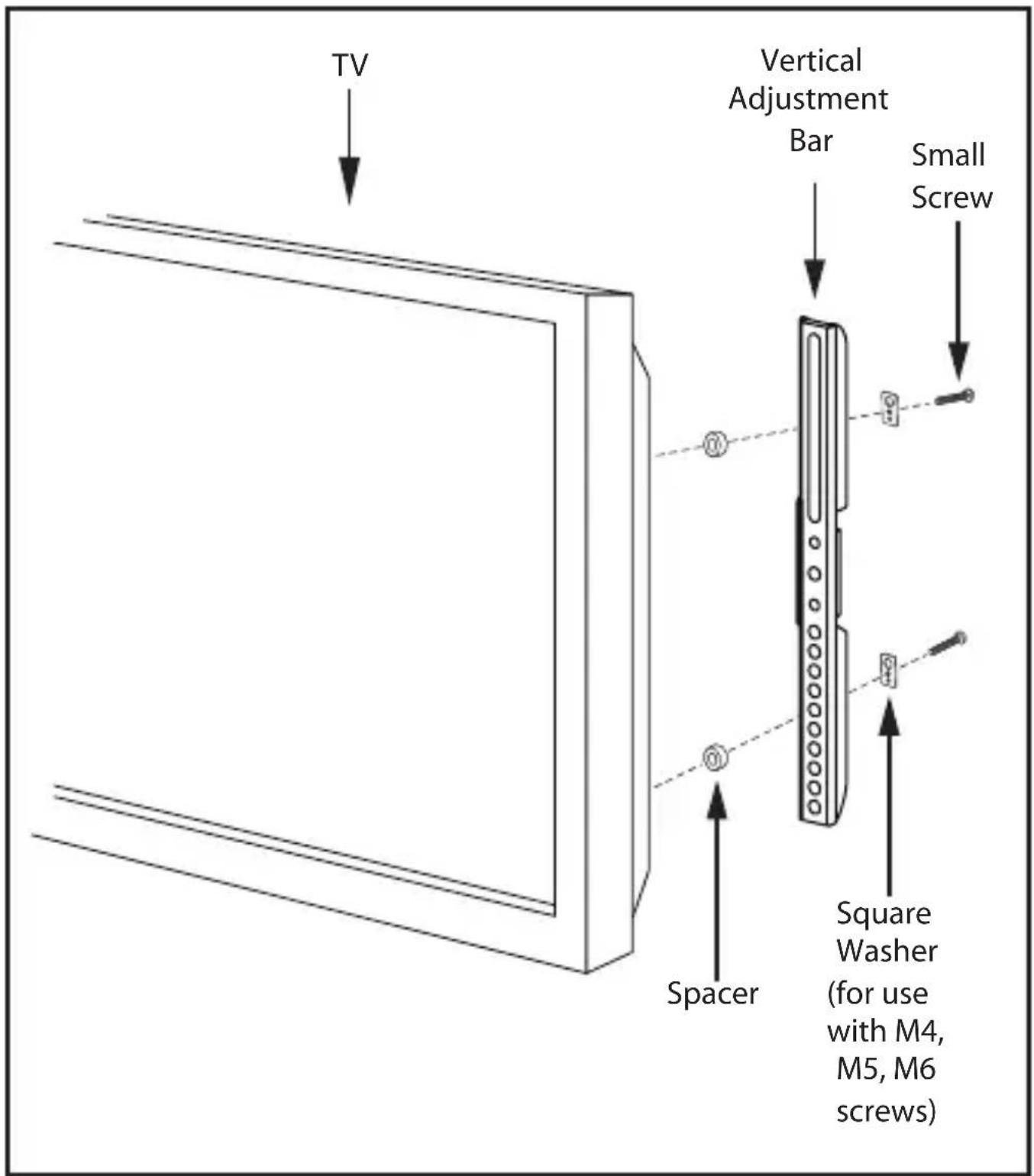
Attaching the Vertical Adjustment Bars to the TV

DO NOT lay your TV face down when attaching the Vertical Adjustment Bars. This can cause permanent damage to your screen. Lean it against a wall or other solid surface so it remains vertically upright.

The television should be unplugged before threading any bolt or screw into the back panel.
Your mounting system features 12 sets of screws of varying diameter and length. Before attaching the adjustment bars to your display, determine which screw set is correct for your display.
TVs with flat backs use a shorter screw without a spacer. TVs with curved backs or recessed inserts may require a longer screw with a spacer between the TV and adjustment bars. Smaller M4, M5 or M6 screws require a square washer (supplied) between the adjustment bar and each screw.
Locate the threaded inserts on your TV's back panel. 1) Thread a screw from the set into one of the inserts to ensure it is the correct choice.
Thread screws through the adjustment bars into the 2) TV inserts with the appropriate spacer and washer set, if needed.
With a Phillips screwdriver, tighten the screws so the 3) adjustment bars are firmly attached to the TV.
⚠️ DO NOT over tighten screws. Thread screws carefully by hand before tightening. If you feel any resistance, remove the screw immediately.
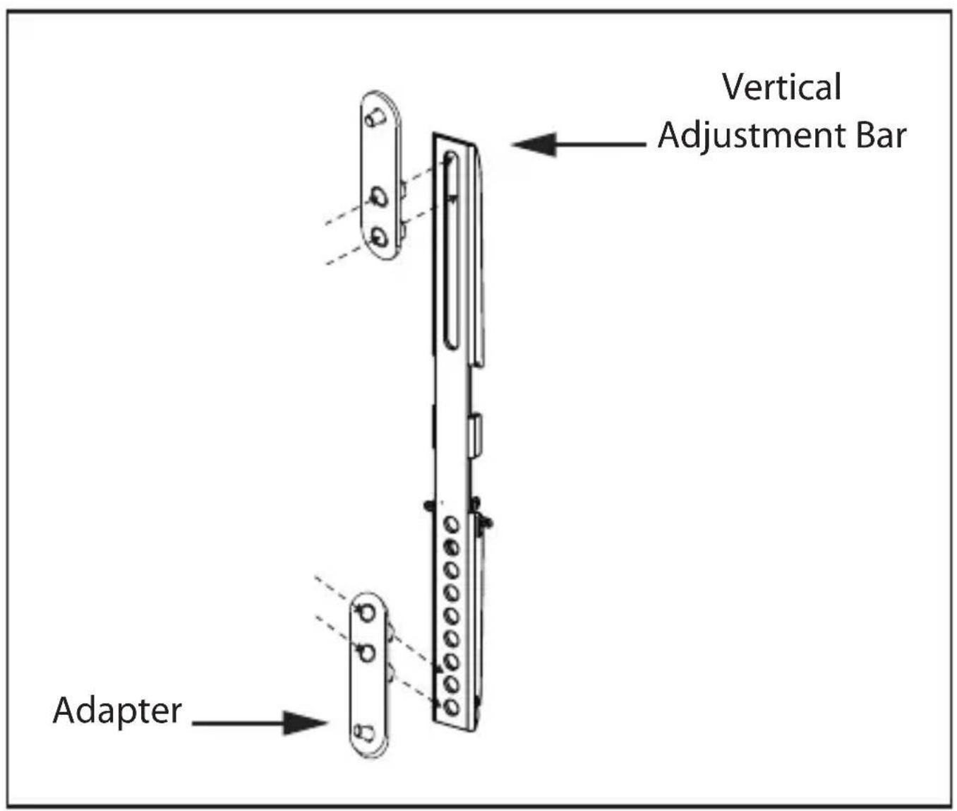
Attaching Extension Adapters to Extend VESA™ Pattern to 400x400
NOTE: Each adapter includes two threaded studs and nuts. No additional hardware is required to attach the adapter to the mount.
To attach the adapter to the ends of Vertical 1) Adjustment Bars, place the adapter in front of the Vertical Adjustment Bar. The adapter should be attached at the uppermost slot at the top of each Vertical Adjustment Bar and the lowest two holes in the bottom of each Vertical Adjustment Bar.
Using a 12 " (13mm) wrench, attach the adapter 2) by tightening the two nuts through the back of the Vertical Adjustment Bar.
Using a Phillips head screwdriver, affix the adapter's 3) head cap screws to the back of your TV
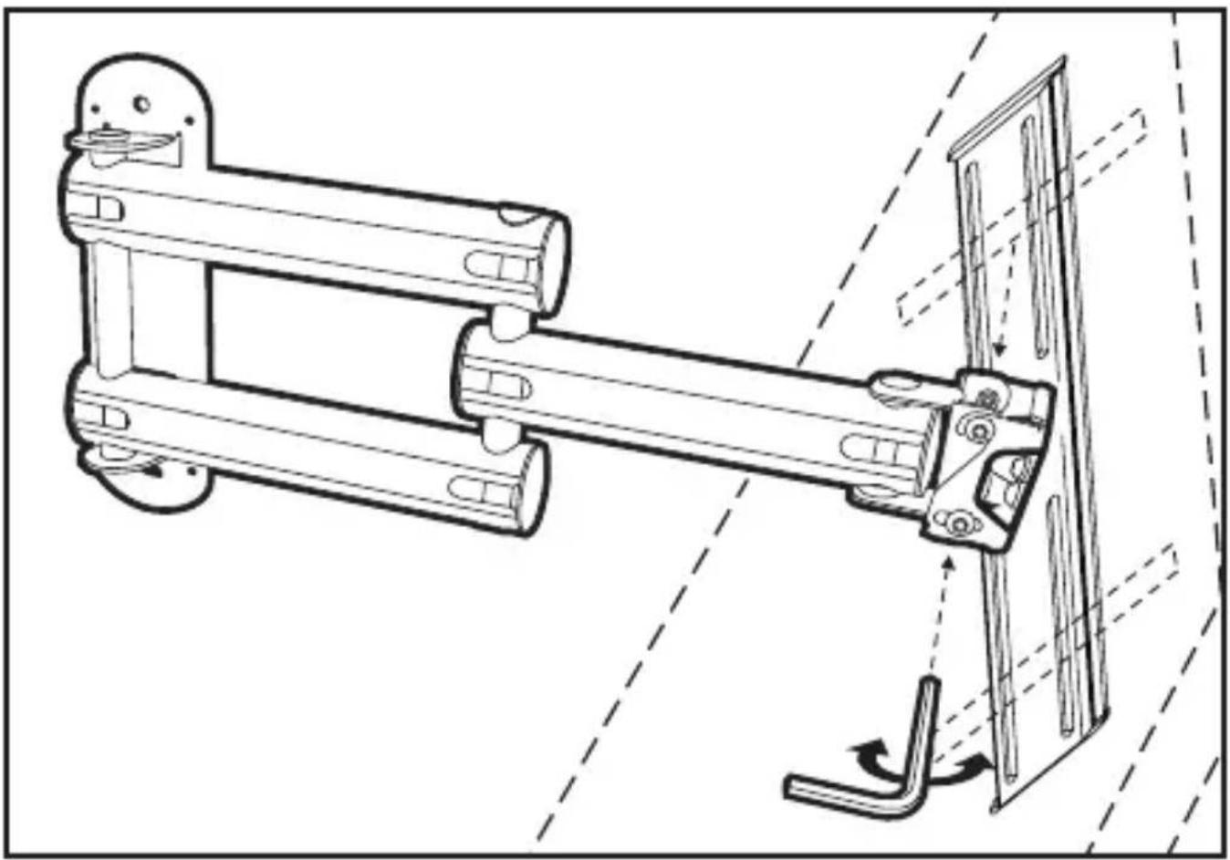
Hanging the TV and Vertical Adjustment Bars on the Wall Plate

Monster strongly recommends that a minimum of two people perform the following steps.

DO NOT release the TV until you are certain it is properly mounted and secured to the wall plate.
With the mount securely attached to the wall, extend 1) the Z-Fold™ swing arms away from the wall.
2) Locate the QuickLift™ hooks on the back of the Vertical Adjustment Bars, now attached to your TV.
3) Hang the QuickLift hooks on the TV mounting plate's top and bottom horizontal channels.
Secure the Vertical Adjustment Bars to the mounting 4) plate by threading the four Allen head screws through the back of the mounting plate and through the vertical adjustment bars. Tighten screws with supplied Allen wrench.

Adjusting the Flexibility of the Z-Fold™ Extending Swing Arms
This mount features heavy-duty Z-Fold Extending Swing Arms with three independent arm hinges.
- The Z-Fold swing arms extend your display up to 24" from the wall.
All three arm hinges swivel your TV left or right 180.°*•
Each arm hinge has an adjustable tension screw, adjustable before or after the TV and mounting plate are attached to the swing arms.
Remove the plastic cap on the bottom 1) of any arm hinge, as shown to the right, to access its tension screw.
With an Allen wrench, turn the tension screws 2) counterclockwise to reduce swivel tension.
Turn the screws clockwise to increase swivel tension.3)

natural_image
Technical line drawing of a mechanical assembly with directional arrows indicating motion (no text or symbols)Using the Mount's FlexTilt™ Screen Adjustment System
This mount features a FlexTilt™ screen adjustment system for tilting the top of your TV forward 20° or backward 5.° This reduces glare and enhances your view while seated. Follow the steps below to quickly and easily tilt you screen.
1) Fully extend the mount's Z-Fold swing arms.
Note the lower tension screws on each side 2) of the bracket connecting the Z-Fold swing arms to the TV mounting plate.
With an Allen wrench, turn the tension screws 3) counterclockwise to loosen the bracket and tilt the top of the screen forward or backward.
To lock your display in place at the desired tilt, 4) retighten the tension screws, turning them clockwise.
natural_image
Technical line drawing of a mechanical assembly with no visible text or symbolsLeveling the TV

DO NOT over-loosen the tension screws on the back of the TV mounting plate. The mounting plate and TV could fall off the mount.
Note the three tension screws on the back 1) of the TV mounting plate as shown.
Turn the left and right tension screws counterclockwise 2) to initiate screen leveling.
If rotation is still limited after loosening the left 3) and right screws, loosen the center tension screw.
4) By hand, rotate the screen left or right.
In the desired position, use the supplied level to ensure the screen is completely horizontal.
Retighten the tension screws, turning them clockwise.

natural_image
Technical diagram of a mechanical assembly with motion indicators and component placement (no text or symbols)Routing Your TV's Power Cord and AV Cable through the Cable Management System
With the mount completely installed on the wall 1) and your TV properly secured to the mount, fully extend the mount's Z-Fold™ swing arms.
Swing the mount completely to the left or right. 2) This enables you to slide off the cable channel covers on all three swing arms.
Connect your TV's power cord to the TV (if TV uses 3) a detachable-type power cord).
Slide the cable channel covers off the swing arms, 4) as shown to the right.
Route your TV's power cord through the bottom 5) cable channel.
Route AV cable from your wall, set-top box, AV receiver, 6) or other source through the top channel and second arm, as shown to the right and make connections to your TV.
Slide the cable channel covers back into place. 7) Snap the swing arm end caps back on, as shown.
Plug the TV power cord into one of the power unit's 8) AC outlets.
Plug the Power Unit's attached 8ft. power cord into 9) a nearby AC wall outlet.
LED indicators on the Power Unit should illuminate.10)
"Clean Power ON" indicates 11) Clean Powering is active.
"Ground OK" indicates house wiring and/or AC outlet 12 is properly grounded. If not illuminated, unplug Power Unit and consult an electrician.


Congratulations
You've successfully installed your Monster FlatScreen™ Articulating Mount.
Visit www.MonsterCable.com/FlatScreen for more innovative Monster FlatScreen products.Congratulations
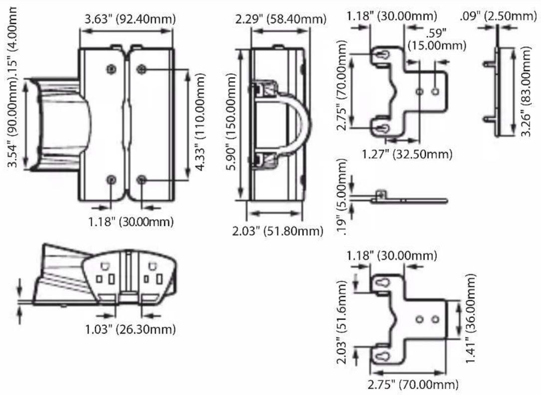
Specifications FlatScreen Mount PowerCenter
| Continuous Duty Electrical Rating 120V/60Hz | |
| Maximum Current Rating | 15A/1800W |
| Protection Mode Line-Neutral (L-N) Line-Ground (L-G) Neutral-Ground (N-G) | |
| Total Energy Dissipation 4320 Joules | |
| Dimensions Width: 5.91" 150 mm | |
| Height: 3.62" 92 mm | |
| Depth: 2.05" 52 mm | |
LIMITED WARRANTY FOR CONSUMERS
Monster, LLC, 7251 Lake Mead Blvd West, Las Vegas, NV 89128, USA ("Monster") extends to You this Limited Warranty. Statutory or common law may provide You with additional rights or remedies, which shall not be affected by this Limited Warranty.
DEFINITIONS
"Adequate Use" means use of the Product and Connected Equipment (i) within a home or dwelling, (ii) for private (as opposed to commercial) purposes, (iii) in conformance with all applicable local, state or federal law, code or regulations (including without limitation building and/or electrical codes), (iv) in accordance with manufacturer recommendations and/or instructions in the materials and documentation that accompany the Product and any Connected Equipment, (v) with proper electrical grounding, (vi) with proper and direct connection between the Product and an AC power source that has protective grounding (excluding gas or diesel powered generators), (vii) with cable or telephone lines to any Connected Equipment properly connected to the Product, and (viii) without a connection in a "daisy-chain" fashion to or with any extension cord, surge suppressor, power strip, uninterruptible power supply ("UPS") or other equipment.
"Authorized Dealer" means any distributor, reseller or retailer that (i) was duly authorized to do business in the jurisdiction where it sold the Product to You, (ii) was permitted to sell You the Product under the laws of the jurisdiction where You bought the Product, and (iii) sold You the Product new and in its original packaging.
"Connected Equipment" means any device that is (i) generally suited to be used with the Product or products of the same kind, (ii) meets the requirements of all applicable laws and safety standards, (iii) contains only parts manufactured, sold or recommended by the original manufacturer of the Connected Equipment, and (iv) has not been altered, tampered with or modified by any person other than its manufacturer or service personnel authorized or recommended by the manufacturer of the Connected Equipment.
"Connected Equipment Damage" means physical damage to Connected Equipment caused by a Product Defect by a transient AC power, cable, telephone, or lightning surge while connected to a properly installed Product. Connected Equipment Damage (i) may not be caused by a defect or unrelated damaging of the Connected Equipment or a surge/spike or lightning strike through a source, medium or connection other than through the Product, and (ii) does not extend to loss of data, or consequential, indirect or special damages resulting from the Connected Equipment Damage.
"Fair Market Value" ("FMV") means the fair market value of the Connected Equipment at the time Connected Equipment Damage occurs..
"Formal Warranty Claim" means a claim made in accordance with the section "Formal Warranty Claims" herein.
"Maximum Coverage Amount" means the maximum amount that Monster will pay to You under this Limited Warranty for Connected Equipment Damages and is defined in relation to each Product in the Specifications Table below.
"Product" means a Product (i) that is listed in the Specifications Table below, (ii) that You bought from an Authorized Dealer new and in its original packaging, and (iii) whose serial number, if any, has not been removed, altered, or defaced.
"Product Defect" means a defect, malfunction, non-conformance to this Limited Warranty or other inadequacy of the Product that existed at the time when You received the Product from an Authorized Dealer and that causes a failure of the Product to perform in accordance with Monster's documentation accompanying the Product, unless such failure has been caused completely or partly by (a) any use other than Adequate Use, (b) transportation, neglect, misuse or abuse by anyone other than Monster's employees; (c) alteration, tampering or modification of the product by anyone other than a Monster employee; (d) accident (other than a malfunction that would otherwise qualify as a Product Defect); (e) maintenance or service of the Product by anyone other than a Monster employee; (f) exposure of the Product to heat, bright light, sun, liquids, sand or other contaminants; or (g) acts outside the control of Monster, including without limitation acts of God, fire, storms (excluding lightning surges), earthquake or flood.
"Warranty Period" means the time period during which Monster must have received Your Formal Warranty Claim. The different Warranty Periods related to Product Defects and Connected Equipment Damage are defined in the Specifications Table below. The Warranty Period commences on the date when You purchased or received (whichever occurs later) the Product from an Authorized Dealer as evidenced by the Authorized Dealer's invoice, sales receipt or packing slip. If You do not have written proof of the date of purchase or receipt, then the Warranty Period commences three (3) months after the date when the Product left Monster's factory as evidenced by Monster's records. The Warranty Period ends after the time defined in the Specifications Table has expired, or after You have transferred ownership of the Product, whichever occurs earlier. Also, You must call Monster and obtain a Return Authorization Number (as described under "How to Make a Claim") within two (2) months after You discover a Product Defect (or should have discovered it, if such Product Defect was obvious).
"You" means the first individual person that purchased the Product in its original packaging from an Authorized Dealer. This Limited Warranty does not apply to persons or entities that bought the Product (i) in used or unpackaged form, (ii) for resale, lease or other commercial use, or (iii) from someone other than an Authorized Dealer.
PRODUCTS. If a Product contained a Product Defect when You bought it from an Authorized Dealer and Monster receives a Formal Warranty Claim from You within two (2) months after You discover such Product Defect (or should have discovered it, if such Product Defect was obvious) and before the end of the Warranty Period for Product Defects applicable to the affected Product, then Monster will provide You with one of the following remedies: Monster will (1) repair or, at Monster's sole discretion, replace the Product, or (2) refund to You the purchase price You paid to the Authorized Dealer for the affected Product if repair or replacement is not commercially practicable or cannot be timely made.
CONNECTED EQUIPMENT DAMAGE. Monster will also provide You with a remedy regarding Connected Equipment Damage if (i) You have a claim under the Limited Warranty for Products because of a Product Defect that causes Connected Equipment Damage despite Adequate Use, and (ii) Monster receives a Formal Warranty Claim from You before the end of the Warranty Period for Connected Equipment Damage applicable to the affected Product. If the conditions listed in the preceding sentence are met, Monster will provide You with one of the following remedies provided that Monster may decide at its sole discretion which of the three remedies it provides: Monster will (1) replace the damaged Connected Equipment; (2) pay to repair the damaged Connected Equipment; or (3) pay You the FMV of the Connected Equipment, provided that such payments shall not exceed (i) the Maximum Coverage Amount for the Product, or (ii) the actual damage having arisen from power surges due to a Product Defect. NOTE: COMPENSATION FOR RESTORATION OF DATA LOSS IS NOT COVERED AND MONSTER DOES NOT ASSUME ANY LIABILITY FOR ANY INCIDENTAL, CONSEQUENTIAL OR INDIRECT DAMAGES UNDER THIS LIMITED WARRANTY. SOME STATES DO NOT ALLOW THE EXCLUSION OR LIMITATION OF INCIDENTAL OR CONSEQUENTIAL DAMAGES, SO THE ABOVE LIMITATION OR EXCLUSION MAY NOT APPLY TO YOU.
GENERAL PROVISIONS
CHOICE OF LAW/JURISDICTION. The laws of the State of California, USA, govern this warranty. It gives You specific legal rights, and You may also have other rights that vary from state to state and country to country. This warranty does not affect any additional rights You have under laws in your jurisdiction governing the sale of consumer goods, including, without limitation, national laws implementing EC Directive 44/99/EC.
OTHER RIGHTS. THIS LIMITED WARRANTY GIVES YOU SPECIFIC LEGAL RIGHTS, AND YOU MAY ALSO HAVE OTHER RIGHTS, WHICH VARY FROM STATE TO STATE AND COUNTRY TO COUNTRY. THIS WARRANTY EXTENDS ONLY TO YOU AND CANNOT BE TRANSFERRED OR ASSIGNED. If any provision of this Limited Warranty is unlawful, void or unenforceable, that provision shall be deemed severable and shall not affect any remaining provisions. In case of any inconsistency between the English and other versions of this Limited Warranty, the English version shall prevail.
REGISTRATION. Please register Your Product at www.MonsterCable.com.
Failure to register will not diminish Your warranty rights.
| Product Model | Maximum Coverage Amount | Warranty Period for Product | Warranty Period for Connected Equipment Damage |
| Medium Articulating Mount with built-in Surge Protection and Clean Power® filtering | $50,000 Lifetime 5 years |
"Lifetime" means the lifetime of the original individual purchaser of the Product, or for as long as the original individual purchaser owns the Product, whichever is less in time.
FORMAL WARRANTY CLAIM
HOW TO MAKE A CLAIM. In the event damage has occurred to Products or Connected Equipment, You must follow these instructions: (1) Call Monster within two (2) months after You discover a Product Defect (or should have discovered it, if such Product Defect was obvious); (2) Give a detailed explanation of how the damage occurred; (3) Obtain a Return Authorization Number; (4) Upon receipt of a claim form (which may be sent to You after You filed Your Formal Warranty Claim), fill out the claim form entirely; (5) Return the Products, shipping prepaid by You (to be refunded if You are entitled to a remedy under the Scope of this Limited Warranty), to Monster for verification of damage, along with a copy of Your original sales receipts and proof of purchase (UPC label or packing slip) for such Products, the completed claim form, and printed Return Authorization Number on the outside of the return package (the claim form will include instructions for return).
TELEPHONE NUMBERS. If you bought the product in the United States, Latin America, or Asia Pacific, contact Monster, LLC (455 Valley Drive, Brisbane, CA 94005) at 1 877 800-8989. If you bought the product anywhere else, contact Monster Technology International Ltd., Ballymaley Business Park, Ennis, Co. Clare, Ireland. You can write or use one of the following telephone numbers: Canada 866-348-4171, Ireland 353 65 68 69 354, Belgium 0800-79201, Czech Republic 800-142471, Denmark 8088-2128, Finland 800-112768, France 0800-918201, Germany 0800-1819388, Greece 00800-353-12008, Italy 800971470, Netherlands 0800-0228919, Norway 800-10906, Russia 810-800-20051353, Spain 900-982-909, Sweden 020-792650, United Kingdom 0800-0569520
FURTHER PROCEEDINGS. Monster will determine whether a Product Defect existed and the damage to the Connected Equipment was caused by the Product. You must allow Monster access to the premises and site where the damage occurred and all equipment and property related thereto for Monster inspection by its employees or authorized representatives. Monster may, at its discretion, direct You to obtain a repair
estimate at a service center or, to send the Connected Equipment to Monster for repair. If a repair estimate is required, You will be instructed on how to properly submit the estimate and the resulting invoice to Monster for payment. Any fees for repairs may be negotiated by Monster.
TIMING. If You bring a Formal Warranty Claim and fully comply with all terms and conditions of this Limited Warranty, Monster will use its best efforts to provide You with a remedy within thirty (30) days after receipt of Your Formal Warranty Claim (if You reside in the United States - forty-five (45) days if You reside elsewhere), unless obstacles outside Monster's control delay the process.
Vers 6-9-09 – GLOBAL ©2003–2009 Monster, LLC
NOTE DE LA DIRECTION DE MONSTER
natural_image
Portrait of a smiling man wearing glasses and a dark shirt (no text or symbols visible)Noel Lee,
Le Monster en chef
natural_image
Close-up of a metallic electrical plug with visible internal wires (no text or symbols)Monster FlatScreen Cables ^MC
natural_image
Black electronic device with visible ports and branding (no readable text or symbols)
natural_image
Close-up of a cleaning tool on a textured surface (no visible text or symbols)Monster FlatScreen Clean MC

VESA™ 100x100/200x100/200x200/300x200/400x200/300x300/400x300/400x400 Compliant
natural_image
Technical line drawing of a mechanical bracket with three circular cutouts (no text or symbols)natural_image
Technical line drawing of a mechanical device with cylindrical components and a vertical support (no text or symbols)natural_image
Technical line drawing of a mechanical bracket with three circular cutouts (no text or symbols)4 Adaptateurs

natural_image
Pure mechanical component outline without any text, numbers, or symbolsnatural_image
Technical line drawing of a bolt with threaded shaft and hexagonal nut (no text or symbols)4 vis à tête
creuse
natural_image
Technical line drawing of a mechanical component with symmetrical sections (no text or symbols)natural_image
Simple diagram of a rectangular frame with two circular holes at the top and bottom (no text or symbols)natural_image
Simple line drawing of a bolt with threaded shaft and circular head (no text or symbols)Vis cruciformes
4 ch. M4x12
4 ch. M4x25
4 ch. M4x40
4 ch. M5x12
4 ch. M5x25
4 ch. M5x40
4 ch. M6x12
4 ch. M6x25
4 ch. M6x40

natural_image
Line drawing of a mechanical component with two views (top and side), no text or symbols present.natural_image
Simple line drawing of a hexagonal bolt with threaded shaft (no text or symbols)2 Tirefonds J

2 Rondelles K
natural_image
Line drawing of a bolt with threaded shaft (no text or symbols)2 Ancrages de béton
natural_image
Simple line drawing of a three-hole electrical switch (no text or symbols)natural_image
Simple line drawing of a right-angle pipe fitting (no text or symbols)2 Clés hexagonales

natural_image
Isometric line drawing of a rectangular container with three cylindrical rings inside (no text or symbols)Niveau à bulle
natural_image
Technical line drawing of a mechanical assembly with directional arrows indicating motion (no text or symbols)FRANCAIS
natural_image
Technical diagram of a mechanical assembly with motion arrows indicating movement, no text or symbols presentnatural_image
Portrait of a smiling man wearing glasses and a dark shirt (no text or symbols visible)Noel Lee,
El Monster Mayor
natural_image
Close-up of a metallic electrical plug with coiled cable (no text or symbols visible)natural_image
Black industrial electronic device with no visible text or symbols on its bodyLimpiador Monster FlatScreen Clean™

natural_image
Close-up of a glass bottle placed on a textured cloth, next to a rolled paper (no visible text or symbols)natural_image
Technical line drawing of a mechanical assembly with two vertical supports and a horizontal rail (no text or symbols)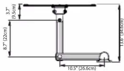
Cumple con las normas VESA™ 100x100/200x100/200x200/300 x200/400x200/300x300/400x300/400x400
natural_image
Technical line drawing of a mechanical bracket with three circular holes (no text or symbols)natural_image
Simple line drawing of a bolt with threaded head and hexagonal end (no text or symbols)natural_image
Pure mechanical component outline without any text, numbers, or symbolsnatural_image
Technical line drawing of a mechanical component with symmetrical sections (no text or symbols)natural_image
Simple diagram of a rectangular frame with two circular holes at the top and center (no text or symbols)natural_image
Line drawing of a standard bolt with threaded shaft and circular head (no text or symbols)Tornillos de cruz
4 pza. M4x12 A
4 pza. M4x25 B
4 pza. M4x40
4 pza. M5x12
4 pza. M5x25 E
4 pza. M5x40
4 pza. M6x12
4 pza. M6x25
4 pza. M6x40
natural_image
Line drawing of a mechanical component with two views (top and side), no text or symbols present.2 tapas Quick-Snap para tornillos
natural_image
Simple line drawing of a hexagonal bolt with threaded shaft (no text or symbols)natural_image
Line drawing of a bolt with threaded shaft (no text or symbols)natural_image
Simple line drawing of a three-tiered electronic device (no text or symbols)natural_image
Simple line drawing of a right-angle pipe fitting (no text or symbols)2 Ilaves Allen
natural_image
Isometric line drawing of a rectangular container with internal cylindrical structures (no text or symbols)Nivel de burbuja
natural_image
Technical line drawing of a mechanical assembly with directional arrows indicating motion (no text or symbols)ESPAÑO!
natural_image
Technical line drawing of a mechanical assembly with no visible text or symbolsnatural_image
Technical diagram of a mechanical assembly with motion indicators and component placement (no text or symbols)Noel Lee,
O Head Monster

natural_image
Portrait of a smiling man wearing glasses and a dark shirt (no text or symbols visible)natural_image
Pure electrical circuit lines without any symbols
natural_image
Close-up of a metallic electrical plug with visible internal wires, labeled 'necess' below (no other text or symbols)Monster FlatScreen Cables™
natural_image
Black industrial device with 'MAYA' branding and '300' label (no readable text beyond branding)
natural_image
Close-up of a cleaning tool on a textured surface (no visible text or symbols)Monster FlatScreen Clean™
natural_image
Technical line drawing of a mechanical assembly with vertical supports and cylindrical components (no text or symbols)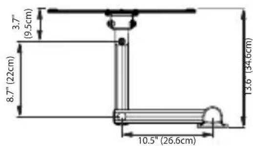
Compatível com VESA™ 100x100/200x100/200x200/300x200/400x200/300x300/400x300/400x400
natural_image
Technical line drawing of a mechanical bracket with three circular cutouts (no text or symbols)natural_image
Technical line drawing of a mechanical device with vertical supports and mounting feet (no text or symbols)natural_image
Technical line drawing of a mechanical bracket with three circular holes (no text or symbols)4 Adaptadores
natural_image
Pure mechanical component outline without any text, numbers, or symbolsnatural_image
Simple line drawing of a bolt with threaded shaft and central screw (no text or symbols)4 Parafusos Allen
natural_image
Technical line drawing of a mechanical component with symmetrical sections (no text or symbols)natural_image
Simple diagram of a rectangular frame with two circular holes at the top and bottom (no text or symbols)natural_image
Line drawing of a standard bolt with threaded shaft and circular head (no text or symbols)Parafusos Phillips
4 de cada M4x12 A
4 de cada M4x25 B
4 de cada M4x40
4 de cada M5x12
4 de cada M5x25
4 de cada M5x40
4 de cada M6x12
4 de cada M6x25
4 de cada M6x40

natural_image
Line drawing of a mechanical component with two views (top and side), no text or symbols present.natural_image
Simple line drawing of a hexagonal bolt with threaded shaft (no text or symbols)2 Parafusos J
natural_image
Line drawing of a bolt with threaded shaft (no text or symbols)natural_image
Simple line drawing of a three-tiered electronic device (no text or symbols)4 Arruelas Quadradas

5 Fechamentos de extremidade
natural_image
Simple line drawing of a right-angle pipe fitting (no text or symbols)2 Chaves Allen

natural_image
Isometric line drawing of a rectangular container with three cylindrical rings inside (no text or symbols)Nível de Bolha
natural_image
Technical line drawing of a mechanical assembly with directional arrows indicating motion (no text or symbols)Usando o Sistema de ajuste de tela FlexTilt™ do Suporte
natural_image
Technical line drawing of a mechanical assembly with no visible text or symbolsNivelando a TV

natural_image
Technical diagram of a mechanical assembly with motion arrows indicating movement, no text or symbols present7251 West Lake Mead Blvd., Las Vegas, NV 89128
Monster Technology International Limited
Ballymaley Business Park Gort Road
Ennis, Co. Clare, Ireland
Engineered in the USA and manufactured for Monster to its quality specifications.
Made in China.
"Monster FlatScreen Mounts," "Monster," "Monster FlatScreen," "Clean Power," "Surgeguard," "Monster FlatScreen Cables," "Monster Power," "Monster FlatScreen Clean," "PowerCenter," "PowerProtect," "Clean Power," "Z-Fold," the Monster logo, "Monster Cable", "CleanView", "TriMode", "FlexTilt", the product and packaging are trademarks or registered trademarks of Monster Cable Products, Inc. or its subsidiaries in the US and other countries. VESA is a trademark of the Video Electronics Standards Association.
- Medium Articulating Mount
- THANK YOU for purchasing
- Noel Lee,
- More Great Products from Monster FlatScreen™
- Monster FlatScreen CleanView™ Cable Manager
- Monster FlatScreen Cables™
- Monster FlatScreen PowerProtect™ and PowerCenters™
- Monster FlatScreen Clean™
- MONSTER FLATSCREE MOUNTS
- Medium Articulating FlatScreen Mount
- Patented HD Clean Power® Removes Noise and Interference
- Protect Your Valuable Flatscreen TV
- Specifications and Notes:
- Required Tools
- Wood Stud Mounting:
- Masonry Mounting
- (brick, solid concrete, concrete blocks):
- Adapter Included for VESA™ 400x400 Pattern:
- Package Contents
- IMPORTANT SAFETY INFORMATION for PowerMount Wall Unit
- WARNING – Power Sources
- WARNING – Grounding and Polarization
- WARNING – Liquid, Avoiding Electrical Shocks
- WARNING – Power Cord Safety
- WARNING – Storm Precautions
- CAUTION – Exposure to Heat
- CAUTION – Proper Cleaning
- PROPER GROUNDING AND INSTALLATION for PowerMount Wall Unit
- WARNING – Proper Grounding
- IMPORTANT NOTE – Proper Power and Protection
- IMPORTANT NOTE – Proper Protection and the Limited Connected Equipment Warranty
- Important: Read Before Installing
- WARNING:
- CAUTION:
- Pre-Installation Checklist
- Installing the FlatScreen Mount
- Choose a mounting location with convenient access to an AC power outlet.
- ⚠️ DO NOT over tighten bolts. This can damage the wall plate or the surface of your wall.
- Installing the FlatScreen Mount continued Masonry Mounting
- Attaching the Power Unit to the Installed Mount
- Attaching the Vertical Adjustment Bars to the TV
- ⚠️ DO NOT over tighten screws. Thread screws carefully by hand before tightening. If you feel any resistance, remove the screw immediately.
- Attaching Extension Adapters to Extend VESA™ Pattern to 400x400
- Hanging the TV and Vertical Adjustment Bars on the Wall Plate
- Adjusting the Flexibility of the Z-Fold™ Extending Swing Arms
- Using the Mount's FlexTilt™ Screen Adjustment System
- Leveling the TV
- Routing Your TV's Power Cord and AV Cable through the Cable Management System
- Congratulations
- LIMITED WARRANTY FOR CONSUMERS
- DEFINITIONS
- GENERAL PROVISIONS
- FORMAL WARRANTY CLAIM
- NOTE DE LA DIRECTION DE MONSTER
- Monster FlatScreen Cables MC
- Monster FlatScreen Clean MC
- Limpiador Monster FlatScreen Clean™
- Usando o Sistema de ajuste de tela FlexTilt™ do Suporte
- Nivelando a TV
Brand : MONSTER
Model : FSM-ART-M-EFS
Category : Wall mount