USER MANUAL HYF013 HONEYWELL
natural_image
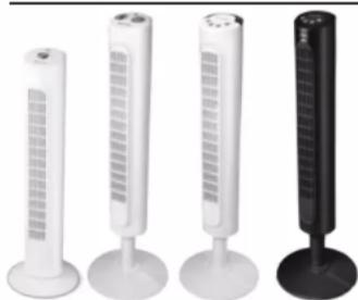
Four different types of white and black electronic devices with ventilation grilles, arranged side by side (no text or symbols visible)
IMPORTANT SAFETY INSTRUCTIONS
READ AND SAVE THESE SAFETY INSTRUCTIONS BEFORE USING THIS FAN
When using electrical appliances, basic precautions should always be followed to reduce the risk of fire, electric shock, and injury to persons, including the following:
FOR US MODELS ONLY – This product employs overload protection (fuse). A blown fuse indicates an overload or short-circuit situation. If the fuse blows, unplug the product from the outlet. Replace the fuse as per the user servicing instructions (follow product marking for proper fuse rating) and check the product. If the replacement fuse blows, a short-circuit may be present and the product should be discarded or returned to an authorized service facility for examination and/or repair.
-
Use this fan only as described in this manual. Other use not recommended as it may cause fire, electric shock or injury to persons.
-
This product is intended for household use ONLY and not for commercial, industrial or outdoor use.
TOWER FAN
Model DYF012 Series
Model HYF013 Series
Model HYF023 Series
-
To protect against electric shock, do not place fan in window, immerse unit, plug or cord in water or spray with liquids.
-
This appliance has a polarized plug (one blade is wider than the other). To reduce the risk of shock, this plug is intended to fit only one way in a polarized outlet. If the plug does not fit fully in the outlet, reverse the plug. If it still does not fit, contact a qualified electrician. Do not attempt to defeat this safety feature.
-
Close supervision is necessary when any appliance is used by or near children.
-
Turn the fan OFF and unplug the fan from the outlet when not in use, when moving the fan from one location to another and before cleaning.
-
To disconnect the fan, first turn the unit OFF, grip the plug and pull it from the wall outlet. Never pull the plug by the cord.
8 Do not operate the fan in the presence of explosive and/or flammable fumes.
-
Do not place the fan or any parts near an open flame, cooking or other heating appliance.
-
Do not operate the fan with a damaged cord or plug or if the product malfunctions, is dropped or damaged in any manner (see warranty).
-
Do not use fan with an extension cord.
-
Avoid contact with moving fan parts.
-
The use of attachments not recommended by the manufacturer may be hazardous.
-
Place the fan on a dry level surface.
-
Do not hang or mount fan on a wall or ceiling.
- Do not operate if the fan housing is damaged.
- A loose fit between the AC outlet (receptacle) and plug may cause over heating and a distortion of the plug. Contact a qualified electrician to replace loose or worn outlet.
- Do not operate any fan with a damaged cord or plug. Discard any damaged fan, return the fan to the retailer where the
fan was purchased, or request a return authorization to return to Kaz USA, Inc. for examination and/or repair.
- Do not run fan cord under carpeting. Do not cover cord with throw rugs, runners, or similar coverings. Do not route cord under furniture or appliances. Arrange cord away from traffic areas and where it will not be tripped over.
WARNING: To Reduce The Risk of Fire or Electric Shock, Do Not Use This Fan With Any Solid-State Speed Control Device.
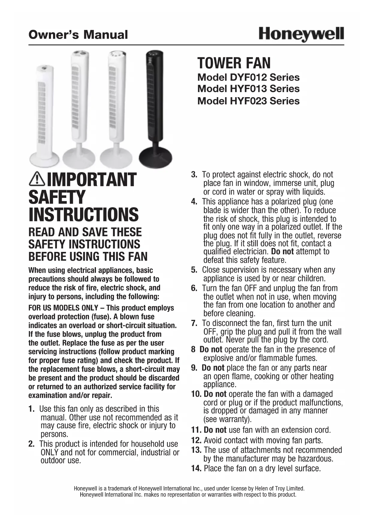
FUSED SAFETY PLUG - FOR US MODELS ONLY
This fan features a fused safety plug which is designed to cut off electric current to the fan if an electrical fault occurs. Please see below for more information on how to properly use your fan and replace the safety plug fuse, if needed.
USER SERVICING INSTRUCTIONS
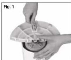
- If your fan loses power and you suspect that the fuse on your fan has blown, grasp plug and remove from the receptacle or other outlet device. Do not unplug by pulling on cord.
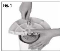
- Slide fuse cover, located on the top of the plug, towards the prongs of the plug. (Fig. 1)
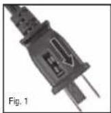
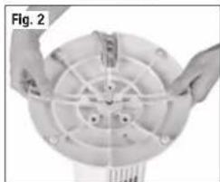
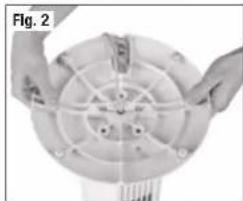
- Carefully remove the blown fuse and snap a new fuse into place. To reduce the risk of fire, replace fuse only with 2.5 Amp, 125 volt fuse. Fully close the fuse door by sliding back into place. (Fig. 2) Discard the blown fuse. The plug should now be ready for normal use.
- To reduce the risk of fire, do not replace attached plug. Contains a safety device (fuse) that should not be removed. Discard product if the attached plug is damaged.
- If you need further information on how or when to replace the fuse in the safety plug, please contact Kaz Consumer Relations Department by visiting our website at www.honeywellpluggedin.com/fans or calling 1-800-477-0457.
DYF012 SERIES ASSEMBLY INSTRUCTIONS
NOTE: Remove all contents from the box being careful not to discard the manual and hardware needed for assembly. A phillips head screw driver (☐) is required for assembly and is not included with the fan purchase.
A. Base Assembly
• Gently turn the fan upside down.
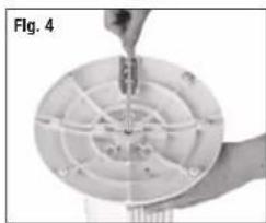
- Place the power cord through the recessed channel located in the center of the rear base assembly (Fig. 1).
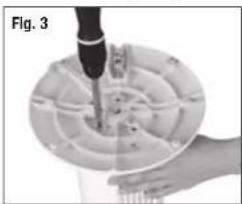
- Align the rear and front base assembly and firmly snap together by pushing the 4 round extrusion into the adjacent circles of the connecting pieces (Fig. 2).
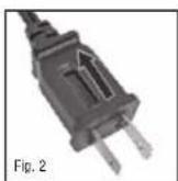
B. Securing the Tower Fan to the Base
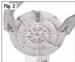
- Using the 3 (M5 x 12) screws and phillips head screw driver (E) secure the base into the bottom portion of the fan housing by aligning the 3 screw holes on the base with the 3 screw holes on the bottom of the fan housing (Fig. 3).
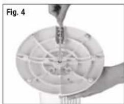
- Gently pull any slack out of the power cord and place the cord securely in the power cord holding bracket (Fig. 4). Fig. 3
- Place the fan right side up. Your fan is now ready for use.
natural_image
Close-up of a hand holding a mechanical component with a tool inserted, labeled 'Fig. 3' (no text or symbols on the diagram itself)
natural_image
Close-up of hands operating a mechanical device with a circular component (no visible text or symbols)
natural_image
Close-up of hands holding a circular mechanical component with internal grid pattern (no text or symbols visible)
natural_image
Close-up of hands assembling a circular mechanical component with internal wiring (no text or symbols visible)
DYF012 SERIES OPERATION INSTRUCTIONS
- Place the fan on a level and dry surface.
- Plug the power cord into a polarized 120 Volt AC wall outlet.
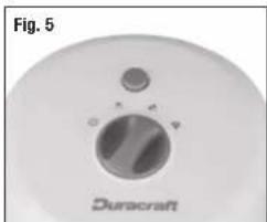
• To operate, press the appropriate speed control option: High (♣), Medium (♣), or Low (♣) (Fig. 5).
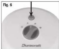
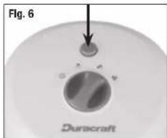
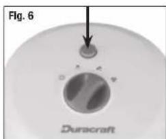
- To activate or disengage the fan oscillation, press the oscillation button (Q) (Fig. 6).
• To turn the fan OFF (⏻) press the Off button once.
natural_image
Close-up of a Dunacraft air purifier fan with control knob (no text or symbols on the fan itself)
HYF013, HYF023 SERIES ASSEMBLY INSTRUCTIONS
NOTE: Remove all contents from the box being careful not to discard the manual and hardware needed for assembly. A phillips head screw driver (8) is required for assembly and is not included with the fan purchase.
A. Pedestal Assembly
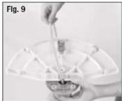
- Place the power cord through the center of the front and rear pedestal assemblies with the screw hole openings facing towards the fan.
- Align the front and rear pedestal assembly and firmly snap together (Fig. 7).
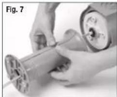
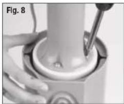
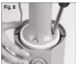
B. Securing the Tower Fan to the Pedestal
• Gently turn fan upside down.
- Line up the 3 screw holes on the pedestal with the 3 screw holes on the bottom of the fan housing. Use the 3 (M5 x 12) screws included in the box and a phillipsheadscrewdriver (⊗) to secure the pedestal to the fan housing (Fig. 8).
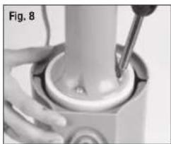
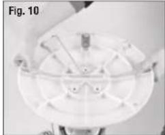
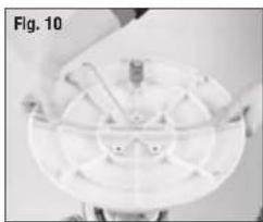
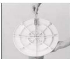
C. Base Assembly
- With the fan in the upside down position, pass the power cord through the recessed slot located in the center of the rear base assembly (Fig. 9).
- Align the rear and front base assembly and firmly snap together by pushing the 4 round extrusion into the adjacent circles of the connecting pieces (Fig. 10).
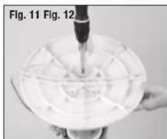
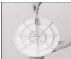
D. Securing the Tower Fan to the Base
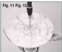
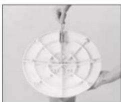
- Align the 3 screw holes in the bottom of the pedestal with the 3 screw holes located on the base. Using the 3 (M5 x 12) screws and phillips head screw driver (③), secure the base into the bottom portion of the fan housing (Fig. 11).
- Place the power cord through the cut out on the bottom of the base. Gently pull any slack out of the power cord and place the cord securely in the power cord holding bracket (Fig. 12).
- Place the fan right side up.
Your fan is now ready for use.
natural_image
Person holding a small object with a tool, viewed from above (no visible text or symbols)
natural_image
Close-up of hands operating a mechanical device with a coiled spring (no visible text or symbols)
natural_image
Close-up of hands using a tool to press or install a mechanical component, no visible text or symbols

natural_image
Top-down view of a white circular mechanical component with radial slots and central hub (no visible text or symbols)
natural_image
Close-up of a hand holding a white circular object with a pipette, labeled Fig. 11 and Fig. 12 (no text or symbols on the object itself)
natural_image
Hand holding a white circular object with radial lines, possibly a dart or target (no visible text or symbols)
HYF013 SERIES OPERATION INSTRUCTIONS
- Place the fan on a level and dry surface.
- Plug the power cord into a polarized 120 Volt AC wall outlet.
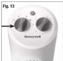
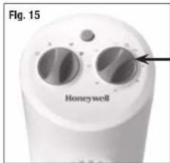
- To operate, turn knob and select appropriate fan speed: High (Medium), Low ( ) (Fig. 13).
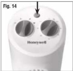
- To activate or disengage the fan oscillation, press the oscillation button. (Q) (Fig. 14).
- Operate the automatic shut-off timer feature by turning the timer knob to the desired setting of 10 to 120 minutes (Fig. 15).
- To turn on the fan after automatic shut-off, turn the knob counterclockwise to the ON position.
• To turn the fan Off, turn knob to the Off position. (⏻)
HYF023 SERIES OPERATION INSTRUCTIONS
- Place the fan on a level and dry surface.
- Plug the power cord into a polarized 120 Volt AC wall outlet.
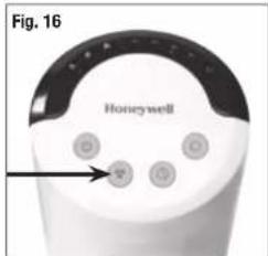
- To turn the fan on, press the Power button (☐) located on the left side of the control panel.
- To select fan speed, press Speed Control button (♣) until the desired speed is selected:
High (♣), Medium (♣ or Low ( ) (Fig. 16).
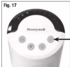
- To activate or disengage the fan oscillation, press the oscillation button (☐). Press the Oscillation button again to turn the Oscillation feature off (Fig. 17).
HYF023 SERIES OPERATION INSTRUCTIONS (CONTINUED)
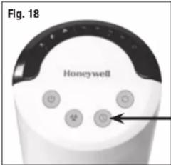
- Activate the Timer feature by pressing the Timer button (☐) (Fig. 18).
Choose from 1, 2, 4 and 8 hour settings by performing the following functions:
• 1 hour: Press the Timer button once.
• 2 hour: Press the Timer button twice.
- 4 hour: Press the Timer button a third time.
- 8 hour: Press the Timer button a fourth time.
Press the Timer button a fifth time to turn the Timer feature off.
- To turn the fan off after use, press the Power button (Once.
USER SERVICING INSTRUCTIONS
CLEANING AND STORAGE
- Unplug the fan before cleaning.
- Use only a soft, damp cloth to gently wipe the outside surface of the fan.
- DO NOT immerse the fan in water and never allow water to drip into the motor housing.
- DO NOT use gasoline, paint thinner or other chemicals to clean the fan.
- Gently wipe the grilles with a cloth. To clean between the grilles we recommend using a pipe cleaner, flexible dustwand, vacuum cleaner or compressed air to gently remove dust. DO NOT IMMERSE THE FAN IN WATER AND NEVER ALLOW WATER TO DRIP INTO THE MOTOR HOUSING. DO NOT USE GASOLINE, PAINT THINNER, OR OTHER CHEMICALS TO CLEAN THE FAN.
- For storage, clean the fan carefully as instructed. Store the fan in the original packaging or cover the product to protect it from dust. Store the fan in a cool, dry place.
CONSUMER RELATIONS
Mail questions or comments to:
Kaz USA, Inc.
Consumer Relations Dept.
250 Turnpike Road
Southborough, MA 01772
Call us toll-free at: 1-800-477-0457
E-mail: consumerrelations@kaz.com
Or visit our website at:
www.honeywellpluggedin.com/fans
Please be sure to specify a model number.
NOTE: IF YOU EXPERIENCE A PROBLEM, PLEASE CONTACT CONSUMER RELATIONS FIRST OR SEE YOUR WARRANTY. DO NOT RETURN TO THE ORIGINAL PLACE OF PURCHASE. DO NOT ATTEMPT TO OPEN THE MOTOR HOUSING YOURSELF, DOING SO MAY VOID YOUR WARRANTY AND CAUSE DAMAGE.
THIS DEVICE (HYF023 SERIES ONLY) COMPLIES WITH PART 15 OF THE FCC RULES
NOTE: This equipment has been tested and found to comply with the limits for a Class B digital device, pursuant to Part 15 of the FCC Rules. These limits are designed to provide reasonable protection against harmful interference in a residential installation. This equipment generates, uses, and can radiate radio frequency energy and, if not installed and used in accordance with the instructions, may cause harmful interference to radio communications. However, there is no guarantee that interference will not occur in a particular installation. If this equipment does cause harmful interference to radio or television reception, which can be determined by turning the equipment off and on, the user is encouraged to try to correct the interference by one or more of the following measures:
- Reorient or relocate the receiving antenna.
- Increase the separation between the equipment and receiver.
- Connect the equipment into an outlet on a circuit different from that to which the receiver is connected.
- Consult the dealer or an experienced radio TV technician for help.
Please note that changes or modifications of this product is not expressly approved by the party responsible for compliance could void the user's authority to operate the equipment.
1 YEAR LIMITED WARRANTY
You should first read all instructions before attempting to use this product.
A. This 1 year limited warranty applies to repair or replacement of product found to be defective in material or workmanship. This warranty does not apply to damage resulting from commercial, abusive, unreasonable use or supplemental damage. Defects that are the result of normal wear and tear will not be considered manufacturing defects under this warranty.
KAZ USA, INC. IS NOT LIABLE FOR INCIDENTAL OR CONSEQUENTIAL DAMAGES OF ANY NATURE. ANY IMPLIED WARRANTY OF MERCHANTABILITY OR FITNESS FOR A PARTICULAR PURPOSE ON THIS PRODUCT IS LIMITED IN DURATION TO THE DURATION OF THIS WARRANTY. Some jurisdictions do not allow the exclusion or limitation of incidental or consequential damages or limitations on how long an implied warranty lasts, so the above limitations or exclusions may not apply to you. This warranty gives you specific legal rights, and you also may have other rights which vary from jurisdiction to jurisdiction. This warranty applies only to the original purchaser of this product from the original date of purchase.
B. At its option, Kaz USA, Inc. will repair or replace this product if it is found to be defective in material or workmanship.
C. This warranty does not cover damage resulting from any unauthorized attempts to repair or from any use not in accordance with the instruction manual.
D. Return defective product to Kaz USA, Inc. with a brief description of the problem. Include proof of purchase and a \10 US/\15.50 CAN check or money order for handling, return packing and shipping charges. Please include your name, address and a daytime phone number.
You must prepay shipping charges.
We suggest having tracking or delivery confirmation. Send to:
In U.S.:
Attn: Returns Department
1 Helen Of Troy Plaza
El Paso, TX 79912
USA
In Canada:
Kaz Canada, Inc.
Attn: Returns Department
510 Bronte Street South
Milton, ON L9T 2X6
Canada
Please go to
www.honeywellpluggedin.com/register and register your product under the Customer Care Center and receive product information updates and new promotional offers.
Guide d'utilisation
Honeywell
natural_image
Four white and black electronic tower holders with ventilation grilles, arranged side by side (no text or symbols visible)
⚠️ IMPORTANTES INSTRUCTIONS DE SÉCURITÉ
LIRE ET CONSERVER CES INSTRUCTIONS DE SÉCURITÉ AVANT D'UTILISER LE VENTILATEUR
natural_image
Close-up of a hand holding a mechanical component, possibly a valve or pump, with no visible text or symbols.
natural_image
Close-up of hands operating a mechanical device with a circular component (no visible text or symbols)
natural_image
Close-up of hands holding a circular mechanical component with radial slots and a central hub (no visible text or symbols)

natural_image
Close-up of hands holding a circular mechanical component with internal wiring (no visible text or symbols)
INSTRUCTIONS DE FONCTIONNEMENT POUR LA SÉRIE DYF012
natural_image
Close-up of a circular device with a dial and control knob, labeled 'Duracraft' (no additional text or symbols visible)
DIRECTIVES D'ASSEMBLAGE POUR LA SÉRIE HYF023
natural_image
Close-up of hands operating a mechanical device with a spool, labeled 'Fig. 7' (no visible text or symbols on the device itself)
natural_image
Close-up of a hand using a screwdriver to press or install a cylindrical component (no visible text or symbols)

natural_image
Person holding a small object with a tool, viewed from above (no visible text or symbols)
natural_image
Top-down view of a circular mechanical component with internal components and mounting holes (no visible text or symbols)
natural_image
Close-up of a hand holding a transparent container with a pipette inserted, no visible text or symbols
natural_image
Hand holding a dartboard with a target-like design (no visible text or symbols)
INSTRUCTIONS DE FONCTIONNEMENT POUR LA SÉRIE HYF013
Consumer Relations Dept.
250 Turnpike Road
Southborough, MA 01772
natural_image
Four different types of outdoor air conditioners or fans, shown in white and black, arranged side by side (no text or symbols visible)
natural_image
Close-up of hands cleaning a small container with a lid (no visible text or symbols)
natural_image
Close-up of hands holding a circular mechanical component with internal grid pattern (no visible text or symbols)
natural_image
Close-up of hands operating a mechanical device with a tool inserted (no visible text or symbols)
natural_image
Close-up of hands assembling a circular mechanical component with internal channels (no visible text or symbols)
natural_image
Close-up of a Dunacraft air purifier fan with control knob (no text or symbols on the fan itself)
natural_image
Close-up of hands operating a mechanical device with a spool, labeled as Fig. 7 (no visible text or symbols on the device itself)
natural_image
Close-up of hands using a screwdriver to press a mechanical component (no visible text or symbols)
natural_image
Close-up of a mechanical component with a circular housing and radial slots (no visible text or symbols)
natural_image
Hand holding a white circular object with radial lines, possibly a dart or target (no text or symbols visible)
Consumer Relations Dept.
250 Tumpike Road
Southborough, MA 01772
Kaz Symbol for MOHS compliance


For Responsible recycling, please visit:
Para reciclar responsablemente, por favor visite:
1·800·RECYCLING.com®
www.1800recycling.com
Model: DYF012 HYF013 HYF023
Artwork Part #: 31IMDYHY190
Die Line Part #: N/A
Oracle Desc.: OM, DYF012W SERIES, HYF013W SERIES, HYF023W SERIES, ENGLISH/FRENCH/SPANISH, 2015
Subject: Owners Manual
Region: US
Flat Size: IN: W 11 x H 8
MM: W x H
Folded Size: W 5.5 x H 8
Scale: 1/1
Material: 70# Matte text
Page count: 24
Revision: 1
Date: 01SEP15
Release Date: 09SEP15
Rerelease Date:
Colors:
Dielines (Do not print)
Molded In
Quality Requirement of Artwork and Quality Clarification Process of Artwork Printing: Meet Eng-QS-06&02
Kaz USA, Inc.
Creative Services, 250 Turnpike Road
Southborough, 01772 MA, USA
+1 508 490 7000