
HW-305 Twin Window - Fan HONEYWELL - Free user manual and instructions
Find the device manual for free HW-305 Twin Window HONEYWELL in PDF.


| Product Type | Twin Window Fan |
| Brand | Honeywell |
| Model | HW-305 Twin Window |
| Dimensions (L x H x D) | 25 x 25 x 15 cm |
| Net Weight | 2,8 kg |
| Power Supply | 220-240 V ~ 50 Hz |
| Power Consumption | 30 W |
| Number of Speeds | 2 (low, high) |
| Airflow Reversal Function | Yes (summer/winter) |
| Built-in Thermostat | Yes, adjustable |
| Control | Manual via buttons |
| Power Cord Length | 1,8 m |
| Main Material | ABS Plastic |
| Protective Grille | Yes, removable for cleaning |
| Care and Cleaning | Clean with a damp cloth, do not immerse |
| Safety | Auto shut-off in case of overheating |
| Spare Parts Available | Filter, power cord, mounting feet |
| Repairability | Manufacturer after-sales service, parts available |
| Warranty | 2 years |
Frequently Asked Questions - HW-305 Twin Window HONEYWELL
User questions about HW-305 Twin Window HONEYWELL
0 question about this device. Answer the ones you know or ask your own.
Ask a new question about this device
Download the instructions for your Fan in PDF format for free! Find your manual HW-305 Twin Window - HONEYWELL and take your electronic device back in hand. On this page are published all the documents necessary for the use of your device. HW-305 Twin Window by HONEYWELL.
USER MANUAL HW-305 Twin Window HONEYWELL
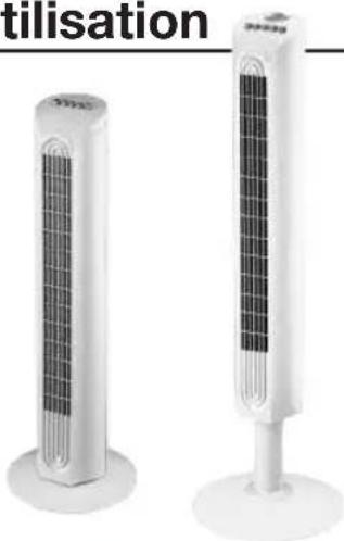
TOWER FAN
Model DY-012 Series
Model HY-013 Series
IMPORTANT SAFETY INSTRUCTIONS
READ AND SAVE THESE SAFETY INSTRUCTIONS BEFORE USING THIS FAN
When using electrical appliances, basic precautions should always be followed to reduce the risk of fire, electric shock, and injury to persons, including the following:
- Use this fan only as described in this manual. Other use not recommended as it may cause fire, electric shock or injury to persons.
- This product is intended for household use ONLY and not for commercial, industrial or outdoor use.
- To protect against electric shock, do not place fan in window, immerse unit, plug or cord in water or spray with liquids.
- This appliance has a polarized plug (one blade is wider than the other). To reduce the risk of shock, this plug is intended to fit only one way in a polarized outlet. If the plug does not fitfully in the outlet, reverse the plug. If it still does not fit, contact a qualified electrician. Do not attempt to defeat this safety feature.
- Close supervision is necessary when any appliance is used by or near children.
- T urn the fan OFF and unplug the fan from
the outlet when not in use, when moving the fan from one location to another and before cleaning.
- To disconnect the fan, first turn the unit OFF, grip the plug and pull it from the wall outlet. Never pull the plug by the cord.
8 Do not operate the fan in the presence of explosive and/or flammable fumes. - Do not place the fan or any parts near an open flame, cooking or other heating appliance.
- Do not operate the fan with a damaged cord or plug or if the product malfunctions, is dropped or damaged in any manner (see warranty).
- Avoid contact with moving fan parts.
- The use of attachments not recommended by the manufacturer may be hazardous.
- Place the fan on a dry level surface.
- Do not hang or mount fan on a wall or ceiling.
- Do not operate if the fan housing is damaged.
- A loose fit between the AC outlet (receptacle) and plug may cause over heating and a distortion of the plug. Contact a qualified electrician to replace loose or worn outlet.
WARNING: To Reduce The Risk of Fire or Electric Shock, Do Not Use This Fan With Any Solid-State Speed Control Device.
DY-012 SERIES ASSEMBLY INSTRUCTIONS
NOTE: Remove all contents from the box being careful not to discard the manual and hardware needed for assembly. A phillips head screw driver (E) is required for assembly and is not included with the fan purchase.
A. Base Assembly
• Gently turn the fan upside down.
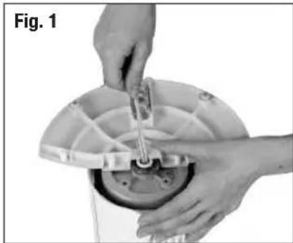
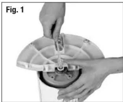
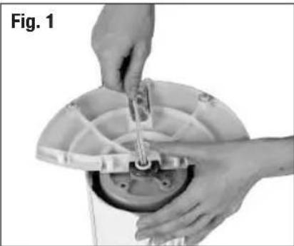
- Place the power cord through the recessed channel located in the center of the rear base assembly (Fig 1).
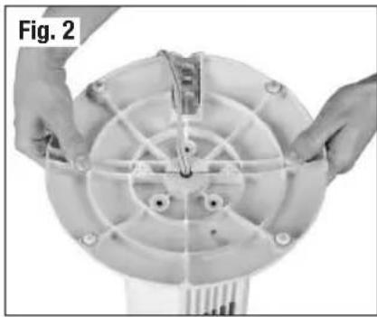
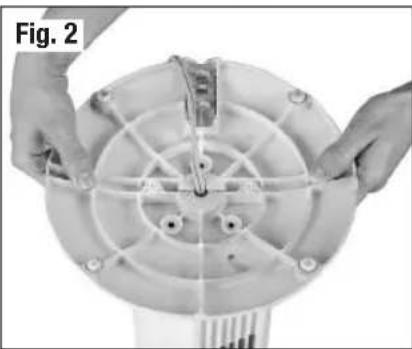
- Align the rear and front base assembly and firmly snap together by pushing the 4 round extrusion into the adjacent circles of the connecting pieces (Fig 2).
B. Securing the Tower Fan to the Base
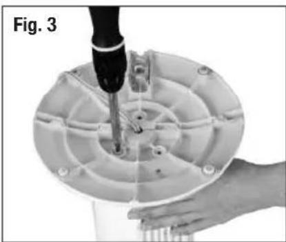
- Using the 3 (M5 x 12) screws and phillips head screw driver () secure the base into the bottom portion of the fan housing by aligning the 3 screw holes on the base with the 3 screw holes on the bottom of the fan housing (Fig 3).
• Gently pull any slack out of the power cord and place the cord
securely in the power cord holding bracket (Fig. 4).
- Place the fan right side up. Your fan is now ready for use.


DY-012 SERIES OPERATION INSTRUCTIONS
- Be sure your fan is in the OFF position by pressing the off button. (💡)
- Place the fan on a level and dry surface.
- Plug the power cord into a polarized 120 Volt AC wall outlet.
- To operate, press the appropriate speed control option: High (♣Medium ( ), ♦Low ( ) (Fig.5).

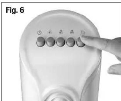
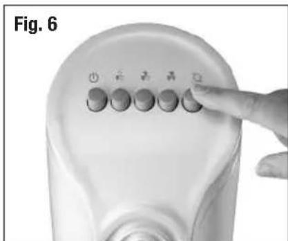
- To activate or disengage the fan oscillation, press the oscillation button ( Fig 6).
- To turn the fan OFF (Press the Off button once.
HY-013 SERIES ASSEMBLY INSTRUCTIONS
NOTE: Remove all contents from the box being careful not to discard the manual and hardware needed for assembly. A phillips head screw driver (☒) is required for assembly and is not included with the fan purchase.
A. Pedestal Assembly
- Place the power cord through the center of the front and rear pedestal assemblies with the screw hole openings facing towards the fan.
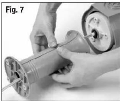
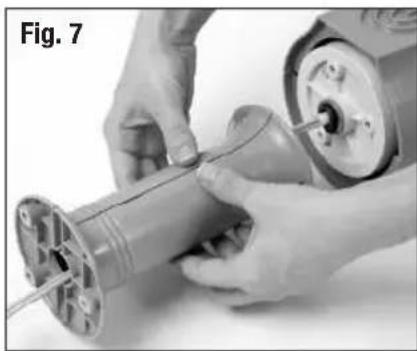
- Align the front and rear pedestal assembly and firmly snap together (Fig 7).
B. Securing the Tower Fan to the Pedestal
• Gently turn fan upside down.
- Line up the 3 screw holes on the pedestal with the 3 screw holes on the bottom of the fan housing. Use the 3 (M5 x 12) screws included in the box and a phillips head screw driver (✗) to secure the pedestal to the fan housing (Fig. 8).
C. Base Assembly
- With the fan in the upside down position, pass the power cord through the recessed slot located in the center of the rear base assembly (Fig 9).
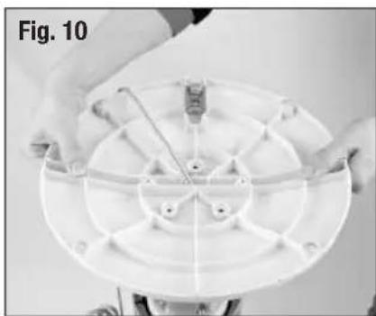
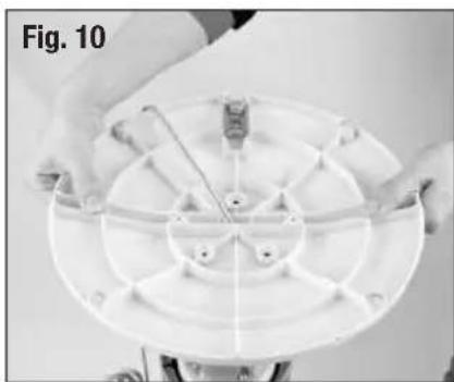
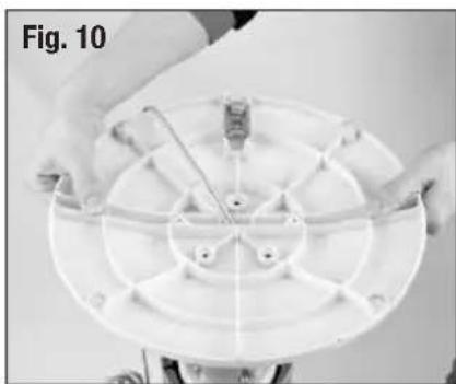
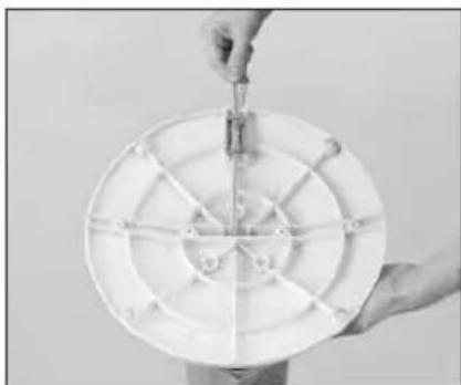
- Align the rear and front base assembly and firmly snap together by pushing the 4 round extrusion into the adjacent circles of the connecting pieces (Fig 10).
D. Securing the Tower Fan to the Base
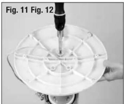
- Align the 3 screw holes in the bottom of the pedestal with the 3 screw holes located on the base. Using the 3 (M5 x 12) screws and phillips head screw driver ( secure the base into the bottom portion of the fan housing (Fig 11).
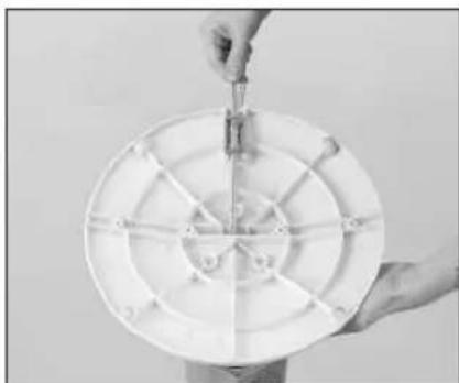
- Place the power cord through the cut out on the bottom of the base. Gently pull any slack out of the power cord and place the cord securely in the power cord holding bracket (Fig. 12).


- Place the fan right side up. Your fan is now ready for use.
HY-013 SERIES OPERATION INSTRUCTIONS
- Be sure your fan is in the OFF position by pressing the off button. (☐)
- Place the fan on a level and dry surface.
- Plug the power cord into a polarized 120 Volt AC wall outlet.
- To operate, press the appropriate speed control option: High (Medium (or Low ( ) (Fig. 13).
- To activate or disengage the fan oscillation, press the oscillation button. (Fig 14).
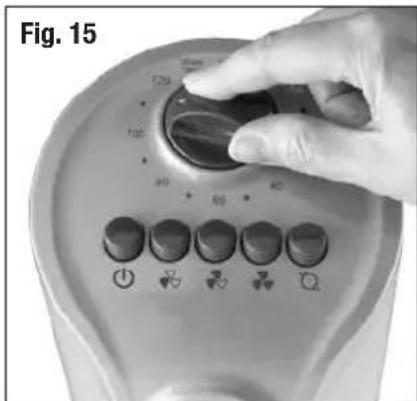
- Operate the automatic shut-off timer feature by turning the timer knob to the desired setting of 10 to 120 minutes (Fig 15).
• To turn on the fan after automatic shut-off, turn the knob counterclockwise to the ON position.
• To turn the fan off press the Off button once. (💡)
Fig. 13

Fig. 14

CLEANING AND STORAGE
- Unplug the fan before cleaning.
- Use only a soft, damp cloth to gently wipe the outside surface of the fan.
- DO NOT immerse the fan in water and never allow water to drip into the motor housing.
- DO NOT use gasoline, paint thinner or other chemicals to clean the fan.
- Gently wipe the grilles with a cloth. To clean between the grilles we recommend using a pipe cleaner, flexible dustwand, vacuum cleaner or compressed air to gently remove dust. DO NOT IMMERSE THE FAN IN WATER AND NEVER ALLOW WATER TO DRIP INTO THE MOTOR HOUSING. DO NOT USE GASOLINE, PAINT THINNER, OR OTHER CHEMICALS TO CLEAN THE FAN.
- For storage, clean the fan carefully as instructed. Store the fan in the original packaging or cover the product to protect it from dust. Store the fan in a cool, dry place.
CONSUMER RELATIONS
Mail questions or comments to:
Kaz, Incorporated
Consumer Relations Dept.
250 Turnpike Road
Southborough, MA 01772
Call us toll-free at: 1-800-477-0457
E-mail: consumerrelations@kaz.com
Or visit our website at: www.kaz.com
Please be sure to specify a model number.
NOTE: IF YOU EXPERIENCE A PROBLEM, PLEASE CONTACT CONSUMER RELATIONS FIRST OR SEE YOUR WARRANTY. DO NOT RETURN TO THE ORIGINAL PLACE OF PURCHASE. DO NOT ATTEMPT TO OPEN THE MOTOR HOUSING YOURSELF, DOING SO MAY VOID YOUR WARRANTY AND CAUSE DAMAGE.
1 YEAR LIMITED WARRANTY
You should first read all instructions before attempting to use this product.
A. This 1 year limited warranty applies to repair or replacement of product found to be defective in material or workmanship. This warranty does not apply to damage resulting from commercial, abusive, unreasonable use or supplemental damage. Defects that are the result of normal wear and tear will not be considered manufacturing defects under this warranty.
KAZ IS NOT LIABLE FOR INCIDENTAL OR CONSEQUENTIAL DAMAGES OF ANY NATURE. ANY IMPLIED WARRANTY OF MERCHANTABILITY OR FITNESS FOR A PARTICULAR PURPOSE ON THIS PRODUCT IS LIMITED IN DURATION TO THE DURATION OF THIS WARRANTY. Some jurisdictions do not allow the exclusion or limitation of incidental or consequential damages or limitations on how long an implied warranty lasts, so the above limitations or exclusions may not apply to you. This warranty gives you specific legal rights, and you also may have other rights which vary from jurisdiction to jurisdiction. This warranty applies only to the original purchaser of this product from the original date of purchase.
B. At its option, Kaz will repair or replace this product if it is found to be defective in material or workmanship.
C. This warranty does not cover damage resulting from any unauthorized attempts to repair or from any use not in accordance with the instruction manual.
D. Return defective product to Kaz, Incorporated with a brief description of the problem. Include proof of purchase and a \10 US/\15.50 CAN check or money order for handling, return packing and shipping charges. Please include your name, address and a daytime phone number.
You must prepay shipping charges. We suggest having tracking or delivery confirmation. Send to:
In U.S.:
Kaz, Incorporated Attn: Returns Department 4755 Southpoint Drive Memphis, TN 38118 USA
In Canada:
Kaz Canada Inc. Attn: Returns Department 510 Bronte Street South Milton, ON L9T 2X6 Canada
Please go to www.kaz.com and register your product under the Customer Care Center and receive product information updates and new promotional offers.
Guide d'utilisation
IMPORTANTES INSTRUCTIONS DE SÉCURITÉ
LIRE ET CONSERVER CES INSTRUCTIONS DE SÉCURITÉ AVANT D'UTILISER LE VENTILATEUR

INSTRUCTIONS DE FONCTIONNEMENT POUR LA SÉRIE DY-012


INSTRUCTIONS DE FONCTIONNEMENT POUR LA SÉRIE HY-013
NETTOYAGE ET ENTREPOSAGE
Consumer Relations Dept.
250 Turnpike Road
Southborough, MA 01772
Kaz, Incorporated Attn: Returns Department 4755 Southpoint Drive Memphis, TN 38118 USA
Au Canada:
Kaz Canada Inc. Attn: Returns Department 510 Bronte Street South Milton, ON L9T 2X6 CANADA


INSTRUCCIONES DE ENSAMBLAJE DE LA SERIE HY-013



LIMPIEZA Y ALMACENAMIENTO
Consumer Relations Dept.
250 Turnpike Road
Southborough, MA 01772
Attn: Returns Department
4755 Southpoint Drive
Memphis, TN 38118
USA
En Canadá:
Kaz Canada Inc.
Attn: Returns Department
510 Bronte Street South
Milton, ON L9T 2X6
CANADA
- TOWER FAN
- IMPORTANT SAFETY INSTRUCTIONS
- READ AND SAVE THESE SAFETY INSTRUCTIONS BEFORE USING THIS FAN
- DY-012 SERIES ASSEMBLY INSTRUCTIONS
- BASE ASSEMBLY
- SECURING THE TOWER FAN TO THE BASE
- DY-012 SERIES OPERATION INSTRUCTIONS
- HY-013 SERIES ASSEMBLY INSTRUCTIONS
- PEDESTAL ASSEMBLY
- SECURING THE TOWER FAN TO THE PEDESTAL
- HY-013 SERIES OPERATION INSTRUCTIONS
- CLEANING AND STORAGE
- CONSUMER RELATIONS
- 1 YEAR LIMITED WARRANTY
- YOU SHOULD FIRST READ ALL INSTRUCTIONS BEFORE ATTEMPTING TO USE THIS PRODUCT
- IN U.S
- IN CANADA
- GUIDE D'UTILISATION
- IMPORTANTES INSTRUCTIONS DE SÉCURITÉ
- LIRE ET CONSERVER CES INSTRUCTIONS DE SÉCURITÉ AVANT D'UTILISER LE VENTILATEUR
- INSTRUCTIONS DE FONCTIONNEMENT POUR LA SÉRIE DY-012
- INSTRUCTIONS DE FONCTIONNEMENT POUR LA SÉRIE HY-013
- NETTOYAGE ET ENTREPOSAGE
- AU CANADA
- INSTRUCCIONES DE ENSAMBLAJE DE LA SERIE HY-013
- LIMPIEZA Y ALMACENAMIENTO
- EN CANADÁ
Brand : HONEYWELL
Model : HW-305 Twin Window
Category : Fan